Difference between revisions of "S18: Smart Rock Paper Scissors"
Proj user3 (talk | contribs) (→Schedule) |
Proj user3 (talk | contribs) (→Schedule) |
||
| Line 124: | Line 124: | ||
| 05/22 | | 05/22 | ||
| Finish debugging project for demo. | | Finish debugging project for demo. | ||
| − | | Completed | + | | Completed? Problems Encountered? |
|- | |- | ||
|} | |} | ||
Revision as of 00:04, 23 May 2018
Contents
Smart Rock Paper Scissors
Hand gesture controlled rock paper scissors game.
Abstract
This project recreates the classic Rock,Paper, Scissors game using a LED Matrix to display and keep track of scoring, and wireless gloves to record the user input. The LED Matrix helps users to know what round they are on, what the score is, as well as provide prompts of when to give the Rock, Paper or Scissors signal. The Smart aspect of the system also allows users to play against a computer player. The wireless gloves utilize Bluetooth modules and flex sensors to detect the player input and feed that input into the game logic and game controller.
Objectives & Introduction
- Create LED display to guide players through the game
- Create wireless gloves to allow players to give input
- Create feedback to the gloves to enhance the game experience
- Make the game platform modular, so other games could be easily built with the system
Team Members & Responsibilities
- Josh Skow
- System Integration
- PCB
- Kaustubh Jawalekar
- Bluetooth
- Glove, Sensors
- Kevin Gadek
- LED Display
- Akinfemi Aluko
- Bluetooth
- Glove, Sensors
- Sarvpreet Singh
- LED Display
Schedule
Show a simple table or figures that show your scheduled as planned before you started working on the project. Then in another table column, write down the actual schedule so that readers can see the planned vs. actual goals. The point of the schedule is for readers to assess how to pace themselves if they are doing a similar project.
| Week# | Date | Task | Actual |
|---|---|---|---|
| 1 | 03/20 | Submit Project Proposal | Completed.
Had to modify project proposal from original submission. |
| 2 | 03/27 | Determine project architecture | Completed. |
| 3 | 04/03 | Order Parts | Completed. |
| 4 | 04/10 | Begin work on Display, Bluetooth
Begin work on PCB. Begin testing glove sensors. |
Completed. |
| 5 | 04/17 | Write multiple lines on Display Successfully
Set Bluetooth device to master mode Read valid data from flex sensor |
Completed.
Had to purchase a Bluetooth module that supports master mode. |
| 6 | 04/24 | Draw full image on Display.
Complete Bluetooth logic. Begin working on game logic and game state machine. Begin assembling glove and sensors to mount on wrist. Finish PCB, and submit PCB layout to fab. |
Game logic completed. Bluetooth logic working, and basic gloves put together. |
| 7 | 05/01 | Finalize glove design, and wrist mounting.
Finish Display logic. Finalize game logic. Receive PCB from fab, populate and test PCB. |
Completed.
PCB received. Glove drivers working and glove is physically put together. |
| 8 | 05/08 | Test for edge cases with game logic.
Fine tune display images for game. Add game features if time permits. Re-work PCB as needed based on testing. |
Completed |
| 9 | 05/15 | Complete final project documentation.
Prepare project for demo. |
Completed? Problems Encountered? |
| 10 | 05/22 | Finish debugging project for demo. | Completed? Problems Encountered? |
Parts List & Cost
| Part Name | Description | Link | Quantity | Cost |
|---|---|---|---|---|
| 32x32 RGB LED Matrix | 32x32 Matrix to display game | Link | 1 | $44.95 |
| Bluetooth HC-05 Module | Bluetooth module with master mode capability | Link | 2 | $29.90 |
| XBee Bluetooth HC-06 Module | Gikfun HC-06 Bluetooth Bee V2.0 Slave Module | Link | 2 | $23.96 |
| SJOne Boards | Microcontrollers | N/A | 4 | $320 |
| Flex Sensors | Flex sensors to measure finger flex | Link | 4 | $26 |
| Parallax 28821 Vibration motors | Feedback motors | Link | 2 | $11 |
| Gloves | Gloves to record gestures | Link | 2 | $20 |
| PCB | PCB to route power | Link | 3 | $140 |
Design & Implementation
The design section can go over your hardware and software design. Organize this section using sub-sections that go over your design and implementation.
Hardware Design
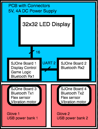
Smart Rock Paper Scissors used a 32x32 LED Display, four Bluetooth modules, and four SJOne boards as the primary hardware devices in the system. Two SJOne boards were used as Bluetooth receivers, and two SJOne boards were used as Bluetooth transmitters. One Bluetooth receiver board was also responsible for driving the LED Display and handling the Rock, Paper, Scissors logic.
A PCB was created in order to route power from a 5V, 4A AC/DC power supply to the LED display, and both Bluetooth receiver SJOne boards. The SJOne boards attached to the glove controllers each use USB power banks to power the board.
Figure 1: Block diagram of the Smart Rock, Paper, Scissors hardware components.
Bluetooth Gloves
|
Flex Sensors Flex sensors are used to detect the hand gesture of the user. Two flex sensors are used on fingers 2 and 4, if paper both are not bent, if scissors one is bent and if rock both are bent.
|
[[File:|100px|left|frame|Glove Picture]] |
LED Matrix
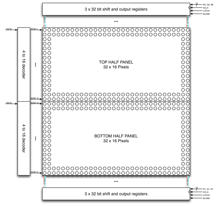
The LED Matrix is composed of 1024 RGB LEDs arranged in a 32x32 matrix. Each RGB LED contains separate red, green, and blue LED chips within a single package. The display is split horizontally into two equal halves with 16 rows and 32 columns each. The display's columns are driven by one set of drivers and its rows by another set. In order for a particular LED to be lit, both its column and row driver have to be on. To manipulate the color of a specific LED, the red, green, and blue chips in the column driver are controlled separately. The column driver devolves into 3 32-bit shift registers as well as 3 32-bit parallel data registers. On each rising edge of the shift clock, whatever data is present at the 6 data inputs gets shifted in. Once the shift registers are filled, the latch signal is asserted to latch these register contents into the parallel data output register. The overall schematic for the LED Matrix is provided below.
Figure ?: LED Matrix Hardware Configuration (Source: http://bikerglen.com/projects/lighting/led-panel-1up/)
Printed Circuit Board (PCB) Design
The PCB is used to distribute power between the SJOnes an the LED display from the DC Power Jack. The PCB also routes the LED control and data signals to the SJOne.
Hardware Interface
In this section, you can describe how your hardware communicates, such as which BUSes used. You can discuss your driver implementation here, such that the Software Design section is isolated to talk about high level workings rather than inner working of your project.
Bluetooth Gloves
The hardware interface to the Flex sensors uses ADC for input and ground to complete connection. Vibration motor uses GPIO. Bluetooth HC-05 uses UART connection to the SJOne board.
| SJ One Board Pin | Description |
|---|---|
| P0.0 | Vibration motor Vcc |
| P0.1 | Flex Sensor1 Vcc |
| P2.7 | Flex Sensor2 Vcc |
| P0.26 | Flex Sensor1 ADCin |
| P1.31 | Flex Sensor2 ADCin |
| P RxD2 | Bluetooth HC05 Tx |
| P TxD2 | Bluetooth HC05 Rx |
| PTxD2 | Bluetooth HC05 Vcc |
| P GND | Common to Flex sensors |
| P GND | Bluetooth HC05 GND |
| P GND | Vibration motor GND |
LED Matrix
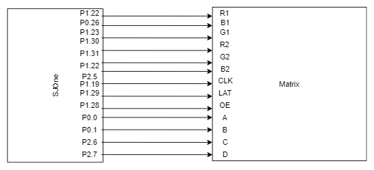
The hardware interface to the LED Matrix uses GPIO for all data and control lines. A GPIO clock is toggled to shift in data sitting at the Matrix's 6 data ports.
| SJ One Board Pin | Name | Description |
|---|---|---|
| P0.0 | addrA | Address Input A |
| P0.1 | addrB | Address Input B |
| P2.6 | addrC | Address Input C |
| P2.7 | addrD | Address Input D |
| P1.29 | Latch | Shift in row data/Active High |
| P1.28 | Output Enable | Turn on selected rows/Active Low |
| P1.19 | Clock | Shift clock |
| P1.22 | R1 | Top half red data |
| P0.26 | G1 | Top half green data |
| P1.23 | B1 | Top half blue data |
| P1.30 | R2 | Bottom half red data |
| P1.31 | G2 | Bottom half green data |
| P2.5 | B2 | Bottom half blue data |
Figure ?: Matrix Hardware Interface Block Diagram
PCB Interface
The PCB has a 2x8 header to connect to the LED display, a 2x10 header to connect to the SJOne, a 2 pin header to connect to the UART of SJOne Board 1, and a 3 pin header to connect to the Ground and UART of SJOne Board 2.
Software Design
Show your software design. For example, if you are designing an MP3 Player, show the tasks that you are using, and what they are doing at a high level. Do not show the details of the code. For example, do not show exact code, but you may show psuedocode and fragments of code. Keep in mind that you are showing DESIGN of your software, not the inner workings of it.
Game Control Logic
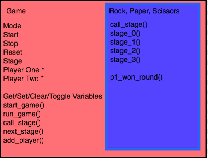
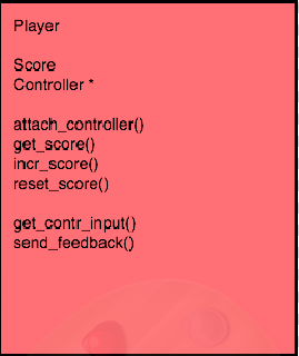
Smart Rock Paper Scissors was designed using classes to support a generic game flow. Rock, Paper, Scissors is a type of game, and each game has up to two players and one display. Each player has a score and a controller. The display and controller classes use initialization methods in order to create tasks to handle the display and controller drivers.
The game parent class creates a task that handles the flow of each game in stages. A game is started by calling "start_game" on an instance of the game you wish to start. Start game will create a task for the game logic, and then launch the task scheduler.
Figure X: Game and Rock, Paper, Scissors Classes
The game task operates on a private "stage" variable, where each stage is an abstraction of levels for different types of games. The game task will continually call the virtual function get_stage(). get_stage() must be defined by the subclass game, in this case Rock, Paper, Scissors. The Rock, Paper, Scissors get_stage() will determine which stage to call based on the current stage value, and will handle switching between stages as makes sense in the flow of the game. The game task will run forever unless the developer implements logic for the "stop" variable. The game class maintains this "stop" variable in case the developer wants to quit the current game type.
Figure X: Player Class
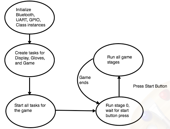
The game class also has "start", "mode" and "reset" variables that help to control the flow of the game. For Rock, Paper, Scissors, the start variable corresponds to an external start switch. When the start switch is pressed, the game "start" is set to high and the Rock, Paper, Scissors will begin the rounds of the game.
Figure X: Overall Software Flow of Smart Rock, Paper Scissors
Bluetooth Gloves
LED Matrix
An LEDMatrixGPIO class was built for the purposes of providing a common singleton instance to allow our state machine to easily draw images on our LED Matrix. A uint32_t 2-D array object called frameBuffer stored as a private member of this class is used to store the current 'image frame' that should be displayed on the matrix. The 32-bit pixel data for each row and each color is stored within this singular frameBuffer. The class provides API functions that will be used by our state machine such as drawStartScreen(), drawScoreboard(), drawRoundEnd(), drawGameOver(), and updateDisplay() are described in detail below.
updateDisplay()
The core of the LED Matrix API is an updateDisplay function that is called by a Repetitive Interrupt Timer at a rate of 30-50 MHz. This essentially acts as our refresh clock frequency. The updateDisplay code fragment is shown below.
//designed to loop through frameBuffer and shift data for paired rows
void updateDisplay()
{
    //only need to iterate up to 16 because we're doing 2 rows at a time
    for(int i = 0; i < 16; i++)
    {
        setEn(true); //turn off currently displayed row
        setLatch(false); //about to shift in data so make sure that data isn't latched until whole row is shifted in
        selRow(i); //will select i and i+16 rows at same time, this function sets 4 address lines to select correct rows
        //this inner loop will shift MSB of frameBuffer[i] first into corresponding shift register
        for(int j = 31; j >= 0; j--)
        {
            ((frameBuffer[i][0] >> j) & 1) ? r1->setHigh() : r1->setLow(); //shift in r1 data with msb getting shifted in first
            ((frameBuffer[i][1] >> j) & 1) ? g1->setHigh() : g1->setLow(); //g1 data
            ((frameBuffer[i][2] >> j) & 1) ? b1->setHigh() : b1->setLow(); //b1 data

            //bottom half for corresponding row; rows 0/16, 1/17 etc
            ((frameBuffer[i + 16][0] >> j) & 1) ? r2->setHigh() : r2->setLow(); //r2
            ((frameBuffer[i + 16][1] >> j) & 1) ? g2->setHigh() : g2->setLow(); //g2
            ((frameBuffer[i + 16][2] >> j) & 1) ? b2->setHigh() : b2->setLow(); //b2
            clk->setHigh(); clk->setLow();  //shift in all 6 bits at once
        }

        //at this point, all 3 shift registers should be filled with corresponding row data in frameBuffer
        setLatch(true); //latch shift register contents down to parallel output register
        setEn(false); //turn on two rows i and i+16
        delay_us(250); //very small delay to reduce flickering
    }
}
With this updateDisplay running in the background, drawing images simply entails updating frameBuffer with the bit representations of desired images and letting updateDisplay handle the overhead of toggling control signals such as latch and output enable. For each 'image' that we're using, such as words, numbers and graphics, the bitmap representations had to be painstakingly obtained so that information about which pixels are lit could be procured for each row and each color.
drawStartScreen()
drawStartScreen() works by copying a pre-built startScreenImg 2-D array into the common frameBuffer instance. The refresh function running in the background continually calling updateDisplay() will handle the actual overhead of drawing the image. An animation is used within drawStartScreen to switch between a 'START' idle image as well as a 'MODE' image indicating the current mode that the game is set to (1P or 2P). When the appropriate switch is pressed, the state machine clears the screen and calls drawScoreboard().
Put Image here
drawScoreboard(uint8_t roundNum, uint8_t leftScore, uint8_t rightScore)
This function is used to draw the entire pre-round animation as well as re-draw the in-round score. First, it continually updates the frameBuffer to allow an animation of 'Round' from the bottom to the top of the screen. Once there, it displays roundNum and flashes the round before disappearing for the scoreboard. Regardless of 1P or 2P mode, the players are the same with P1 and P2/CPU. This function calls a drawCountdown() that counts down from 3 to synchronize the recorded player gestures. Afterwards, a drawAction(Action left, Action right) call is made to draw the gestures of each player. A new Action enumeration was made with Rock, Paper, and Scissors as possible options.
Put Image here
drawRoundEnd(Player winner)
This function is called after a drawScoreboard call once a winner has been determined. A new Player enumeration was created so the state machine can indicate whether Player1, Player2 or Neither was the winner. This function clears all pixels under the scoreboard and displays a winner animation.
Put Image here
drawGameOver(Player matchWinner)
This function is called when a player reaches the end condition of 3 wins. This function clears the screen and then displays the winner. Slight alterations are made on this screen depending on mode.
Put Image here
Implementation
This section includes implementation, but again, not the details, just the high level. For example, you can list the steps it takes to communicate over a sensor, or the steps needed to write a page of memory onto SPI Flash. You can include sub-sections for each of your component implementation.
Bluetooth Gloves
Steps to acquire data from gloves and send it via Bluetooth to controller
- Initialize ADC for 2 channels
- Initialize UART2
- Read ADC input and write it to UART2
- If the data is read successfully and received feedback from the controller, vibrate the indicator motor
- Repeat this process for every round
LED Matrix
Steps to write to LED Matrix:
- Set output enable HIGH to disable LED output for selected row
- Set latch LOW to block shift register from pushing to parallel data output register
- Shift in 32 bits of data for R1, G1, B1, R2, G2, B2 for rows 0/16
- Set addr lines A, B, C, D to select rows 0/16
- Set latch HIGH to move shift register data into parallel data output register
- Set output enable LOW to display currently selected row
- Repeat this process for the other rows 100 to 200 times per second
Testing & Technical Challenges
//Describe the challenges of your project. What advise would you give yourself or someone else if your project can be started from scratch again? //Make a smooth transition to testing section and described what it took to test your project.
Using tasks within game control logic
In order to implement the game logic in an abstract way, each class was to create its own task and handle its own private members. However, in order for a task to access a previously instantiated class, the class must be in memory that is accessible to the task. When initially creating the classes, they were created in stack space in the main function was not visible to the individual class tasks (for example, the player task could not access its member controller class because the controller class was not pointing to the right space in memory). In order to solve this issue, the classes were initialized in global memory and pointers to the global memory space was passed to various tasks required to run the game.
Bluetooth Gloves
Bluetooth pairing
LED Matrix
The RGB LED Matrix presented several challenges from both a hardware and software standpoint.
Several of these problems are described below:
SPI vs GPIO
The LED Matrix works by shifting in data available at its six data ports: R1, G1, B1, R2, G2, B2. Early experimentation with an SPI interface involved testing data transfer through a MOSI to B1 and SPI_CLK to SCLK connection. While this worked fine for top half control with one color, more thought had to go into being able to transfer data to the 2 other top-half color data ports as well as the bottom half color data ports. An approach that was tried was connecting MOSI0 to one of the three top-half data ports and MOSI1 to one of the three bottom-half ports to at least have one color control over both halves. Because the matrix takes in a single SCLK input to shift in data for both halves, a high-speed multiplexer was connected to let the SJOne board select the SPI clock that would be shifting in data depending on which half would be receiving data. Because MOSI is not low when idle, different approaches were tried to make sure no junk data was being shifted in when data for the other half was being written. Setting the un-used MOSI port to a GPIO port and then driving it low during the brief interval when the other half was shifting in SPI data proved unsuccessful. Another approach was to feed both MOSI ports into two separate multiplexers so our software could choose either MOSI or ground also proved unsuccessful. Even if either approach worked, a solution would also have to be discovered for how to write data into the 4 other color data ports. A theory was to use the matrix output port that would usually be connected to the input of another matrix display. It was thought that the output of any particular color shift register would go towards the corresponding pin in the output port and that a physical wire could be used to "daisychain" the data back into the input of another color register. If this worked, data for all three colors could be sent as three 32-bit words where data could be shifted through the R, G, and B shift registers. However, this ended up not being fruitful. In the end, GPIO was used to build a working API.
With GPIO, the issue of having to write data to 6 data lines with only two MOSI lines was solved by just using 6 GPIO ports and a GPIO clock. Multiplexers to switch between two clocks and other data lines were no longer needed.
Sensitivity
The LED Matrix proves to be extremely sensitive to input and other factors. Early use of the matrix showed flickering and other visual glitches to slight movements of the data lines as well as the power supply line. An initial theory was that this was a software issue and adjustments would have to be made to the control line sequence such as when address lines are changed and when latch is asserted or perhaps timing. Data lines were taped in a particular way as to minimize flickering. However, the flickering always returned after a short amount of time. The cause of this flickering was eventually traced to an unstable power supply. Replacing the unstable supply with a better-built 5V 4A power adapter virtually eliminated all of the display problems that we encountered.
Conclusion
This project provided a broad application of knowledge learned over the course of this lecture with ADC, GPIO, SPI, UART and RIT used at various points of this project's development. When confronted with many technical challenges during component development as well as integration, several important problem-solving skills were applied to resolve these issues.
Project Video
Upload a video of your project and post the link here.
Project Source Code
References
Acknowledgement
We would like to express our gratitude to Professor Preetpal Kang for generously sharing his time and knowledge with us and guiding us through the completion of this project. We would also like to thank the ISA team for their valuable advice and constructive feedback.
References Used
Flex Sensor guide
Bluetooth HC 05 guide
RGB LED Matrix Guide
RGB LED Matrix Tutorial
Appendix
You can list the references you used.
