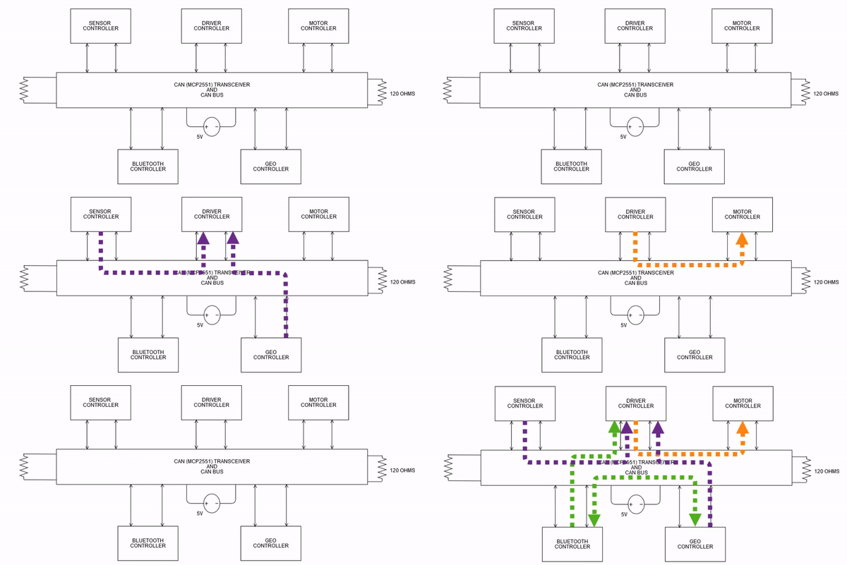
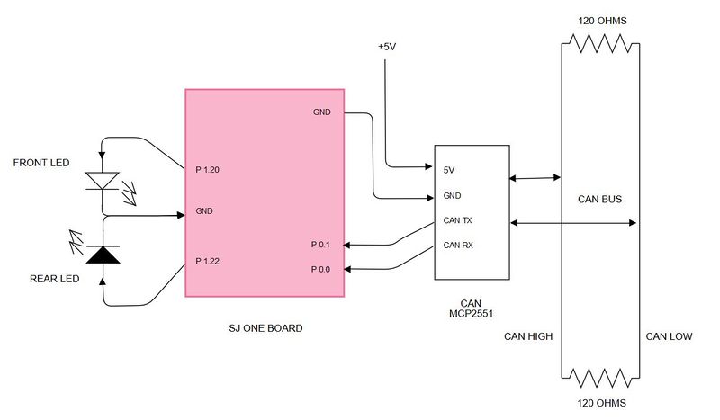
Difference between revisions of "F17: Alpha"
Proj user1 (talk | contribs) (→Implementation) |
Proj user1 (talk | contribs) (→Parts List & Cost) |
||
| (81 intermediate revisions by the same user not shown) | |||
| Line 1: | Line 1: | ||
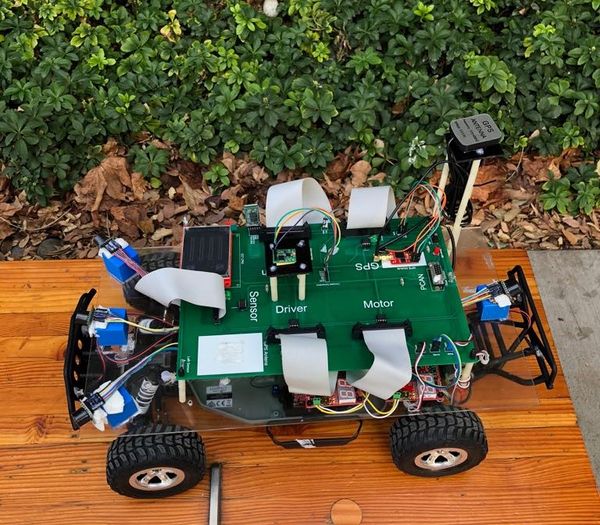
| + | [[File:car_pic_243.jpeg|thumb|600px|ALPHA CAR|right]] | ||
== Project Title == | == Project Title == | ||
Alpha - Self-navigating RC car using CAN communication based on FreeRTOS. | Alpha - Self-navigating RC car using CAN communication based on FreeRTOS. | ||
| Line 9: | Line 10: | ||
* jigar29 | * jigar29 | ||
* kthnptl | * kthnptl | ||
| − | * | + | * rajvisharia |
* ShubhamKulkarni93 | * ShubhamKulkarni93 | ||
* SnehaSharma | * SnehaSharma | ||
| Line 16: | Line 17: | ||
== Abstract == | == Abstract == | ||
| − | The aim of this project is the development of an autonomous RC car which | + | The aim of this project is the development of an autonomous RC car which will navigate from its current location to destination location, avoiding all the obstacles on its way. The car will be integrated with the GPS, Compass, Bluetooth, multiple sensors such as ultrasonic sensors and RPM sensors to fulfill the purpose of navigation, obstacle detection, and avoidance. A Google-map based android application is developed which finds out the shortest path between current location and destination inside SJSU campus and connects to the self-driving RC car via Bluetooth. The car can move along the route provided by the application to reach the destination. Communication between all the modules on the car is done through CAN. Cgreen Unit testing (For C++) and JUnit Test (For Android) is used to improve performance and save time. On-board LEDs, headlights and taillights on the car are used for debugging issues and to get all relevant information about the status of the car, in real time. An LCD is used to give a more detailed information related to the car. |
== Objectives & Introduction == | == Objectives & Introduction == | ||
| Line 24: | Line 25: | ||
The project was divided into six modules: | The project was divided into six modules: | ||
| − | '''1)Sensor Module :''' To detect the distance to an obstacle from the car using ultrasonic sensors. | + | '''1) Sensor Module: ''' To detect the distance to an obstacle from the car using ultrasonic sensors. |
| − | '''2)Motor Module :''' To move the car | + | '''2) Motor Module: ''' To move the car forward and reverse with accurate speed and different steering angle. |
| − | '''3)Geographical Controller :''' To navigate the car in the direction of the destination using current location and heading angle of the car. | + | '''3) Geographical Controller: ''' To navigate the car in the direction of the destination using current location and heading angle of the car. |
| − | '''4)Master Module :''' To make all | + | '''4) Master Module: ''' To make all decisions for the smooth navigation of the car. |
| − | '''5)Communication Bridge Controller & LCD :''' To establish communication between car and android application as well as displaying all the | + | '''5) Communication Bridge Controller & LCD: ''' To establish communication between car and android application as well as displaying all the information of car on LCD. |
Communication between above five modules is established using CAN Bus. | Communication between above five modules is established using CAN Bus. | ||
| − | '''6)Android Application :''' To provide shortest path | + | '''6) Android Application: ''' To provide shortest path navigation inside SJSU campus which communicates to the car using Bluetooth. |
| − | === | + | === Objectives === |
| − | 1) To be able to detect and avoid | + | 1) To be able to detect and avoid the obstacles. |
| − | 2) To be able to move | + | 2) To be able to move at a constant speed, able to increase and decrease speed as per requirement. |
| − | 3) To be able to | + | 3) To be able to navigate from the current location to the destination. |
| − | 4) To be able to communicate with | + | 4) To be able to communicate with the Android application. |
=== Team Members & Responsibilities === | === Team Members & Responsibilities === | ||
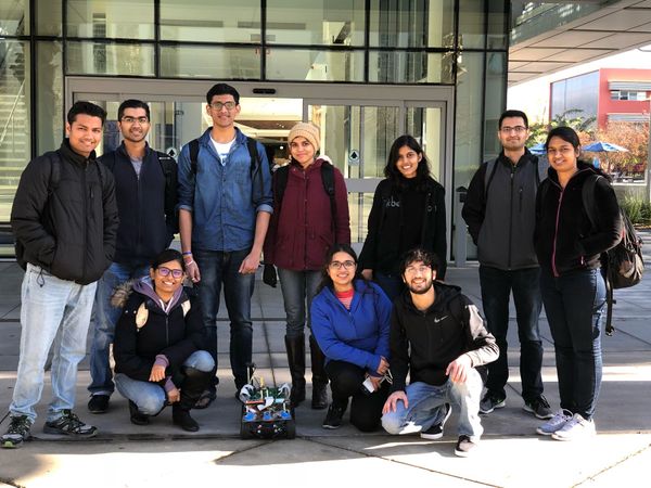
| + | [[File:grp_pic_243.jpeg|thumb|600px|TEAM ALPHA|right]] | ||
* Master Controller | * Master Controller | ||
| − | ** Jigar Agarwal | + | **'''''[https://www.linkedin.com/in/jigaragrawal/ Jigar Agarwal]''''' |
| − | ** Sucheta Iyer | + | **'''''[https://www.linkedin.com/in/sucheta-iyer-a48195100/ Sucheta Iyer]''''' |
* Motor Controller | * Motor Controller | ||
| Line 59: | Line 61: | ||
* Geographical Controller | * Geographical Controller | ||
| − | ** Chhavi Mehta | + | **'''''[https://www.linkedin.com/in/chhavi-mehta-b72a36121 Chhavi Mehta]''''' |
| − | ** Krishna Sai Anirudh Katamreddy | + | **'''''[https://www.linkedin.com/in/krishna-sai-anirudh-katamreddy-92a46193/ Krishna Sai Anirudh Katamreddy]''''' |
* Sensor Controller | * Sensor Controller | ||
| − | ** Sneha Sharma | + | **'''''[https://www.linkedin.com/in/snehasharma15/ Sneha Sharma]''''' |
| − | ** Sushma Macha | + | **'''''[https://www.linkedin.com/in/sushmamacha Sushma Macha]''''' |
* Communication Bridge Controller & LCD | * Communication Bridge Controller & LCD | ||
| − | ** Kathan Patel | + | **'''''[https://www.linkedin.com/in/kathan15/ Kathan Patel]''''' |
| − | ** Sushma Macha | + | **'''''[https://www.linkedin.com/in/sushmamacha Sushma Macha]''''' |
* Android Application | * Android Application | ||
| − | ** Doyal Patel | + | **'''''[https://www.linkedin.com/in/doyal-patel-747a80127/ Doyal Patel]''''' |
| − | ** Sneha Sharma | + | **'''''[https://www.linkedin.com/in/snehasharma15/ Sneha Sharma]''''' |
* Testing | * Testing | ||
| − | ** | + | **'''''[https://www.linkedin.com/in/jigaragrawal/ Jigar Agarwal]''''' |
| − | + | **'''''[https://www.linkedin.com/in/sucheta-iyer-a48195100/ Sucheta Iyer]''''' | |
| − | ** Sucheta Iyer | + | **'''''[https://www.linkedin.com/in/doyal-patel-747a80127/ Doyal Patel]''''' |
| + | <br> | ||
== Schedule == | == Schedule == | ||
| Line 204: | Line 207: | ||
* Make the PCB design for the entire unit. Give extra Vcc and ground pins at the ends for added functionalities like headlights and indicators. | * Make the PCB design for the entire unit. Give extra Vcc and ground pins at the ends for added functionalities like headlights and indicators. | ||
| − | | | + | | Completed |
|- | |- | ||
! scope="row"| 11 | ! scope="row"| 11 | ||
| Line 213: | Line 216: | ||
* Further testing and optimization of the project on campus routes. | * Further testing and optimization of the project on campus routes. | ||
| − | | | + | |Completed |
|- | |- | ||
| − | | | + | ! scope="row"| 12 |
| − | | | + | | 12/20/2017 |
| − | | | + | | 12/20/2017 |
|**************Final Demonstration.*************** | |**************Final Demonstration.*************** | ||
| − | | | + | | Completed |
|- | |- | ||
|} | |} | ||
| Line 229: | Line 232: | ||
! scope="col"| Part Desciption | ! scope="col"| Part Desciption | ||
! scope="col"| Vendor | ! scope="col"| Vendor | ||
| − | |||
! scope="col"| Qty | ! scope="col"| Qty | ||
! scope="col"| Cost | ! scope="col"| Cost | ||
| Line 235: | Line 237: | ||
! scope="row"| 1 | ! scope="row"| 1 | ||
| RC Car | | RC Car | ||
| − | | | + | | Traxxas |
| − | |||
| 1 | | 1 | ||
| − | | | + | | $250.00 |
|- | |- | ||
! scope="row"| 2 | ! scope="row"| 2 | ||
| CAN Transceivers MCP2551-I/P | | CAN Transceivers MCP2551-I/P | ||
| Microchip [http://www.microchip.com/wwwproducts/en/en010405] | | Microchip [http://www.microchip.com/wwwproducts/en/en010405] | ||
| − | |||
| 8 | | 8 | ||
| Free Samples | | Free Samples | ||
| Line 250: | Line 250: | ||
| Sonar Sensor | | Sonar Sensor | ||
| Amazon [https://www.amazon.com/Maxbotix-MB1010-LV-MaxSonar-EZ1-Range-Finder/dp/B00A7YGVJI] | | Amazon [https://www.amazon.com/Maxbotix-MB1010-LV-MaxSonar-EZ1-Range-Finder/dp/B00A7YGVJI] | ||
| − | |||
| 4 | | 4 | ||
| $24.95 | | $24.95 | ||
| Line 256: | Line 255: | ||
! scope="row"| 4 | ! scope="row"| 4 | ||
| Headlights | | Headlights | ||
| − | | | + | | Amazon Prime |
| − | | | + | | 4 |
| − | | | + | | $6.66 |
| − | |||
|- | |- | ||
! scope="row"| 5 | ! scope="row"| 5 | ||
| NiMH Battery | | NiMH Battery | ||
| From seniors | | From seniors | ||
| − | |||
| 2 | | 2 | ||
| − | | | + | | $60.00 |
|- | |- | ||
! scope="row"|6 | ! scope="row"|6 | ||
| Charger for NiMH/NiCd Battery | | Charger for NiMH/NiCd Battery | ||
| From seniors | | From seniors | ||
| − | |||
| 1 | | 1 | ||
| − | | | + | | $15.00 |
|- | |- | ||
! scope="row"| 7 | ! scope="row"| 7 | ||
| Bluetooth (HC-05) | | Bluetooth (HC-05) | ||
| HiLetgo | | HiLetgo | ||
| − | |||
| 1 | | 1 | ||
| − | | | + | | $9.00 |
|- | |- | ||
! scope="row"| 8 | ! scope="row"| 8 | ||
| Graphics LCD Display | | Graphics LCD Display | ||
| 4D systems | | 4D systems | ||
| − | |||
| 1 | | 1 | ||
| − | | 49. | + | | $49.00 |
|- | |- | ||
! scope="row"| 9 | ! scope="row"| 9 | ||
| SJOne Boards | | SJOne Boards | ||
| From Preet | | From Preet | ||
| − | |||
| 4 | | 4 | ||
| − | | 400.00 | + | | $400.00 |
|- | |- | ||
! scope="row"| 10 | ! scope="row"| 10 | ||
| RPM Sensor | | RPM Sensor | ||
| Amazon Prime | | Amazon Prime | ||
| − | |||
| 1 | | 1 | ||
| − | | 25 | + | | $25.00 |
|- | |- | ||
! scope="row"| 11 | ! scope="row"| 11 | ||
| Magnets | | Magnets | ||
| From Seniors | | From Seniors | ||
| − | |||
| 15 | | 15 | ||
| − | | 0.00 | + | | $0.00 |
|- | |- | ||
|} | |} | ||
| + | |||
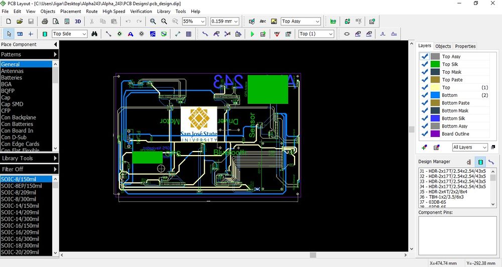
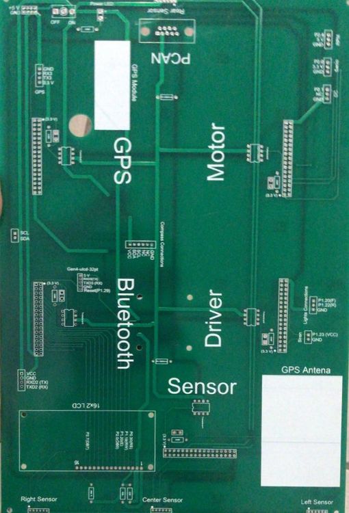
| + | == Printed Circuit Board == | ||
| + | We have designed our own PCB for this project. We used Diptrace software for our design.For fabrication, we sent the Gerber files to PCBway( Situated in China) for further fabrication. The PCB that we designed is a 2 layer PCB. All the components are on the Top Side of the PCB. We only used through-hole components In our PCB. | ||
| + | <br><br><br> | ||
| + | |||
| + | [[File:Example1.jpg|1000x1200px|thumb|center|Software Design Of PCB]] | ||
| + | <gallery mode=packed widths="500px" heights="500px"> | ||
| + | File:Front.jpg|thumb|center|Front View Of PCB | ||
| + | File:rear.jpg|thumb|center|Rear View Of PCB | ||
| + | </gallery> | ||
| + | |||
| + | == DBC File == | ||
| + | [[File:Example26.png| Project DBC File]] | ||
== Sensor Module == | == Sensor Module == | ||
| − | The sensor module refers to the sensors and the embedded board that controls the sensors. In this project we have used four Maxbotix EZ0 ultrasonic sensors. Each of these is mounted in four positions. Three sensors face the front of the car and are positioned in the | + | The sensor module refers to the sensors and the embedded board that controls the sensors. In this project, we have used four Maxbotix EZ0 ultrasonic sensors. Each of these is mounted in four positions. Three sensors face the front of the car and are positioned in the center, the left edge and right edge of the car. One sensor is mounted on the back of the car. |
The main goal of the sensor module is to detect the distance to an obstacle, from the car and provide this information to the driver module so that it can successfully avoid the obstacle. | The main goal of the sensor module is to detect the distance to an obstacle, from the car and provide this information to the driver module so that it can successfully avoid the obstacle. | ||
| Line 324: | Line 328: | ||
The valid sensors output is a value between 6 and 254. This value is in inches and represents the distance to the obstacle, from the sensor. It is to be noted that if the obstacle is closer than 6 inches from the sensor it will not be detected. | The valid sensors output is a value between 6 and 254. This value is in inches and represents the distance to the obstacle, from the sensor. It is to be noted that if the obstacle is closer than 6 inches from the sensor it will not be detected. | ||
| − | The sensor provides output in three forms; As a pulse on the PW pin, where pulse width represents the distance to obstacle; As an analog voltage on the AN pin; As a digital output on the TX pin, in RS-232 format. We have used the PW pin in this project to receive the input from the sensor. | + | The sensor provides output in three forms; As a pulse on the PW pin, where pulse width represents the distance to an obstacle; As an analog voltage on the AN pin; As a digital output on the TX pin, in RS-232 format. We have used the PW pin in this project to receive the input from the sensor. |
| − | It is to be noted that if two sensors which are placed so that their beams/detection areas overlap | + | It is to be noted that if two sensors which are placed so that their beams/detection areas overlap are ranging at the same time, they cause each other interference and hence incorrect values. Hence we trigger each sensor separately one by one so that at any time, only one sensor is ranging. |
| Line 335: | Line 339: | ||
=== Hardware Interface === | === Hardware Interface === | ||
| − | Pin connections for each sensor | + | Pin connections for each sensor are as follows: |
PW (Pin 2) - GPIO Pin configured as interrupt to receive input from sensor | PW (Pin 2) - GPIO Pin configured as interrupt to receive input from sensor | ||
| Line 350: | Line 354: | ||
=== Software Design === | === Software Design === | ||
| − | |||
As described in the previous section, the sensors are triggered one by one to prevent corruption of data. In our implementation the sensors are triggered in the following order: middle, right, left and back. The back and left sensors are triggered together since they would not interfere with each other. | As described in the previous section, the sensors are triggered one by one to prevent corruption of data. In our implementation the sensors are triggered in the following order: middle, right, left and back. The back and left sensors are triggered together since they would not interfere with each other. | ||
| − | Every sensor needs a power up time of 250 ms and some time to calibrate and take the first reading. After this period the sensor can provide a reading every 49 ms. In our implementation, all 4 sensor values are taken every 120 ms and put on the CAN bus. The format of the CAN message is shown in the following snippet taken from the DBC file. It can be observed that the sensor message has a high priority since it is critical to the operation of the car. | + | Every sensor needs a power-up time of 250 ms and some time to calibrate and take the first reading. After this period the sensor can provide a reading every 49 ms. In our implementation, all 4 sensor values are taken every 120 ms and put on the CAN bus. The format of the CAN message is shown in the following snippet taken from the DBC file. It can be observed that the sensor message has a high priority since it is critical to the operation of the car. |
=== Implementation === | === Implementation === | ||
| Line 370: | Line 373: | ||
[[File:243 imp flowchart.png|thumb|600x600px|center|Sensor operation flowchart]] | [[File:243 imp flowchart.png|thumb|600x600px|center|Sensor operation flowchart]] | ||
| − | === | + | === Technical Challenges === |
There were a few difficulties during implementation and testing of the sensors. Lessons learned include the following: | There were a few difficulties during implementation and testing of the sensors. Lessons learned include the following: | ||
| − | 1 | + | '''Challenge 1:''' Research different types of sensors, find out the strengths and weaknesses of each before making a decision. |
| − | 2 | + | '''Challenge 2:''' Ultrasonic sensors need to be slightly tilted upwards when mounted on the car to prevent them from accidentally detecting ground as an obstacle. This becomes especially necessary when testing on a slope/ramp. |
| − | 3 | + | '''Challenge 3:''' Ultrasonic sensors are very sensitive and care needs to be taken while soldering them. Accidental overheating can cause them to be destroyed. |
| − | 4 | + | '''Challenge 4:''' The ultrasonic sensors provide more range when +5V is used as supply rather than +3.3V. |
| − | 5 | + | '''Challenge 5:''' Testing both indoors and outdoors is necessary to check if the sensor readings are accurate in both conditions. |
== Motor Module == | == Motor Module == | ||
Motor module is one of the five controllers used in our self-driving car. Motor controller is responsible for driving the car forward and for steering the vehicle. The motor module has two motors viz.DC motor and Servo motor. DC motor makes the car move forward and reverse. Servo motor steers the car either left or right. Along with the two motors, we have the rpm speed sensor which is interfaced with our controller to control the speed of DC and move the car at the desired speed in Miles per Hour(MPH). | Motor module is one of the five controllers used in our self-driving car. Motor controller is responsible for driving the car forward and for steering the vehicle. The motor module has two motors viz.DC motor and Servo motor. DC motor makes the car move forward and reverse. Servo motor steers the car either left or right. Along with the two motors, we have the rpm speed sensor which is interfaced with our controller to control the speed of DC and move the car at the desired speed in Miles per Hour(MPH). | ||
| − | |||
| − | |||
| − | |||
=== Hardware Design === | === Hardware Design === | ||
| − | The Motor Module consists of 2 motors viz. DC motor and Servo motor controlled by an SJOne board by varying the PWM signals, which is nothing but the duty cycle. PWM stands for pulse-width modulation, a type of digital signal and can be used to control the motors.Along with two motors we have interfaced the RPM sensor with the motor module micro-controller to get the wheel feedback and move our car at a constant speed even if the car is going uphill or downhill. | + | The Motor Module consists of 2 motors viz. DC motor and Servo motor controlled by an SJOne board by varying the PWM signals, which is nothing but the duty cycle. PWM stands for pulse-width modulation, a type of digital signal and can be used to control the motors. Along with two motors, we have interfaced the RPM sensor with the motor module micro-controller to get the wheel feedback and move our car at a constant speed even if the car is going uphill or downhill. |
[[File:Motor module Block diagram.PNG|600px|thumb|center|Block Diagram for Motor module]] | [[File:Motor module Block diagram.PNG|600px|thumb|center|Block Diagram for Motor module]] | ||
| Line 402: | Line 402: | ||
| − | ===== Servo Motor | + | ===== Servo Motor ===== |
[[File:SERVO_MOTOR.gif|right|820x518px|thumb|Varying Duty cycle and PWM waveforms according to steering position]] | [[File:SERVO_MOTOR.gif|right|820x518px|thumb|Varying Duty cycle and PWM waveforms according to steering position]] | ||
| Line 447: | Line 447: | ||
<br> | <br> | ||
| − | ===== DC Motor | + | ===== DC Motor ===== |
[[File:3785_titan_12T.jpg|right|200x200px|thumb|DC motor Traxas#3785_Titan_12T]] | [[File:3785_titan_12T.jpg|right|200x200px|thumb|DC motor Traxas#3785_Titan_12T]] | ||
| Line 453: | Line 453: | ||
Like servo motor, the DC motor was also embedded in the RC car. The DC motor is used to convert an electrical signal into mechanical power. DC motor is controlled in the same manner as the servo motor i.e., by varying the PWM signal. The only difference here is that the PWM signal from the SJOne board is given to an Electronic Speed Controller or ESC. The ESC is used to generate three-phase electric power of low voltage in order to vary the speed of the DC motor. In case of no ESC, the DC motor will either not move or will start moving at full throttle. The RC car DC motor required 7.4V of power supply to work. The maximum speed that can be attained by this DC motor is 31mph. | Like servo motor, the DC motor was also embedded in the RC car. The DC motor is used to convert an electrical signal into mechanical power. DC motor is controlled in the same manner as the servo motor i.e., by varying the PWM signal. The only difference here is that the PWM signal from the SJOne board is given to an Electronic Speed Controller or ESC. The ESC is used to generate three-phase electric power of low voltage in order to vary the speed of the DC motor. In case of no ESC, the DC motor will either not move or will start moving at full throttle. The RC car DC motor required 7.4V of power supply to work. The maximum speed that can be attained by this DC motor is 31mph. | ||
| + | <br> | ||
| + | <br> | ||
| + | <br> | ||
| + | <br> | ||
| + | <br> | ||
| + | <br> | ||
| + | <br> | ||
| + | <br> | ||
=== Software Design === | === Software Design === | ||
| + | [[File:FLOW servo.jpg|thumb|800x800px|left|Servo motor flowchart]] | ||
| − | + | [[File:DC motor Flow chart.jpg|thumb|500x800px|right|DC motor flowchart]] | |
| − | + | <br> | |
| − | + | <br> | |
| − | + | <br> | |
| + | <br> | ||
| + | <br> | ||
| + | <br> | ||
| + | <br> | ||
| + | <br> | ||
| + | <br> | ||
| + | <br> | ||
| + | <br> | ||
| + | <br> | ||
| + | <br> | ||
| + | <br> | ||
| + | <br> | ||
| + | <br> | ||
| + | <br> | ||
| + | <br> | ||
| + | <br> | ||
| + | <br> | ||
| + | <br> | ||
| + | <br> | ||
| + | <br> | ||
| + | <br> | ||
| + | <br> | ||
| + | <br> | ||
| + | <br> | ||
| + | <br> | ||
| + | <br> | ||
| + | <br> | ||
| + | <br> | ||
| + | <br> | ||
| + | <br> | ||
| + | <br> | ||
| + | <br> | ||
| + | <br> | ||
| + | <br> | ||
| + | <br> | ||
| + | <br> | ||
| + | <br> | ||
| + | <br> | ||
| + | <br> | ||
| + | <br> | ||
| + | <br> | ||
| + | <br> | ||
| + | <br> | ||
| − | |||
=== Testing & Technical Challenges === | === Testing & Technical Challenges === | ||
Following were the problems faced and their resolutions: | Following were the problems faced and their resolutions: | ||
| − | '''Problem 1:''' | + | '''Problem 1:''' RPM sensor was not able to detect the magnet fixed on the wheel. |
| − | '''Solution 1:''' | + | '''Solution 1:''' We had to stack together 3 magnets instead of one so that it was just millimeters away from the RPM sensor as well as its magnetic strength increased to be detected accurately by the RPM sensor. |
| − | '''Problem 2:''' | + | '''Problem 2:''' Speed was not accurate with one magnet on the wheel. |
| − | '''Solution 2:''' | + | '''Solution 2:''' Five magnets at an equidistant position from each other were used for better accuracy. More the magnets, better is the accuracy of speed calculation. |
| − | '''Problem 3:''' | + | '''Problem 3:''' In spite of controlling speed using RPM sensor, the car was not in control while on a downhill. |
| − | '''Solution 3:''' | + | '''Solution 3:''' After trying all possible solutions we could think of, we applied a brake momentarily at the start to reduce the sudden increase in PWM and then controlled the car based on the inclination. Also, made sure that if PWM value went below a certain range, then no brake was applied to the car. |
| − | '''Problem 4:''' | + | '''Problem 4:''' The car did not go reverse all of a sudden even with the working code. |
| − | '''Solution 4:''' | + | '''Solution 4:''' When checked with the transmitter/remote, still didn't work. It was found by reading the manual that ESC has 3 modes which can be set by long pressing the power button. And accidentally, ESC was changed to mode 2 where reverse wouldn't work. The car was set back to Mode 1. |
| − | '''Problem 5:''' | + | '''Problem 5:''' Servo and DC motors didn't move even in open surroundings with no obstacles or MIA condition at one instance. |
| − | '''Solution 5 | + | '''Solution 5:''' It was found that the Bluetooth start button was disabled from the Android application. |
| − | |||
| − | |||
| − | |||
| − | |||
| − | |||
| − | |||
| − | |||
| − | |||
| − | |||
| − | |||
== Geographical Controller == | == Geographical Controller == | ||
| Line 512: | Line 553: | ||
Venus638FLPx is used for detecting the location of the car. It returns the NMEA GPS string which needs to be parsed to get the latitude and longitude values from the module. It is a high performance, low cost, single | Venus638FLPx is used for detecting the location of the car. It returns the NMEA GPS string which needs to be parsed to get the latitude and longitude values from the module. It is a high performance, low cost, single | ||
| − | chip GPS receiver that offers very low power consumption, high sensitivity, and best in class signal acquisition and time-to-first-fix performance. | + | chip GPS receiver that offers very low power consumption, high sensitivity, and best in the class signal acquisition and time-to-first-fix performance. |
Features: | Features: | ||
| Line 519: | Line 560: | ||
-148dBm cold start sensitivity | -148dBm cold start sensitivity | ||
-165dBm tracking sensitivity | -165dBm tracking sensitivity | ||
| − | 29 second cold start TTFF | + | 29-second cold start TTFF |
| − | 1 second hot start | + | 1-second hot start |
2.5m accuracy | 2.5m accuracy | ||
67mW full power navigation | 67mW full power navigation | ||
| Line 533: | Line 574: | ||
We have incorporated the I2C interface in which the 'mode' pin of the compass is left unconnected. It has a 28-byte array of registers and compass bearing can be read from 8-bit register 1. | We have incorporated the I2C interface in which the 'mode' pin of the compass is left unconnected. It has a 28-byte array of registers and compass bearing can be read from 8-bit register 1. | ||
| − | Calibration of CMPS11 - We are using switch 1 and switch 2 of the SJOne board for entering and exiting the calibration mode respectively. When switch 1 is pressed, a 3-byte sequence of 0xF0, 0xF5 and 0xF6 is sent to the command register 0 and an led on the module starts blinking indicating the calibration mode. Compass is then slowly rotated in all 3 dimensions to get both negative and positive maximums. Only after the led completely extinguishes, switch 2 is pressed and 0xF8 command is sent to exit the calibration mode. More accurate readings can be achieved by performing calibration meticulously. | + | Calibration of CMPS11 - We are using switch 1 and switch 2 of the SJOne board for entering and exiting the calibration mode respectively. When switch 1 is pressed, a 3-byte sequence of 0xF0, 0xF5 and 0xF6 is sent to the command register 0 and an led on the module starts blinking indicating the calibration mode. Compass is then slowly rotated in all 3 dimensions to get both negative and positive maximums. Only after the led completely extinguishes, switch 2 is pressed and a 0xF8 command is sent to exit the calibration mode. More accurate readings can be achieved by performing calibration meticulously. |
=== Hardware Interface === | === Hardware Interface === | ||
| Line 541: | Line 582: | ||
UART : | UART : | ||
| − | Pin connections for GPS | + | Pin connections for GPS are as follows: |
VCC (Pin 1) - +5V | VCC (Pin 1) - +5V | ||
| Line 553: | Line 594: | ||
I2C: | I2C: | ||
| − | Pin connections for compass | + | Pin connections for compass are as follows: |
VCC (Pin 1) - +3.3V | VCC (Pin 1) - +3.3V | ||
| Line 574: | Line 615: | ||
STEP 2: Read satellite count from the GPS sensor to enable GPS lock. | STEP 2: Read satellite count from the GPS sensor to enable GPS lock. | ||
| − | STEP 2: Get heading angle from compass through I2C, compass can be calibrated on pressing switch 3 and 4 at the same time and can be stopped on pressing switch 1. | + | STEP 2: Get heading angle from compass through I2C, the compass can be calibrated on pressing switch 3 and 4 at the same time and can be stopped on pressing switch 1. |
STEP 3: Sending GPS heartbeat message on CAN bus to master, so that master knows that GPS module is connected. | STEP 3: Sending GPS heartbeat message on CAN bus to master, so that master knows that GPS module is connected. | ||
| Line 588: | Line 629: | ||
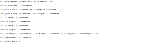
STEP 7: Computing the distance between the current location and the destination location. | STEP 7: Computing the distance between the current location and the destination location. | ||
| − | STEP 8: If obtained distance is less than 5 meters then a message is sent to master as well as bridge controller, so that bridge controller can send the next checkpoint. | + | STEP 8: If the obtained distance is less than 5 meters then a message is sent to master as well as bridge controller, so that bridge controller can send the next checkpoint. |
STEP 9: If all the checkpoints are done then that is the final destination, and bridge controller will not send any new location, so master should stop the car on receiving the car arrived message. | STEP 9: If all the checkpoints are done then that is the final destination, and bridge controller will not send any new location, so master should stop the car on receiving the car arrived message. | ||
| Line 594: | Line 635: | ||
STEP 10: Finding the difference between heading angle and bearing angle, and realizing how much does the car should turn to navigate towards the destination. | STEP 10: Finding the difference between heading angle and bearing angle, and realizing how much does the car should turn to navigate towards the destination. | ||
| − | STEP 11: Sending a car turn direction message to the master module, so that master module sends the message to motor module to set a | + | STEP 11: Sending a car turn direction message to the master module, so that master module sends the message to the motor module to set a PWM frequency, depending on the message sent, to turn the car. |
=== Implementation === | === Implementation === | ||
| Line 600: | Line 641: | ||
'''Formulae used: ''' | '''Formulae used: ''' | ||
| − | On obtaining the current latitude and longitude position, and destination latitude and longitude position should be determined from CAN message sent by bridge ( | + | On obtaining the current latitude and longitude position, and destination latitude and longitude position should be determined from CAN message sent by bridge (Bluetooth) module. Bearing angle has to be computed from the obtained current location and destination location. |
| − | '''Bearing angle -''' Bearing angle is the angle between the direction towards the destination from the current location with respect to north. The bearing angle range is | + | '''Bearing angle -''' Bearing angle is the angle between the direction towards the destination from the current location with respect to north. The bearing angle range is from 0 to 359. |
Both bearing and heading angle’s should have the same range, can be from -180 to +180 or 0 to 360, we are using 0 to 360. | Both bearing and heading angle’s should have the same range, can be from -180 to +180 or 0 to 360, we are using 0 to 360. | ||
| Line 608: | Line 649: | ||
[[File:CMPE243_Alpha_bearing.png|600x600px|thumb|center|Bearing Angle Computation]] | [[File:CMPE243_Alpha_bearing.png|600x600px|thumb|center|Bearing Angle Computation]] | ||
| − | '''Degrees -''' We need to compute the angle that the car has to turn from its current direction towards the destination, from the | + | '''Degrees -''' We need to compute the angle that the car has to turn from its current direction towards the destination, from the obtained bearing angle(angle at which the car should go with respect to north to reach the destination) and heading angle (angle at which our car is going currently with respect to north). |
Degree = Heading angle - Bearing angle | Degree = Heading angle - Bearing angle | ||
| Line 630: | Line 671: | ||
| − | '''Problem 2:''' There was significant delay(5-10 seconds, approximately) in the getting the latitude and longitude values while the car is moving. | + | '''Problem 2:''' There was a significant delay(5-10 seconds, approximately) in the getting the latitude and longitude values while the car is moving. |
'''Solution 2:''' The receive queue/buffer size of UART should be kept minimum. | '''Solution 2:''' The receive queue/buffer size of UART should be kept minimum. | ||
| Line 640: | Line 681: | ||
== Communication Bridge Controller & LCD == | == Communication Bridge Controller & LCD == | ||
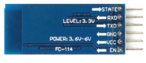
| − | The purpose of Communication Bridge Controller is to establish communication between Andriod app and Car via | + | The purpose of Communication Bridge Controller is to establish communication between Andriod app and Car via the Bluetooth communication protocol. This ECU sends the updated checkpoints to Geo Controller at a particular instance when the car reaches at one checkpoint and sends the current location of the car to the phone so the tracking of the car on-road becomes easy. The Communication Bridge Controller also displays the Current location, Sensor readings, Car Speed on graphics LCD. |
=== Hardware Design === | === Hardware Design === | ||
| Line 670: | Line 711: | ||
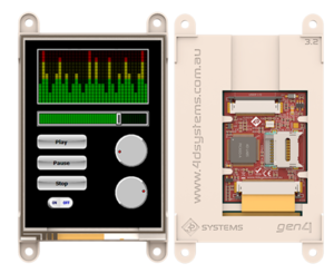
[[File:CMPE243_Alpha_Gen4_LCD.png|thumb|300x300px|right|Graphics LCD from 4D systems]] | [[File:CMPE243_Alpha_Gen4_LCD.png|thumb|300x300px|right|Graphics LCD from 4D systems]] | ||
| − | This project uses gen4 3.2” Picaso Integrated Display Module by 4D Systems. This LCD comes with resistive touch. It is powered by the well-known 4D Systems Picaso Graphics Processor, which offers wide range of functionality and options for any Designer/Integrator. We have used Workshop4 IDE and its Visi-Genie development environment for interfacing the LCD with | + | This project uses gen4 3.2” Picaso Integrated Display Module by 4D Systems. This LCD comes with resistive touch. It is powered by the well-known 4D Systems Picaso Graphics Processor, which offers a wide range of functionality and options for any Designer/Integrator. We have used Workshop4 IDE and its Visi-Genie development environment for interfacing the LCD with the controller. |
''' Specifications and Features ''' | ''' Specifications and Features ''' | ||
| Line 680: | Line 721: | ||
* 2 x Asynchronous hardware serial ports (COM0, COM1), TTL interface, with 300 to 600K baud. | * 2 x Asynchronous hardware serial ports (COM0, COM1), TTL interface, with 300 to 600K baud. | ||
* 1 x I2C interface (Master). | * 1 x I2C interface (Master). | ||
| − | * 8 x 16 bit timers with 1 millisecond resolution. | + | * 8 x 16-bit timers with 1-millisecond resolution. |
* 13 x General Purpose I/O pins. Supports fast 8-bit parallel data transfer through Upper 8 bits. | * 13 x General Purpose I/O pins. Supports fast 8-bit parallel data transfer through Upper 8 bits. | ||
| − | * 30pin FPC connection, for all signals, power, communications, GPIO and programming. | + | * 30pin FPC connection, for all signals, power, communications, GPIO, and programming. |
* On-board latch type micro-SD memory card connector for multimedia storage and data logging purposes. | * On-board latch type micro-SD memory card connector for multimedia storage and data logging purposes. | ||
| − | * DOS compatible file access (FAT16 format) as well as low level access to card memory. | + | * DOS compatible file access (FAT16 format) as well as low-level access to card memory. |
=== Hardware Interface === | === Hardware Interface === | ||
[[File:CMPE243_Alpha_Comm_Bridge_Hardware_int.png|thumb|700x700px|center| Communication Hardware Interface ]] | [[File:CMPE243_Alpha_Comm_Bridge_Hardware_int.png|thumb|700x700px|center| Communication Hardware Interface ]] | ||
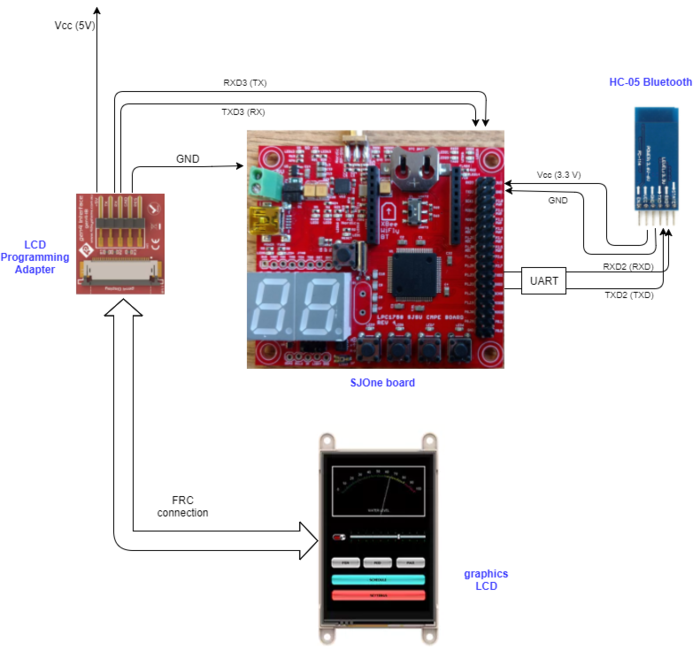
| − | The Communication Bridge Controller is the interface of communication between user and the car. The ECU is interfaced with Bluetooth via UART and with graphics LCD via UART. The Communication Bridge Controller displays the messages on LCD. This section details the designs of the hardware components used for the communication and display. Android app routes the car. | + | The Communication Bridge Controller is the interface of communication between the user and the car. The ECU is interfaced with Bluetooth via UART and with graphics LCD via UART. The Communication Bridge Controller displays the messages on LCD. This section details the designs of the hardware components used for the communication and display. Android app routes the car. |
| Line 698: | Line 739: | ||
* Step 1: Initialize the CAN controller, UART2 for Bluetooth communication, UART3 for graphics LCD, setting appropriate queue size for the UART and CAN communication. | * Step 1: Initialize the CAN controller, UART2 for Bluetooth communication, UART3 for graphics LCD, setting appropriate queue size for the UART and CAN communication. | ||
* Step 2: For UART2, read the characters from the queue to decode the type of value. The string type is indicated by the starting character. | * Step 2: For UART2, read the characters from the queue to decode the type of value. The string type is indicated by the starting character. | ||
| − | * Step 3: Convert the string to appropriate message, and store correctly. So after the conversion the value can be either START_STOP, CHECKPOINTS_COUNT or LATITUDE_LONGITUDE. | + | * Step 3: Convert the string to appropriate message, and store correctly. So after the conversion, the value can be either START_STOP, CHECKPOINTS_COUNT or LATITUDE_LONGITUDE. |
| − | * Step 4: For the simplicity before reading the checkpoints the START_STOP bit is set to Zero and after reading all the checkpoints the START_STOP bit is set to One to Start the Car. | + | * Step 4: For the simplicity, before reading the checkpoints the START_STOP bit is set to Zero and after reading all the checkpoints the START_STOP bit is set to One to Start the Car. |
| − | * Step 5: The car is running now to reach to the first checkpoint values. As the Car reaches in the suitable range of the location, the Communication Bridge ECU sends next checkpoint. Otherwise it keeps on transmitting the checkpoint yet to reach. | + | * Step 5: The car is running now to reach to the first checkpoint values. As the Car reaches in the suitable range of the location, the Communication Bridge ECU sends next checkpoint. Otherwise, it keeps on transmitting the checkpoint yet to reach. |
* Step 6: Parallel with the wireless communication. The UART3 queue is getting the messages from CAN bus. | * Step 6: Parallel with the wireless communication. The UART3 queue is getting the messages from CAN bus. | ||
* Step 7: Calculate the checksum of the messages to display on LCD and Display important values like CURRENT_GPS_LOCATION, CAR_SPEED, GPS_BEARING, GPS_HEADING_ANGLE, DISTANCE_to_Destination, and CAR_TURN_ANGLE_Direction. | * Step 7: Calculate the checksum of the messages to display on LCD and Display important values like CURRENT_GPS_LOCATION, CAR_SPEED, GPS_BEARING, GPS_HEADING_ANGLE, DISTANCE_to_Destination, and CAR_TURN_ANGLE_Direction. | ||
| Line 707: | Line 748: | ||
=== Testing & Technical Challenges === | === Testing & Technical Challenges === | ||
| − | 1 | + | '''Problem 1:'''The first problem we had was to read the data from the queue. Some part of actual transmitted data from Android phones was not at all received in the queue. <br> |
| − | + | '''Solution 1:'''We changed the timeout value and handled the newline character while reading data. | |
| − | |||
| − | |||
| − | |||
| + | '''Problem 2:'''The second issue we had was that our START_STOP bit was dependent on "validate and store" function which if the START_STOP bit was not received, the default value | ||
| + | of zero was passed on the bus and that falsely stopped the car.<br> | ||
| + | '''Solution 2:'''We transmitted the START_STOP bit only when we receive it, and not otherwise. | ||
== Master Module == | == Master Module == | ||
| Line 803: | Line 844: | ||
=== Software Design === | === Software Design === | ||
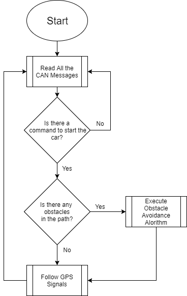
| − | The software flow of the master module is as shown in the following image. Let's get a brief idea of how it | + | The software flow of the master module is as shown in the following image. Let's get a brief idea of how it works, |
| + | 1) In the beginning, all the CAN messages are received they are decoded according to the DBC file.<br> | ||
| + | |||
| + | 2) The android application provides the start and the stop commands for the car to get started or to be stopped when the car is stopped or running respectively.The car will not move until it receives the start signal from the android app. If it doesn't get the start signal from the app it will keep on reading CAN messages at 100Hz periodically. <br> | ||
| + | |||
| + | 3) First of all, after getting the start signal from the app it will check for the obstacles in the path where it is currently facing and if there are no obstacles in the path it will follow the GPS signals and move in the particular direction given by the GPS module. | ||
| + | |||
| + | 4) Here we have given obstacle avoidance a higher priority than the GPS signal. If there are no obstacles then and only then it will follow GPS signals otherwise it will perform obstacle avoidance first. <br> | ||
| Line 813: | Line 861: | ||
* Obstacle Avoidance <br /> | * Obstacle Avoidance <br /> | ||
| − | :Obstacle avoidance algorithm takes care of all the obstacles and moving direction of the car. Obstacle avoidance sends signals to move the car in a certain direction. | + | : Obstacle avoidance algorithm takes care of all the obstacles and moving direction of the car. Obstacle avoidance sends signals to move the car in a certain direction. |
* Motor Commands Generator<br /> | * Motor Commands Generator<br /> | ||
* Indicators Controller | * Indicators Controller | ||
| Line 819: | Line 867: | ||
'''Overview of modules''' | '''Overview of modules''' | ||
:'''Obstacle Avoidance'''<br /> | :'''Obstacle Avoidance'''<br /> | ||
| − | :Obstacle avoidance algorithm is the essence if the driver module. It takes care of all the obstacles that come in between the path and avoids the car from colliding or hurting someone. | + | : Obstacle avoidance algorithm is the essence if the driver module. It takes care of all the obstacles that come in between the path and avoids the car from colliding or hurting someone. |
::'''Some properties of the obstacle avoidance algorithm''', | ::'''Some properties of the obstacle avoidance algorithm''', | ||
| Line 833: | Line 881: | ||
:'''Let's peek more into the working of obstacle avoidance algorithm''', | :'''Let's peek more into the working of obstacle avoidance algorithm''', | ||
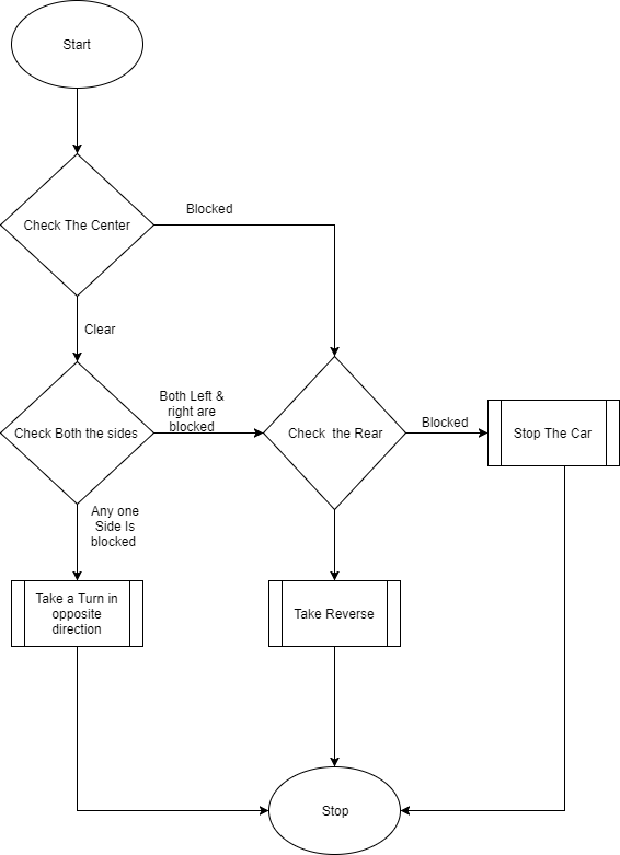
| − | :Obstacle avoidance algorithm is written based on the following state diagram. It keeps on checking the center sensor at the beginning. If the center sensor is sensing an object there is no way we can go further as the car may collide with an obstacle if it detects an obstacle. So, in this case, the car will check whether there is an object in the back or not if the back is also blocked the car will stop at the position. If the rear is not blocked it will take reverse until the front is unblocked. If the center direction is not blocked it will go straight in this case and keep on checking side sensors, if any one of the direction is blocked it will move in the opposite direction. If both the side sensors are blocked then the car will go into reverse condition as it does not have any front direction to go. If the rear is blocked during this operation the car will be stopped at that position, and if not it will take reverse until font direction is clear. If none of the direction is blocked it will always follow the GPS directions sent by GPS module. | + | : Obstacle avoidance algorithm is written based on the following state diagram. It keeps on checking the center sensor at the beginning. If the center sensor is sensing an object there is no way we can go further as the car may collide with an obstacle if it detects an obstacle. So, in this case, the car will check whether there is an object in the back or not if the back is also blocked the car will stop at the position. If the rear is not blocked it will take reverse until the front is unblocked. If the center direction is not blocked it will go straight in this case and keep on checking side sensors, if any one of the direction is blocked it will move in the opposite direction. If both the side sensors are blocked then the car will go into reverse condition as it does not have any front direction to go. If the rear is blocked during this operation the car will be stopped at that position, and if not it will take reverse until font direction is clear. If none of the direction is blocked it will always follow the GPS directions sent by GPS module. |
| Line 840: | Line 888: | ||
:'''Motor Commands Generator''' | :'''Motor Commands Generator''' | ||
| − | :This module is responsible for sending all the actions taken by obstacle avoidance to the motor. | + | : This module is responsible for sending all the actions taken by obstacle avoidance to the motor. |
| − | :It sends following commands to the motor module at the execution of the obstacle avoidance algorithm. | + | : It sends following commands to the motor module at the execution of the obstacle avoidance algorithm. |
:*Angle at which the car should move | :*Angle at which the car should move | ||
:*Driving speed at which the motors should be driven | :*Driving speed at which the motors should be driven | ||
:*Direction in which the car should go(Reverse or Forward) | :*Direction in which the car should go(Reverse or Forward) | ||
| − | :It frames this messages into a structure and sends to the motor to take control accordingly. | + | : It frames this messages into a structure and sends to the motor to take control accordingly. |
:'''Indicator Controller '''<br /> | :'''Indicator Controller '''<br /> | ||
| Line 875: | Line 923: | ||
|- | |- | ||
|} | |} | ||
| − | |||
| − | |||
== Android Application == | == Android Application == | ||
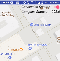
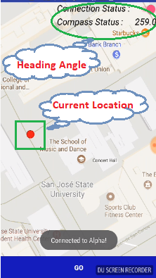
| − | A | + | A google map-based Android application was developed to provide the required information to our self-navigating car, Alpha to reach destination. The information includes the routing information between the source and the destination as well as a software-based command to start and to stop the car. This application also displays information regarding the current position and heading angle of Alpha. |
=== Hardware Interface === | === Hardware Interface === | ||
| − | Image of Interface between android app and | + | Image of Interface between the android app and Bluetooth module is as shown. It has been explained in detail in the Bluetooth Module section. |
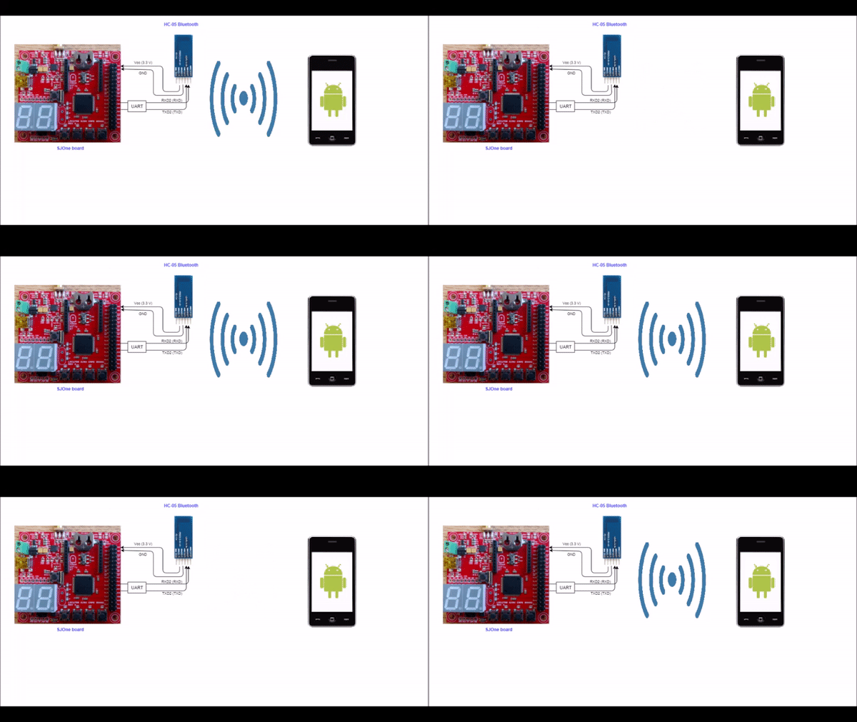
| − | [[File:Interface.gif|Center|none|Interface between android and | + | [[File:Interface.gif|Center|none|Interface between android and Bluetooth module on car]] |
=== Software Design === | === Software Design === | ||
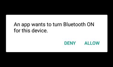
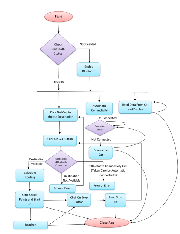
1. '''Bluetooth:''' Bluetooth allows to wirelessly exchange data with another Bluetooth device. Here, we are using Bluetooth to communicate our self-driving car with our Android application. | 1. '''Bluetooth:''' Bluetooth allows to wirelessly exchange data with another Bluetooth device. Here, we are using Bluetooth to communicate our self-driving car with our Android application. | ||
| Line 893: | Line 939: | ||
</gallery> | </gallery> | ||
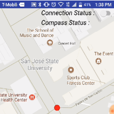
| − | : 1.2. Connect to Bluetooth on Car: A new Socket was created using UUID of Bluetooth device on Alpha. A connection request is sent by calling a connect method created on the socket. Here, "Connect" is the blocking call which will return if the connection request is accepted and the connection is established or an exception will be thrown. To establish an automatic connection between Alpha and the mobile device, a separate thread was created which will continuously check the connection and try to make a connection in case Bluetooth on car is not connected. A connection indicator shows the current connection status. | + | : 1.2. Connect to Bluetooth on Car: A new Socket was created using UUID of Bluetooth device on Alpha. A connection request is sent by calling a connect method created on the socket. Here, "Connect" is the blocking call which will return if the connection request is accepted and the connection is established or an exception will be thrown. To establish an automatic connection between Alpha and the mobile device, a separate thread was created which will continuously check the connection and try to make a connection in case Bluetooth on the car is not connected. A connection indicator shows the current connection status. |
<gallery mode=packed widths="300px" heights="200px"> | <gallery mode=packed widths="300px" heights="200px"> | ||
| Line 905: | Line 951: | ||
: 1.4. Write to Alpha: Write the data in the output stream so that it can be available to Alpha. In this application Start bit, Stop bit and the routing checkpoints are sent to move the car. | : 1.4. Write to Alpha: Write the data in the output stream so that it can be available to Alpha. In this application Start bit, Stop bit and the routing checkpoints are sent to move the car. | ||
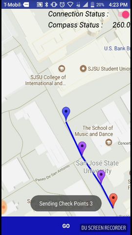
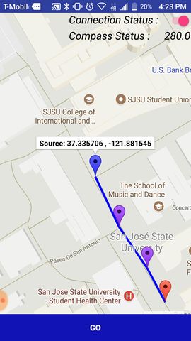
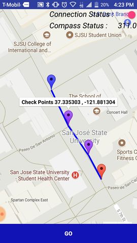
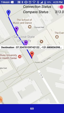
| − | 2. '''Routing Algorithm:''' Dijkstra Routing Algorithm is used to calcite shortest path algorithm between source and destination. | + | 2. '''Routing Algorithm:''' Dijkstra Routing Algorithm is used to calcite shortest path algorithm between source and destination. Checkpoints are taken inside San Jose State University. Latitude and Longitude of each checkpoint are considered as a node of the directed graph. The routing path is stored as an array of checkpoints and sent to the car using Bluetooth. On the map, the routing is shown by blue line which connects to all checkpoints. All checkpoints between the cent location and the destination location are shown by violet colored markers, source location is shown by blue marker and destination is shown by red marker in routing path. |
<gallery mode=packed widths="160px" heights="320px"> | <gallery mode=packed widths="160px" heights="320px"> | ||
File:routing1.jpeg|thumb|Routing path | File:routing1.jpeg|thumb|Routing path | ||
File:routing4.jpeg|thumb|Source Node Indicator with location longitde and latitude. | File:routing4.jpeg|thumb|Source Node Indicator with location longitde and latitude. | ||
| − | File:routing2.jpeg|thumb|Check point Indicator with location | + | File:routing2.jpeg|thumb|Check point Indicator with location longitude and latitude. |
| − | File:routing3.jpeg|thumb|Destination Node Indicator with location | + | File:routing3.jpeg|thumb|Destination Node Indicator with location longitude and latitude. |
</gallery> | </gallery> | ||
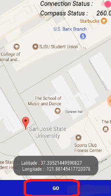
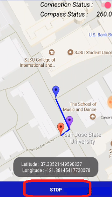
| − | 3. '''Start and Stop:''' Command to start the car and stop the car provided by android | + | 3. '''Start and Stop:''' Command to start the car and stop the car provided by the android application. Here, for both command, a single button is used as start and stop are alternative activity. Once the car is started by pressing on "GO" button on the application, the button on the app will convert in "STOP" button. A voice command indication is provided to Start and to stop. |
<gallery mode=packed widths="160px" heights="320px"> | <gallery mode=packed widths="160px" heights="320px"> | ||
File:Start.png|thumb|left|none|Before Start. | File:Start.png|thumb|left|none|Before Start. | ||
| Line 931: | Line 977: | ||
2. Fork a child thread for automatic connection to the car’s Bluetooth module. | 2. Fork a child thread for automatic connection to the car’s Bluetooth module. | ||
| − | 3. Fork a child thread to read data from the car continuously | + | 3. Fork a child thread to read data from the car continuously from the Bluetooth connection. |
| − | 4. Get the Destination from ‘On click’ method on map. | + | 4. Get the Destination from ‘On click’ method on the map. |
5. On clicking on Go Button | 5. On clicking on Go Button | ||
| Line 943: | Line 989: | ||
::I. Get current location latitude and longitude and save as source. | ::I. Get current location latitude and longitude and save as source. | ||
::II. Calculate routing path using Dijkstra routing algorithm. | ::II. Calculate routing path using Dijkstra routing algorithm. | ||
| − | ::III. Send all | + | ::III. Send all checkpoints to the car using Bluetooth. |
| − | ::IV. Send start message to car | + | ::IV. Send start message to the car via Bluetooth. |
| − | 6. On clicking on Stop Button send stop message to car using Bluetooth. | + | 6. On clicking on Stop Button send stop message to the car using Bluetooth. |
'''Algorithm For Automatic Connection Thread:''' | '''Algorithm For Automatic Connection Thread:''' | ||
| − | 1. If Connection to car is available go to sleep. | + | 1. If Connection to car is available, go to sleep. |
2. Else | 2. Else | ||
:Delete Old socket. | :Delete Old socket. | ||
| − | :Create new socket and send connection request to connect. | + | :Create a new socket and send the connection request to connect. |
:Go to sleep. | :Go to sleep. | ||
| Line 963: | Line 1,009: | ||
'''Algorithm For Read data From Bluetooth Continuously:'''' | '''Algorithm For Read data From Bluetooth Continuously:'''' | ||
| − | 1. Read data from Bluetooth buffer. | + | 1. Read data from the Bluetooth buffer. |
2. Convert data to Current Location and Compass Angle. | 2. Convert data to Current Location and Compass Angle. | ||
| Line 969: | Line 1,015: | ||
3. Display Current Location and Compass Angle on the Display Screen. | 3. Display Current Location and Compass Angle on the Display Screen. | ||
| − | 4. Repeat Step 1 to Step 4 till app is not | + | 4. Repeat Step 1 to Step 4 till app is not destroyed. |
'''Flowchart :''' | '''Flowchart :''' | ||
| Line 976: | Line 1,022: | ||
=== Testing & Technical Challenges === | === Testing & Technical Challenges === | ||
| − | 1. Automatic connection to | + | 1. Automatic connection to Bluetooth: In case of Bluetooth connectivity lost while trying to reconnect using the same Socket was not connecting to Bluetooth again. |
| − | |||
| − | |||
| − | + | Solution: If connection lost between the Android app and Bluetooth a new Socket should create and try to connect using newly created socket. As, now old socket is not used delete old socket. | |
| − | + | 2. Routing Algorithm: There are many shortest path algorithm available which move from one checkpoint to another checkpoint in the map.(Logically all points on the map cannot be checkpoints.) In the application, current checkpoint and destination may not be from the checkpoint which is taken. | |
| − | + | Solution: Make an algorithm to find the nearest checkpoint from the source towards the destination and connect source node to this checkpoint. In the same manner, Find nearest checkpoint from Destination towards the source and connect destination to this checkpoint. Calculate shortest path between these two checkpoint using Disktera's algorithm. | |
| − | |||
| − | |||
| + | 3. Adding Checkpoints: Checkpoint taken by the normal view of google map were not accurate. | ||
| + | Solution: All the checkpoints taken using satellite view of google map and accuracy confirmed by the reading from GPS used by the car. | ||
== Conclusion == | == Conclusion == | ||
| − | We were able to successfully navigate our car to the destination marked in our Android application by avoiding any obstacle in its path. This project gave us a real-world project experience. It helped us gain a working knowledge of CAN bus and communication, interfacing various components such as motors, GPS, Bluetooth and ultrasonic sensors along with some knowledge regarding pulse width modulation (PWM), UART, I2C. | + | We were able to successfully navigate our car to the destination location marked in our Android application by avoiding any obstacle that came in its path. This project gave us a real-world project experience. It helped us gain a working knowledge of CAN bus and communication, interfacing various components such as motors, GPS, Bluetooth and ultrasonic sensors along with some knowledge regarding pulse width modulation (PWM), UART, I2C. This course and project also gave us a deep understanding of FreeRTOS, Android, Unit testing and Git. Along the course of the project, we faced many hardware and software issues, especially while integrating a new module into the existing working solution. But, in spite of all the difficulties, we were able to achieve our goal with the help of proper understanding and teamwork. Working in a group of 10 and managing schedules and GIT branches to cover 5 different modules, it felt as if we were doing an internship. Overall, it was a great learning experience which molded us into better than what we were before we started. |
| − | + | === Project Video === | |
| − | + | [https://youtu.be/_qbkcK2EvfM/ Alpha Team Youtube Video] | |
| − | |||
=== Project Source Code === | === Project Source Code === | ||
| Line 1,008: | Line 1,051: | ||
[1] Preetpal Kang's lecture notes of CMPE 243, Computer Engineering, San Jose State University, Aug-Dec 2017. | [1] Preetpal Kang's lecture notes of CMPE 243, Computer Engineering, San Jose State University, Aug-Dec 2017. | ||
| − | [2] [https://en.wikipedia.org/wiki/Dijkstra%27s_algorithm/ Routing Guide] | + | [2] [http://ww1.microchip.com/downloads/en/DeviceDoc/20001667G.pdf CAN Datasheet] |
| + | |||
| + | [3] [http://www.electronicaestudio.com/docs/istd016A.pdf HC-05 Datasheet] | ||
| + | |||
| + | [4] [https://www.maxbotix.com/documents/LV-MaxSonar-EZ_Datasheet.pdf Ultrasonic sensor datasheet] | ||
| + | |||
| + | [5] [https://en.wikipedia.org/wiki/Dijkstra%27s_algorithm/ Routing Guide] | ||
| + | |||
| + | [6] [https://developer.android.com/ Android Development Guide] | ||
| + | |||
| + | [7] [https://traxxas.com/ Traxxas - RC Car & Forum] | ||
| − | [ | + | [8] [https://cdn.sparkfun.com/datasheets/Sensors/GPS/Venus638FLPx.pdf Venus638FLPx GPS datasheet] |
| − | [ | + | [9] [https://www.robot-electronics.co.uk/htm/cmps11i2c.htm CMPS11 datasheet] |
Latest revision as of 07:07, 12 January 2018
Contents
Project Title
Alpha - Self-navigating RC car using CAN communication based on FreeRTOS.
Git Link - ALPHA
Git Users:
- Anirudh1313
- chhavi17
- DoyalPatel
- jigar29
- kthnptl
- rajvisharia
- ShubhamKulkarni93
- SnehaSharma
- SushmaSJSU
- SuchetaCiyer
Abstract
The aim of this project is the development of an autonomous RC car which will navigate from its current location to destination location, avoiding all the obstacles on its way. The car will be integrated with the GPS, Compass, Bluetooth, multiple sensors such as ultrasonic sensors and RPM sensors to fulfill the purpose of navigation, obstacle detection, and avoidance. A Google-map based android application is developed which finds out the shortest path between current location and destination inside SJSU campus and connects to the self-driving RC car via Bluetooth. The car can move along the route provided by the application to reach the destination. Communication between all the modules on the car is done through CAN. Cgreen Unit testing (For C++) and JUnit Test (For Android) is used to improve performance and save time. On-board LEDs, headlights and taillights on the car are used for debugging issues and to get all relevant information about the status of the car, in real time. An LCD is used to give a more detailed information related to the car.
Objectives & Introduction
Introduction
The project was divided into six modules:
1) Sensor Module: To detect the distance to an obstacle from the car using ultrasonic sensors.
2) Motor Module: To move the car forward and reverse with accurate speed and different steering angle.
3) Geographical Controller: To navigate the car in the direction of the destination using current location and heading angle of the car.
4) Master Module: To make all decisions for the smooth navigation of the car.
5) Communication Bridge Controller & LCD: To establish communication between car and android application as well as displaying all the information of car on LCD.
Communication between above five modules is established using CAN Bus.
6) Android Application: To provide shortest path navigation inside SJSU campus which communicates to the car using Bluetooth.
Objectives
1) To be able to detect and avoid the obstacles.
2) To be able to move at a constant speed, able to increase and decrease speed as per requirement.
3) To be able to navigate from the current location to the destination.
4) To be able to communicate with the Android application.
Team Members & Responsibilities
- Master Controller
- Motor Controller
- Geographical Controller
- Sensor Controller
- Communication Bridge Controller & LCD
- Android Application
- Testing
Schedule
| Week# | Start Date | End Date | Task | Status |
|---|---|---|---|---|
| 1 | 09/15/2017 | 09/16/2017 |
|
Completed |
| 2 | 09/17/2017 | 10/03/2017 |
|
Completed |
| 3 | 10/04/2017 | 10/10/2017 |
|
Completed |
| 4 | 10/11/2017 | 10/17/2017 |
|
Completed |
| 5 | 10/18/2017 | 10/24/2017 |
|
Completed |
| 6 | 10/25/2017 | 10/31/2017 |
|
Completed |
| 7 | 11/01/2017 | 11/07/2017 |
|
Completed |
| 8 | 11/08/2017 | 11/14/2017 |
|
Completed |
| 9 | 11/15/2017 | 11/21/2017 |
|
Completed |
| 10 | 11/22/2017 | 11/29/2017 |
|
Completed |
| 11 | 11/30/2017 | 12/14/2017 |
|
Completed |
| 12 | 12/20/2017 | 12/20/2017 | **************Final Demonstration.*************** | Completed |
Parts List & Cost
| Item# | Part Desciption | Vendor | Qty | Cost |
|---|---|---|---|---|
| 1 | RC Car | Traxxas | 1 | $250.00 |
| 2 | CAN Transceivers MCP2551-I/P | Microchip [1] | 8 | Free Samples |
| 3 | Sonar Sensor | Amazon [2] | 4 | $24.95 |
| 4 | Headlights | Amazon Prime | 4 | $6.66 |
| 5 | NiMH Battery | From seniors | 2 | $60.00 |
| 6 | Charger for NiMH/NiCd Battery | From seniors | 1 | $15.00 |
| 7 | Bluetooth (HC-05) | HiLetgo | 1 | $9.00 |
| 8 | Graphics LCD Display | 4D systems | 1 | $49.00 |
| 9 | SJOne Boards | From Preet | 4 | $400.00 |
| 10 | RPM Sensor | Amazon Prime | 1 | $25.00 |
| 11 | Magnets | From Seniors | 15 | $0.00 |
Printed Circuit Board
We have designed our own PCB for this project. We used Diptrace software for our design.For fabrication, we sent the Gerber files to PCBway( Situated in China) for further fabrication. The PCB that we designed is a 2 layer PCB. All the components are on the Top Side of the PCB. We only used through-hole components In our PCB.
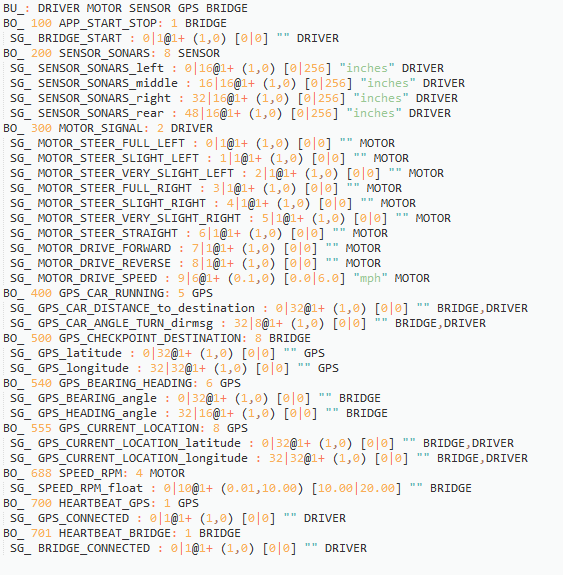
DBC File
Sensor Module
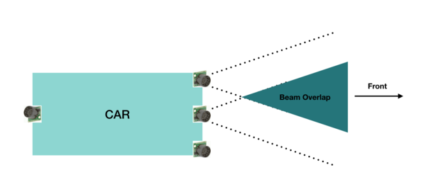
The sensor module refers to the sensors and the embedded board that controls the sensors. In this project, we have used four Maxbotix EZ0 ultrasonic sensors. Each of these is mounted in four positions. Three sensors face the front of the car and are positioned in the center, the left edge and right edge of the car. One sensor is mounted on the back of the car.
The main goal of the sensor module is to detect the distance to an obstacle, from the car and provide this information to the driver module so that it can successfully avoid the obstacle.
Hardware Design
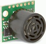
The sensors used are LV-MaxSonar-EZ1 Ultrasonic Range Finder MB1010.
The valid sensors output is a value between 6 and 254. This value is in inches and represents the distance to the obstacle, from the sensor. It is to be noted that if the obstacle is closer than 6 inches from the sensor it will not be detected.
The sensor provides output in three forms; As a pulse on the PW pin, where pulse width represents the distance to an obstacle; As an analog voltage on the AN pin; As a digital output on the TX pin, in RS-232 format. We have used the PW pin in this project to receive the input from the sensor.
It is to be noted that if two sensors which are placed so that their beams/detection areas overlap are ranging at the same time, they cause each other interference and hence incorrect values. Hence we trigger each sensor separately one by one so that at any time, only one sensor is ranging.
Hardware Interface
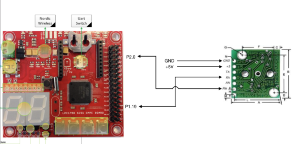
Pin connections for each sensor are as follows:
PW (Pin 2) - GPIO Pin configured as interrupt to receive input from sensor
RX (Pin 4) - GPIO Pin configured as output to trigger the sensor
VCC (Pin 6) - +5V
GND (Pin 7) - GND
Pin connections for the middle sensor are displayed.
Software Design
As described in the previous section, the sensors are triggered one by one to prevent corruption of data. In our implementation the sensors are triggered in the following order: middle, right, left and back. The back and left sensors are triggered together since they would not interfere with each other.
Every sensor needs a power-up time of 250 ms and some time to calibrate and take the first reading. After this period the sensor can provide a reading every 49 ms. In our implementation, all 4 sensor values are taken every 120 ms and put on the CAN bus. The format of the CAN message is shown in the following snippet taken from the DBC file. It can be observed that the sensor message has a high priority since it is critical to the operation of the car.
Implementation
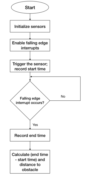
The following steps are followed to get a valid sensor reading.
1. Initialize the sensors - account for power up and calibration delay.
2. Enable falling edge interrupts and setup callback functions - this is to record the pulse width output of the sensor
3. Trigger each sensor and record the current time. This is the start time.
4. When falling edge interrupt occurs record the time. This is the end time.
5. Calculate pulse width using the start and end time. This pulse width would indicate the distance to the obstacle.
Technical Challenges
There were a few difficulties during implementation and testing of the sensors. Lessons learned include the following:
Challenge 1: Research different types of sensors, find out the strengths and weaknesses of each before making a decision.
Challenge 2: Ultrasonic sensors need to be slightly tilted upwards when mounted on the car to prevent them from accidentally detecting ground as an obstacle. This becomes especially necessary when testing on a slope/ramp.
Challenge 3: Ultrasonic sensors are very sensitive and care needs to be taken while soldering them. Accidental overheating can cause them to be destroyed.
Challenge 4: The ultrasonic sensors provide more range when +5V is used as supply rather than +3.3V.
Challenge 5: Testing both indoors and outdoors is necessary to check if the sensor readings are accurate in both conditions.
Motor Module
Motor module is one of the five controllers used in our self-driving car. Motor controller is responsible for driving the car forward and for steering the vehicle. The motor module has two motors viz.DC motor and Servo motor. DC motor makes the car move forward and reverse. Servo motor steers the car either left or right. Along with the two motors, we have the rpm speed sensor which is interfaced with our controller to control the speed of DC and move the car at the desired speed in Miles per Hour(MPH).
Hardware Design
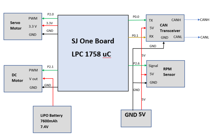
The Motor Module consists of 2 motors viz. DC motor and Servo motor controlled by an SJOne board by varying the PWM signals, which is nothing but the duty cycle. PWM stands for pulse-width modulation, a type of digital signal and can be used to control the motors. Along with two motors, we have interfaced the RPM sensor with the motor module micro-controller to get the wheel feedback and move our car at a constant speed even if the car is going uphill or downhill.
Hardware Interface
Servo Motor
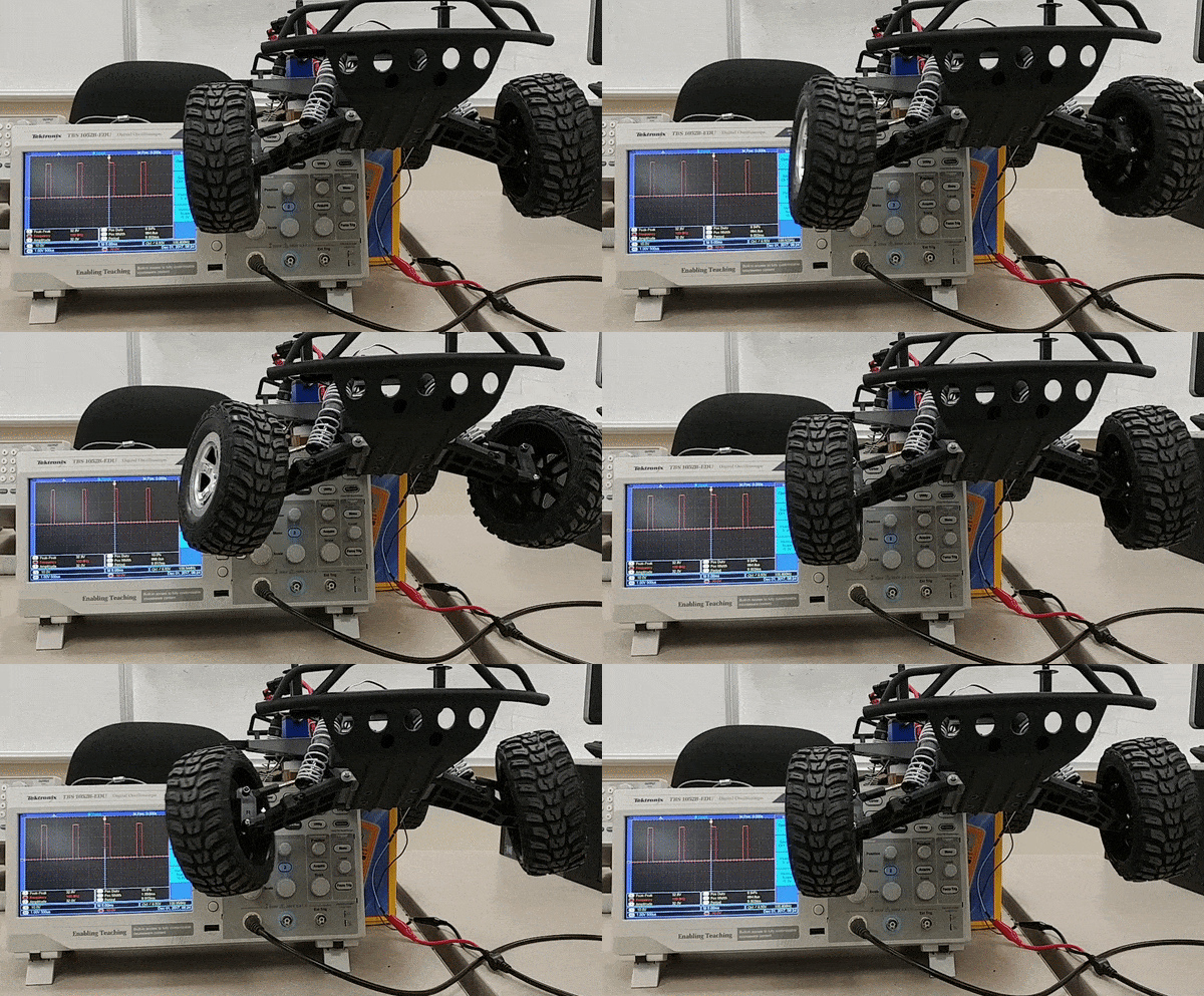
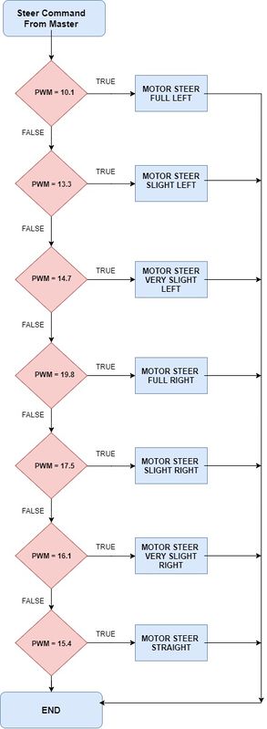
RC car came with a digital servo motor, requiring around 3-5V. The motor is directly controlled by giving a varying PWM signal from the SJOne board. Servo motor is used to convert an electrical signal into a linear motion. As per the PWM pulse received by the servo motor from SJOne board, it will rotate its shaft by a certain degree left or right. Below table gives the PWM values given to the motor for turning the car in the desired direction.
| No. | PWM | Direction |
|---|---|---|
| 1 | 10.1 | Full Left |
| 2 | 13.3 | Slight Left |
| 3 | 14.7 | Very Slight Left |
| 4 | 15.4 | Straight |
| 5 | 16.1 | Very Slight Right |
| 6 | 17.5 | Slight Right |
| 7 | 19.8 | Full Right |
DC Motor
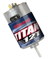
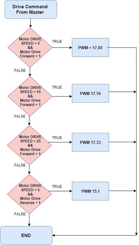
Like servo motor, the DC motor was also embedded in the RC car. The DC motor is used to convert an electrical signal into mechanical power. DC motor is controlled in the same manner as the servo motor i.e., by varying the PWM signal. The only difference here is that the PWM signal from the SJOne board is given to an Electronic Speed Controller or ESC. The ESC is used to generate three-phase electric power of low voltage in order to vary the speed of the DC motor. In case of no ESC, the DC motor will either not move or will start moving at full throttle. The RC car DC motor required 7.4V of power supply to work. The maximum speed that can be attained by this DC motor is 31mph.
Software Design
Testing & Technical Challenges
Following were the problems faced and their resolutions:
Problem 1: RPM sensor was not able to detect the magnet fixed on the wheel.
Solution 1: We had to stack together 3 magnets instead of one so that it was just millimeters away from the RPM sensor as well as its magnetic strength increased to be detected accurately by the RPM sensor.
Problem 2: Speed was not accurate with one magnet on the wheel.
Solution 2: Five magnets at an equidistant position from each other were used for better accuracy. More the magnets, better is the accuracy of speed calculation.
Problem 3: In spite of controlling speed using RPM sensor, the car was not in control while on a downhill.
Solution 3: After trying all possible solutions we could think of, we applied a brake momentarily at the start to reduce the sudden increase in PWM and then controlled the car based on the inclination. Also, made sure that if PWM value went below a certain range, then no brake was applied to the car.
Problem 4: The car did not go reverse all of a sudden even with the working code.
Solution 4: When checked with the transmitter/remote, still didn't work. It was found by reading the manual that ESC has 3 modes which can be set by long pressing the power button. And accidentally, ESC was changed to mode 2 where reverse wouldn't work. The car was set back to Mode 1.
Problem 5: Servo and DC motors didn't move even in open surroundings with no obstacles or MIA condition at one instance.
Solution 5: It was found that the Bluetooth start button was disabled from the Android application.
Geographical Controller
The geographical Controller is responsible for navigating the car in the direction of the destination selected by an android user. It uses a compass module for getting the heading angle with respect to the North and a GPS module which returns the current location of the car. After a particular destination has been chosen from the android app, the bridge module generates a number of checkpoints according to the shortest path algorithm. These are then sent to the geographical controller one by one. Using each of them, the bearing angle and the distance between the car and the checkpoint is calculated. Subsequently, the angle that the car should turn is determined and sent to the master module. On reaching the destination, the car is stopped.
Hardware Design
The Geographical controller makes use of the following two modules:
GPS
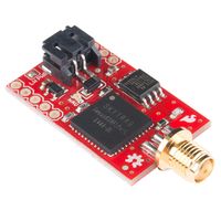
Venus638FLPx is used for detecting the location of the car. It returns the NMEA GPS string which needs to be parsed to get the latitude and longitude values from the module. It is a high performance, low cost, single chip GPS receiver that offers very low power consumption, high sensitivity, and best in the class signal acquisition and time-to-first-fix performance.
Features:
 20Hz update rate
-148dBm cold start sensitivity
-165dBm tracking sensitivity
29-second cold start TTFF
1-second hot start
2.5m accuracy
67mW full power navigation
Works directly with active or passive antenna
COMPASS
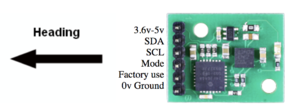
CMPS11 tilt-compensated compass module is employed for getting a heading angle value between 0-359. It requires a power supply of 3.6-5V. It can be interfaced via both serial(UART) and I2C. We have incorporated the I2C interface in which the 'mode' pin of the compass is left unconnected. It has a 28-byte array of registers and compass bearing can be read from 8-bit register 1.
Calibration of CMPS11 - We are using switch 1 and switch 2 of the SJOne board for entering and exiting the calibration mode respectively. When switch 1 is pressed, a 3-byte sequence of 0xF0, 0xF5 and 0xF6 is sent to the command register 0 and an led on the module starts blinking indicating the calibration mode. Compass is then slowly rotated in all 3 dimensions to get both negative and positive maximums. Only after the led completely extinguishes, switch 2 is pressed and a 0xF8 command is sent to exit the calibration mode. More accurate readings can be achieved by performing calibration meticulously.
Hardware Interface
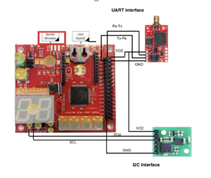
UART :
Pin connections for GPS are as follows:
VCC (Pin 1) - +5V
TX (Pin 2) - RX
RX (Pin 3) - TX
GND (Pin 4) - GND
I2C:
Pin connections for compass are as follows:
VCC (Pin 1) - +3.3V
SDA (Pin 2) - SDA
SCL (Pin 3) - SCL
GND (Pin 6) - GND
Software Design
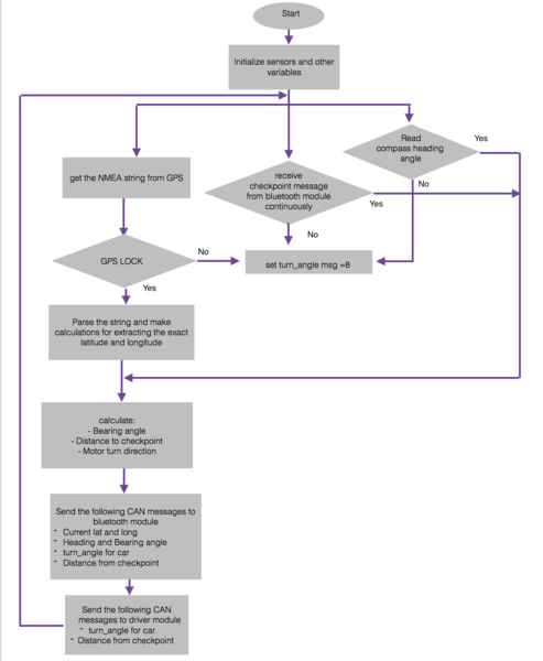
Flowchart
Algorithm
STEP 1: Read data from GPS sensor through UART and parse the string to get latitude and longitude of the current location.
STEP 2: Read satellite count from the GPS sensor to enable GPS lock.
STEP 2: Get heading angle from compass through I2C, the compass can be calibrated on pressing switch 3 and 4 at the same time and can be stopped on pressing switch 1.
STEP 3: Sending GPS heartbeat message on CAN bus to master, so that master knows that GPS module is connected.
STEP 3: Receiving destination location message on CAN bus from bridge controller.
STEP 4: Computing bearing angle from the current and destination locations obtained.
STEP 5: Sending the current location latitude and longitude obtained, to bridge controller on CAN bus.
STEP 6: Sending the bearing angle, heading angle and GPS lock enable in one message to the bridge controller through CAN bus.
STEP 7: Computing the distance between the current location and the destination location.
STEP 8: If the obtained distance is less than 5 meters then a message is sent to master as well as bridge controller, so that bridge controller can send the next checkpoint.
STEP 9: If all the checkpoints are done then that is the final destination, and bridge controller will not send any new location, so master should stop the car on receiving the car arrived message.
STEP 10: Finding the difference between heading angle and bearing angle, and realizing how much does the car should turn to navigate towards the destination.
STEP 11: Sending a car turn direction message to the master module, so that master module sends the message to the motor module to set a PWM frequency, depending on the message sent, to turn the car.
Implementation
Formulae used:
On obtaining the current latitude and longitude position, and destination latitude and longitude position should be determined from CAN message sent by bridge (Bluetooth) module. Bearing angle has to be computed from the obtained current location and destination location.
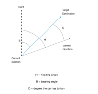
Bearing angle - Bearing angle is the angle between the direction towards the destination from the current location with respect to north. The bearing angle range is from 0 to 359.
Both bearing and heading angle’s should have the same range, can be from -180 to +180 or 0 to 360, we are using 0 to 360.
Degrees - We need to compute the angle that the car has to turn from its current direction towards the destination, from the obtained bearing angle(angle at which the car should go with respect to north to reach the destination) and heading angle (angle at which our car is going currently with respect to north).
Degree = Heading angle - Bearing angle
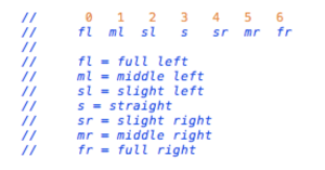
Depending on the degree, the car’s front wheel servo motors are to be turned accordingly. The turn direction messages to the master and their corresponding interpretations are as shown in the figure.
Distance Caluculation-
Testing & Technical Challenges
Problem 1: GPS usually takes a long time to get the fix.
Solution 1: The GPS module should be operated in hot start mode wherein an external battery(VBAT) of 3V is connected to it.
Problem 2: There was a significant delay(5-10 seconds, approximately) in the getting the latitude and longitude values while the car is moving.
Solution 2: The receive queue/buffer size of UART should be kept minimum.
Problem 3: The compass values were inaccurate.
Solution 3: The calibration needs to be done with a lot of patience. Also, it should be positioned as far away from magnets(GPS antenna and RPM sensors) as possible which can easily generate erroneous values from it.
Communication Bridge Controller & LCD
The purpose of Communication Bridge Controller is to establish communication between Andriod app and Car via the Bluetooth communication protocol. This ECU sends the updated checkpoints to Geo Controller at a particular instance when the car reaches at one checkpoint and sends the current location of the car to the phone so the tracking of the car on-road becomes easy. The Communication Bridge Controller also displays the Current location, Sensor readings, Car Speed on graphics LCD.
Hardware Design
This section highlights the hardware components used. The components used are SJOne board, Bluetooth, Gen4-uLCD-32PT (graphics LCD).
HC-05 Bluetoooth module
Used HC-05 Bluetooth modem to establish wireless communication between the car and the Android phone. This module is based on the Cambridge Silicon Radio BC417 2.4 GHz BlueTooth Radio chip. This is a complex chip which uses an external 8 Mbit flash memory It includes the Radio and Memory chips, 26 MHz crystal, antenna and RF matching network. The right section of the Bluetooth Board has connection pins for power and signals as well as a 5V to 3.3V Regulator, LED, and level shifting.
- HC-05 PinOut :
- EN: In case brought HIGH before power is applied, forces AT Command Setup Mode
- VCC: +3.3V Power
- GND: Ground
- TXD: Serial Transmit pin connected to RXD2 of SJOne board
- RXD: Serial Receive pin connected to TXD2 of SJOne board
- STATE: States if connected or not
- LED Blinking signals:
- if flashing RED fast: ready to pair
- if flashing RED slow: paired and connected
Gen4-uLCD graphics LCD
This project uses gen4 3.2” Picaso Integrated Display Module by 4D Systems. This LCD comes with resistive touch. It is powered by the well-known 4D Systems Picaso Graphics Processor, which offers a wide range of functionality and options for any Designer/Integrator. We have used Workshop4 IDE and its Visi-Genie development environment for interfacing the LCD with the controller.
Specifications and Features
- 4.0V to 5.5V range operation (single supply)
- Maximum current sunk/sourced by all ports- 200.0mA
- The Picaso processor features include 13 customisable GPIO, 2 Serial ports, and a Master I2C interface.
- The 3.2” Picaso Integrated Display Module features a TFT LCD Display, is capable of Touch Detection, microSD memory Storage, GPIO and Communications, along with multiple millisecond resolution timers, and Audio Generation.
- 14KB of Flash memory for User Application Code and Data
- 2 x Asynchronous hardware serial ports (COM0, COM1), TTL interface, with 300 to 600K baud.
- 1 x I2C interface (Master).
- 8 x 16-bit timers with 1-millisecond resolution.
- 13 x General Purpose I/O pins. Supports fast 8-bit parallel data transfer through Upper 8 bits.
- 30pin FPC connection, for all signals, power, communications, GPIO, and programming.
- On-board latch type micro-SD memory card connector for multimedia storage and data logging purposes.
- DOS compatible file access (FAT16 format) as well as low-level access to card memory.
Hardware Interface
The Communication Bridge Controller is the interface of communication between the user and the car. The ECU is interfaced with Bluetooth via UART and with graphics LCD via UART. The Communication Bridge Controller displays the messages on LCD. This section details the designs of the hardware components used for the communication and display. Android app routes the car.
Software Design and Implementation
Algorithm Design
- Step 1: Initialize the CAN controller, UART2 for Bluetooth communication, UART3 for graphics LCD, setting appropriate queue size for the UART and CAN communication.
- Step 2: For UART2, read the characters from the queue to decode the type of value. The string type is indicated by the starting character.
- Step 3: Convert the string to appropriate message, and store correctly. So after the conversion, the value can be either START_STOP, CHECKPOINTS_COUNT or LATITUDE_LONGITUDE.
- Step 4: For the simplicity, before reading the checkpoints the START_STOP bit is set to Zero and after reading all the checkpoints the START_STOP bit is set to One to Start the Car.
- Step 5: The car is running now to reach to the first checkpoint values. As the Car reaches in the suitable range of the location, the Communication Bridge ECU sends next checkpoint. Otherwise, it keeps on transmitting the checkpoint yet to reach.
- Step 6: Parallel with the wireless communication. The UART3 queue is getting the messages from CAN bus.
- Step 7: Calculate the checksum of the messages to display on LCD and Display important values like CURRENT_GPS_LOCATION, CAR_SPEED, GPS_BEARING, GPS_HEADING_ANGLE, DISTANCE_to_Destination, and CAR_TURN_ANGLE_Direction.
Testing & Technical Challenges
Problem 1:The first problem we had was to read the data from the queue. Some part of actual transmitted data from Android phones was not at all received in the queue.
Solution 1:We changed the timeout value and handled the newline character while reading data.
Problem 2:The second issue we had was that our START_STOP bit was dependent on "validate and store" function which if the START_STOP bit was not received, the default value
of zero was passed on the bus and that falsely stopped the car.
Solution 2:We transmitted the START_STOP bit only when we receive it, and not otherwise.
Master Module
The master module is the driver which is responsible for the smooth navigation of the car. It accepts all the inputs from sensors, the geo controller, the android app and makes a decision to drive the car according to this data received.
Hardware Design
The objective of the master module is to make the car reach the destination location via all the checkpoints given by the android app with the help of geo-controller. On its way to the destination, there may be obstacles in the path of the car which it should avoid at all times. The flow of the CAN messages is as shown below
Hardware Interface and Pin Connections
One SJ One board is used as a master controller. These boards have the following connections:
- CAN receiver and transmitter connections.
- Headlights and Taillights for the car.
- VCC and GND connections.
| Pin Number | Connection Details | Description |
|---|---|---|
| P 1.20 | Front LED | Headlights of the car |
| P 1.22 | Rear LED | Taillights of the car |
| P 0.1 | CAN TXPin | Connected to pin 7 of MCP2551 |
| P 0.0 | CAN RXPin | Connected to pin 6 of MCP2551 |
| GND | Connected to common ground | |
| 3V3 | Connected to incoming supply voltage | All the VCC are commong, coming from 5V battery supply. |
Software Design
The software flow of the master module is as shown in the following image. Let's get a brief idea of how it works,
1) In the beginning, all the CAN messages are received they are decoded according to the DBC file.
2) The android application provides the start and the stop commands for the car to get started or to be stopped when the car is stopped or running respectively.The car will not move until it receives the start signal from the android app. If it doesn't get the start signal from the app it will keep on reading CAN messages at 100Hz periodically.
3) First of all, after getting the start signal from the app it will check for the obstacles in the path where it is currently facing and if there are no obstacles in the path it will follow the GPS signals and move in the particular direction given by the GPS module.
4) Here we have given obstacle avoidance a higher priority than the GPS signal. If there are no obstacles then and only then it will follow GPS signals otherwise it will perform obstacle avoidance first.
Implementation
The software is made up of 3 main modules.
- Obstacle Avoidance
- Obstacle avoidance algorithm takes care of all the obstacles and moving direction of the car. Obstacle avoidance sends signals to move the car in a certain direction.
- Motor Commands Generator
- Indicators Controller
Overview of modules
- Obstacle Avoidance
- Obstacle avoidance algorithm is the essence if the driver module. It takes care of all the obstacles that come in between the path and avoids the car from colliding or hurting someone.
- Some properties of the obstacle avoidance algorithm,
- It uses a total of 3 sensors mounted at the precise angle on the car to detect obstacles that come in the front and 1 sensors for the rear of the car.
- Whenever all the front sensors senses an object in the middle it will keep on taking reverse with a left astern until the front is clear.
- When all the 4 sensors sense an object at the same time, the car will not move as there is no space for it to move.
- The priority for operation between all the modules is highest for obstacle avoidance.
- Obsatcle avoidance doesn't move the car at all when:
- There is a stop signal from the android app forcing the car to stop
- The destination is reached.
- Bluetooth, GPS, and Sensor modules are not on the CAN
- Some properties of the obstacle avoidance algorithm,
- Let's peek more into the working of obstacle avoidance algorithm,
- Obstacle avoidance algorithm is written based on the following state diagram. It keeps on checking the center sensor at the beginning. If the center sensor is sensing an object there is no way we can go further as the car may collide with an obstacle if it detects an obstacle. So, in this case, the car will check whether there is an object in the back or not if the back is also blocked the car will stop at the position. If the rear is not blocked it will take reverse until the front is unblocked. If the center direction is not blocked it will go straight in this case and keep on checking side sensors, if any one of the direction is blocked it will move in the opposite direction. If both the side sensors are blocked then the car will go into reverse condition as it does not have any front direction to go. If the rear is blocked during this operation the car will be stopped at that position, and if not it will take reverse until font direction is clear. If none of the direction is blocked it will always follow the GPS directions sent by GPS module.
- Motor Commands Generator
- This module is responsible for sending all the actions taken by obstacle avoidance to the motor.
- It sends following commands to the motor module at the execution of the obstacle avoidance algorithm.
- Angle at which the car should move
- Driving speed at which the motors should be driven
- Direction in which the car should go(Reverse or Forward)
- It frames this messages into a structure and sends to the motor to take control accordingly.
- Indicator Controller
- This module is responsible for controlling all the lights mounted on the car. The car has 2 head lights and 2 tail lights.
- All the indicators are updated in 100ms periodically
- Opearation of these lights are as following
Head Light Tail Light Car State On Off Going Forward Off On Stopped Off Blinking Going Reverse Blinking Blinking Reached The Destination
Android Application
A google map-based Android application was developed to provide the required information to our self-navigating car, Alpha to reach destination. The information includes the routing information between the source and the destination as well as a software-based command to start and to stop the car. This application also displays information regarding the current position and heading angle of Alpha.
Hardware Interface
Image of Interface between the android app and Bluetooth module is as shown. It has been explained in detail in the Bluetooth Module section.
Software Design
1. Bluetooth: Bluetooth allows to wirelessly exchange data with another Bluetooth device. Here, we are using Bluetooth to communicate our self-driving car with our Android application.
- 1.1. Enable Bluetooth: Bluetooth in the phone programmatically enabled using BluetoothAdapter. If Bluetooth in the phone is not enabled, then it can be enabled from the application.
- 1.2. Connect to Bluetooth on Car: A new Socket was created using UUID of Bluetooth device on Alpha. A connection request is sent by calling a connect method created on the socket. Here, "Connect" is the blocking call which will return if the connection request is accepted and the connection is established or an exception will be thrown. To establish an automatic connection between Alpha and the mobile device, a separate thread was created which will continuously check the connection and try to make a connection in case Bluetooth on the car is not connected. A connection indicator shows the current connection status.
- 1.3. Read from Alpha: Read the data from input-stream and convert it into accurate latitude, longitude, and heading angle. A separate thread is used to continuously read data and update it on the screen.
- 1.4. Write to Alpha: Write the data in the output stream so that it can be available to Alpha. In this application Start bit, Stop bit and the routing checkpoints are sent to move the car.
2. Routing Algorithm: Dijkstra Routing Algorithm is used to calcite shortest path algorithm between source and destination. Checkpoints are taken inside San Jose State University. Latitude and Longitude of each checkpoint are considered as a node of the directed graph. The routing path is stored as an array of checkpoints and sent to the car using Bluetooth. On the map, the routing is shown by blue line which connects to all checkpoints. All checkpoints between the cent location and the destination location are shown by violet colored markers, source location is shown by blue marker and destination is shown by red marker in routing path.
3. Start and Stop: Command to start the car and stop the car provided by the android application. Here, for both command, a single button is used as start and stop are alternative activity. Once the car is started by pressing on "GO" button on the application, the button on the app will convert in "STOP" button. A voice command indication is provided to Start and to stop.
Implementation
Algorithm:
PREREQ: All possible checkpoints should be previously saved in the app before the routing algorithm is run. This is a one-time activity.
1. Check Bluetooth Status
- a. If Bluetooth is not enabled
- Enable Bluetooth.
2. Fork a child thread for automatic connection to the car’s Bluetooth module.
3. Fork a child thread to read data from the car continuously from the Bluetooth connection.
4. Get the Destination from ‘On click’ method on the map.
5. On clicking on Go Button
- a. If Bluetooth connectivity lost
- Error: Car is not connected to Bluetooth
- b. Else If Destination is not selected
- Error: Destination is not selected
- c. Else
- I. Get current location latitude and longitude and save as source.
- II. Calculate routing path using Dijkstra routing algorithm.
- III. Send all checkpoints to the car using Bluetooth.
- IV. Send start message to the car via Bluetooth.
6. On clicking on Stop Button send stop message to the car using Bluetooth.
Algorithm For Automatic Connection Thread:
1. If Connection to car is available, go to sleep.
2. Else
- Delete Old socket.
- Create a new socket and send the connection request to connect.
- Go to sleep.
3. Repeat step 1 and 2 till app is destroyed.
Algorithm For Read data From Bluetooth Continuously:'
1. Read data from the Bluetooth buffer.
2. Convert data to Current Location and Compass Angle.
3. Display Current Location and Compass Angle on the Display Screen.
4. Repeat Step 1 to Step 4 till app is not destroyed.
Flowchart :
Testing & Technical Challenges
1. Automatic connection to Bluetooth: In case of Bluetooth connectivity lost while trying to reconnect using the same Socket was not connecting to Bluetooth again.
Solution: If connection lost between the Android app and Bluetooth a new Socket should create and try to connect using newly created socket. As, now old socket is not used delete old socket.
2. Routing Algorithm: There are many shortest path algorithm available which move from one checkpoint to another checkpoint in the map.(Logically all points on the map cannot be checkpoints.) In the application, current checkpoint and destination may not be from the checkpoint which is taken.
Solution: Make an algorithm to find the nearest checkpoint from the source towards the destination and connect source node to this checkpoint. In the same manner, Find nearest checkpoint from Destination towards the source and connect destination to this checkpoint. Calculate shortest path between these two checkpoint using Disktera's algorithm.
3. Adding Checkpoints: Checkpoint taken by the normal view of google map were not accurate.
Solution: All the checkpoints taken using satellite view of google map and accuracy confirmed by the reading from GPS used by the car.
Conclusion
We were able to successfully navigate our car to the destination location marked in our Android application by avoiding any obstacle that came in its path. This project gave us a real-world project experience. It helped us gain a working knowledge of CAN bus and communication, interfacing various components such as motors, GPS, Bluetooth and ultrasonic sensors along with some knowledge regarding pulse width modulation (PWM), UART, I2C. This course and project also gave us a deep understanding of FreeRTOS, Android, Unit testing and Git. Along the course of the project, we faced many hardware and software issues, especially while integrating a new module into the existing working solution. But, in spite of all the difficulties, we were able to achieve our goal with the help of proper understanding and teamwork. Working in a group of 10 and managing schedules and GIT branches to cover 5 different modules, it felt as if we were doing an internship. Overall, it was a great learning experience which molded us into better than what we were before we started.
Project Video
Project Source Code
Git Link - ALPHA
Acknowledgement
We would like to thank our professor, Preetpal Kang for designing such a course where learning was his guidance and consistent feedback. We would also like to thank the ISA team for their valuable inputs as per their own experience of the course when taken and their support and motivation at every phase of this project. There were some unsung, selfless classmates who helped us whenever necessary, whenever any immediate hardware was required or any other guidance needed in spite of being from the rival teams. We would like to thank each one of them who forgot their differences or considered the course and project as a competition to selflessly help us when in need.
References
[1] Preetpal Kang's lecture notes of CMPE 243, Computer Engineering, San Jose State University, Aug-Dec 2017.
[2] CAN Datasheet
[3] HC-05 Datasheet
[4] Ultrasonic sensor datasheet
[5] Routing Guide
[8] Venus638FLPx GPS datasheet
[9] CMPS11 datasheet
