Difference between revisions of "Embedded System Tutorial GPIO"
From Embedded Systems Learning Academy
(→Hardware) |
(→Hardware) |
||
| Line 59: | Line 59: | ||
==== Hardware ==== | ==== Hardware ==== | ||
| + | [[File:gpio_led_active_low.jpg|center|frame|Active-low LED circuit]] | ||
| + | [[File:gpio_led_active_high.jpg|center|frame|Active-high LED circuit]] | ||
| + | |||
==== Software ==== | ==== Software ==== | ||
<syntaxhighlight lang="c"> | <syntaxhighlight lang="c"> | ||
Revision as of 18:34, 20 October 2013
Contents
Objective
Interface your LPC17xx to a switch and an LED.
Although the interface may seem simple, you do need to consider hardware design and know some of the fundamental of electricity. There are a couple of goals for us :
- No hardware damage if faulty software is written.
- Circuit should prevent excess amount of current to avoid processor damage.
Required Background
- You should know how to bit-mask variables
- You should know how to wire-wrap
- You should know fundamentals of electricity and the famous V = IR equation.
Lecture
Hardware Registers
The hardware registers map to physical pins. If we want to attach our switch and the LED to our microcontroller's PORT0, then here are the relevant registers and their functionality :
| LPC_GPIO0->FIODIR | Direction of the port pins, 1 = output |
| LPC_GPIO0->FIOPIN |
Read : Sensed inputs of the port pins, 1 = HIGH Write : Control voltage level of the pin, 1 = 3.3v |
| LPC_GPIO0->FIOSET | Write only : Any bits written 1 are OR'd with FIOPIN |
| LPC_GPIO0->FIOCLR | Write only : Any bits written 1 are AND'd with FIOPIN |
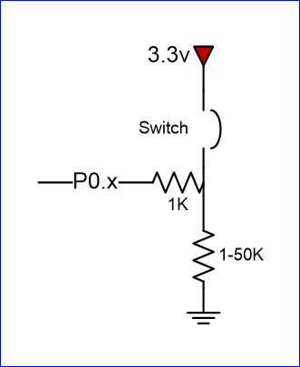
Switch
We will interface our switch to PORT0.2, or port zero's 3rd pin (counting from 0).
Hardware
Software
/* Make direction of PORT0.2 as input */
LPC_GPIO0->FIODIR &= ~(1 << 2);

/* Now, simply read the 32-bit FIOPIN registers, which corresponds to
 * 32 physical pins of PORT0.  We use AND logic to test if JUST the
 * pin number 2 is set
 */
if (LPC_GPIO0->FIOPIN & (1 << 2)) {
    // Switch is logical HIGH
}
else {
    // Switch is logical LOW
}
LED
We will interface our LED to PORT0.3, or port zero's 4th pin (counting from 0).
Hardware
File:Gpio led active low.jpg
Active-low LED circuit
File:Gpio led active high.jpg
Active-high LED circuit
Software
/* Make direction of PORT0.3 as OUTPUT */
LPC_GPIO0->FIODIR |= (1 << 3);

/* Setting bit 3 to 1 of IOPIN will turn ON LED
 * and resetting to 0 will turn OFF LED.
 */
LPC_GPIO0->FIOPIN |= (1 << 3);

/* Faster, better way to set bit 3 (no OR logic needed) */
LPC_GPIO0->FIOSET = (1 << 3);

/* Likewise, reset to 0 */
LPC_GPIO0->FIOCLR = (1 << 3);
Conclusion
At the end of this lab, you should be familiar with how a microcontroller's memory can access physical pins.
