Difference between revisions of "F17: Rolling Thunder"
Proj user2 (talk | contribs) (→Design & Implementation) |
Proj user2 (talk | contribs) (→Sensor Controller) |
||
| Line 427: | Line 427: | ||
Based on the beam angle of each sensor, they have been mounted to protect the front and rear of the car from hitting obstacles. | Based on the beam angle of each sensor, they have been mounted to protect the front and rear of the car from hitting obstacles. | ||
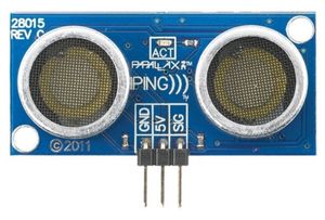
| − | [[File:CmpE243_F17_Rolling_Thunder_parallax.JPG|300px|thumb| | + | [[File:CmpE243_F17_Rolling_Thunder_parallax.JPG|300px|thumb|center|Parallax Ping Ultrasonic Sensor]] |
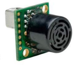
[[File:CmpE243_F17_Rolling_Thunder_maxbotix.JPG|500px|thumb|left|XL-Maxbotix-ez4 Ultrasonic Sensor]] | [[File:CmpE243_F17_Rolling_Thunder_maxbotix.JPG|500px|thumb|left|XL-Maxbotix-ez4 Ultrasonic Sensor]] | ||
| + | |||
| + | |||
| + | |||
| + | |||
| + | |||
| + | |||
| + | |||
=== Hardware Design === | === Hardware Design === | ||
Revision as of 19:09, 5 December 2017
Contents
- 1 Grading Criteria
- 2 Rolling Thunder
- 3 Abstract
- 4 Objectives & Introduction
- 5 Legend
- 6 Schedule
- 7 Parts List & Cost
- 8 Master Controller
- 9 Sensor Controller
- 10 Motor & I/O Controller
- 11 Geographical Controller
- 12 Android and Communication Bridge Controller
- 13 Conclusion
- 14 References
Grading Criteria
- How well is Software & Hardware Design described?
- How well can this report be used to reproduce this project?
- Code Quality
- Overall Report Quality:
- Software Block Diagrams
- Hardware Block Diagrams
- Schematic Quality
- Quality of technical challenges and solutions adopted.
Rolling Thunder
Abstract
This section should be a couple lines to describe what your project does.
Objectives & Introduction
Team Members & Responsibilities
- Master Controller
- Akil Khan
- Jerry John
- Geographical Controller
- Abhilash Tuse
- Vishal Shrivastava
- Communication Bridge + Android Application
- Akinfemi Akin-Aluko
- Johnny Nigh
- Motor and I/O Controller
- Saurabh Ravindra Badenkal
- Joshua Skow
- Sensor Controller
- Sona Bhasin
- Thrishna Palissery
- QA Team
- Akil Khan
- Saurabh Ravindra Badenkal
Legend
| Color | Component |
|---|---|
|
Blue |
Sensor Controller |
|
Green |
Motor/IO Controller |
|
Red |
Geographical Controller |
|
Orange |
Central Controller |
|
Indigo |
Communication Bridge + Android Application |
|
Brown |
QA |
Schedule
| Start Date | End Date | Task | Status | Date of Completion | |
|---|---|---|---|---|---|
| 1 | 09/20/2017 | 09/26/2017 |
|
Completed | 09/26/2017 |
| 2 | 09/27/2017 | 10/03/2017 |
|
Completed | 10/03/2017 |
| 3 | 10/04/2017 | 10/10/2017 |
|
Completed | 10/10/2017 |
| 10/10/2017 | Wiki Schedule | Completed | 10/10/2017 | ||
| 4 | 10/11/2017 | 10/17/2017 |
|
Completed | 10/17/2017 |
| 5 | 10/18/2017 | 10/24/2017 |
|
Completed | 10/24/2017 |
| 10/24/2017 | DBC File | Completed | 10/24/2017 | ||
| 10/24/2017 | DEMO: CAN communication between controllers | Completed | 10/24/2017 | ||
| 6 | 10/25/2017 | 11/28/2017 |
|
Completed | |
| 7 | 11/01/2017 | 11/07/2017 |
|
Completed | 11/07/2017 |
| 11/07/2017 | DEMO: Motors driven by wheel feedback and sensors, Basic obstacle avoidance
Final Wiki Schedule |
Completed | 11/07/2017 | ||
| 8 | 11/08/2017 | 11/14/2017 |
|
Completed | 11/14/2017 |
| 9 | 11/15/2017 | 11/21/2017 |
|
Completed | 11/21/2017 |
| 11/21/2017 | DEMO: GPS driving | Completed | 11/21/2017 | ||
| 10 | 11/22/2017 | 11/28/2017 |
|
In Progress | |
| 11 | 11/29/2017 | 12/19/2017 |
|
In Progress | |
| 12/20/2017 | DEMO: Final Project
SUBMISSION: Final Project Wiki |
Not started | |||
Parts List & Cost
| Item # | Description | Distributor | Qty | Cost |
|---|---|---|---|---|
| 1 | SJOne Board | Provided by Preet | 5 | $400 |
| 2 | RC Car - Traxxas 1/10 Slash 2WD | Amazon | 1 | $189.95 |
| 3 | Bluetooth Bee BLE 4.0 Module | ebay | 1 | $15 |
| 4 | GPS Module | Amazon | 1 | $28.99 |
| 5 | Compass (CMPS11) | Acroname | 1 | $45.95 |
| 6 | Traxxas 6520 RPM Sensor | Amazon | 1 | $10.82 |
| 7 | Traxxas 2991 LiPo Battery and Charger | Amazon | 1 | $199.95 |
| 8 | Breadboard Jumper Wires | Amazon | 1 | $6.99 |
| 9 | MIFFLIN Acrylic Plexiglass Clear Plastic Sheet | Amazon | 1 | $9.89 |
| 10 | Printed Circuit Board | Amazon | 1 | $16.83 |
| 11 | PCB Mounting Feet Set | Amazon | 1 | $11.99 |
| 12 | Traxxas 6538 Telemetry Trigger Magnet Holder | Amazon | 1 | $4.63 |
| 13 | MB1240 XL-MaxSonar EZ4 Ultrasonic Sensor | Amazon | 2 | $73.90 |
| 14 | Parallax Ping Ultrasonic Range Sensor | Amazon | 2 | $69.98 |
| 15 | CAN Transceiver | Microchip | 10 | Free |
| 16 | 4D systems 32u LCD | 4D Systems | 1 | $85.00 |
| 17 | Miscellaneous Items | 1 | $100.00 |
Master Controller
Design & Implementation
The master controller acts as the brainpower of the car and processes the data from the rest of the nodes to achieve smooth navigation of the car to its destination. As the master controller is the central controller of the entire system, it has to handle plenty of CAN messages.
Hardware Design
Discuss your hardware design here. Show detailed schematics, and the interface here.
Hardware Interface
In this section, you can describe how your hardware communicates, such as which BUSes used. You can discuss your driver implementation here, such that the Software Design section is isolated to talk about high level workings rather than inner working of your project.
Software Design
Show your software design. For example, if you are designing an MP3 Player, show the tasks that you are using, and what they are doing at a high level. Do not show the details of the code. For example, do not show exact code, but you may show psuedocode and fragments of code. Keep in mind that you are showing DESIGN of your software, not the inner workings of it.
Implementation
This section includes implementation, but again, not the details, just the high level. For example, you can list the steps it takes to communicate over a sensor, or the steps needed to write a page of memory onto SPI Flash. You can include sub-sections for each of your component implementation.
Testing & Technical Challenges
Describe the challenges of your project. What advise would you give yourself or someone else if your project can be started from scratch again? Make a smooth transition to testing section and described what it took to test your project.
Include sub-sections that list out a problem and solution, such as:
<Bug/issue name>
Discuss the issue and resolution.
Sensor Controller
Design & Implementation
The sensor controller oversees the functioning of ultrasonic sensors for the purpose of obstacle avoidance.
The sensor controller comprises of four ultrasonic sensors interfaced to an SJOne board. XL-Maxbotix-ez4 sensors are installed on the front and back of the car respectively and Parallax ping sensors are placed to guard the sides of the car from obstacles.
The XL-Maxbotix-ez4 sensor can detect obstacles up to 7.65 meters and works between a supply voltage range of 3.3 V to 5.5 V. The sensor operates at 42 KHz and is equipped with inbuilt acoustic and electrical noise filtering.
The Parallax ping sensor has a ranging distance of 3 meters working at a supply voltage of 5 V.
Based on the beam angle of each sensor, they have been mounted to protect the front and rear of the car from hitting obstacles.
Hardware Design
Discuss your hardware design here. Show detailed schematics, and the interface here.
Hardware Interface
In this section, you can describe how your hardware communicates, such as which BUSes used. You can discuss your driver implementation here, such that the Software Design section is isolated to talk about high level workings rather than inner working of your project.
Software Design
Show your software design. For example, if you are designing an MP3 Player, show the tasks that you are using, and what they are doing at a high level. Do not show the details of the code. For example, do not show exact code, but you may show psuedocode and fragments of code. Keep in mind that you are showing DESIGN of your software, not the inner workings of it.
Implementation
This section includes implementation, but again, not the details, just the high level. For example, you can list the steps it takes to communicate over a sensor, or the steps needed to write a page of memory onto SPI Flash. You can include sub-sections for each of your component implementation.
Testing & Technical Challenges
Describe the challenges of your project. What advise would you give yourself or someone else if your project can be started from scratch again? Make a smooth transition to testing section and described what it took to test your project.
Include sub-sections that list out a problem and solution, such as:
<Bug/issue name>
Discuss the issue and resolution.
Motor & I/O Controller
Design & Implementation
The Traxxas Slash is a 2 wheel drive car makes use of two motors:
Titan 12-turn 550 modified motor:

This motor is responsible for driving the rear wheels. This motor takes in a 100Hz duty cycle - 10-15% drives the motor in reverse, 15-20% drives the motor forward.
Traxxas 2075 Waterproof Servo motor:
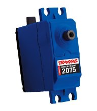
This motor is responsible for turning the two front wheels left and right. The servo operates on the same duty cycle as the driver motor; 10-15% duty cycle turns the wheels left, 15-20% duty cycle turns the wheels right.
Hardware Design
The schematic of the motor controller is:
The Traxxas Slash receiver box contains 3 pin connectors for signal, input voltage (VCC) and ground. There are 4 3 pin connectors that come on the Traxxas Slash receiver - 3 of which are used for the car (Servo motor, Driver motor, and RPM sensor). The VCC of each connector is shorted together, and tied to the car battery. The grounds are all shorted as well and connected to the PCB of everything on the car.
The RPM sensor is connected physically to the gearbox, with a small magnet attached to the largest gear. There is a small hall sensor mounted next to this large gear, and every time the gear makes a revolution the hall sensor provides a high pulse indicating the a rotation. The RPM sensor signal is tied to a GPIO on the SJOne board.
Hardware Interface
The motor controller contains the following interfaces to the SJOne:
- PWM to the Driver motor
- PWM to the Servo motor
- GPIO to the RPM sensor
- GPIO to the ADC for battery voltage monitoring
Software Design
The motor is abstracted as a C++ class. The motor class is able to set the Driver motor and the Servo motor.
The motor class is also responsible for taking in a desired speed, and making sure the car is driving at that speed. The motor class interprets the RPM sensor output, determines the current car speed compared to the desired car speed, and drives the motor to make the current car speed as close to the desired speed as possible.
The motor used a PID (proportional, integral, derivative) based control algorithm to keep the actual motor speed as close as possible to the desired speed. The tuning was done with the car mounted on a platform. The PID was tuned with the following method:
1. Select a proportional coefficient and change it until the motor feedback has a minimal oscillation. 2. Increase the derivative coefficient until there are no more oscillations. 3. Increase the integral coefficient until the speed increases fast enough and there is no oscillations.
Implementation
This section includes implementation, but again, not the details, just the high level. For example, you can list the steps it takes to communicate over a sensor, or the steps needed to write a page of memory onto SPI Flash. You can include sub-sections for each of your component implementation.
Testing & Technical Challenges
Describe the challenges of your project. What advise would you give yourself or someone else if your project can be started from scratch again? Make a smooth transition to testing section and described what it took to test your project.
Include sub-sections that list out a problem and solution, such as:
<Bug/issue name>
Problems faced by motor:
- Measure the motor speed accurately (measure for # of pulses vs. time between pulses)
- How to know when the car is stopped
- How to make the car be the desired speed (steps vs PID)
- Tuning the PID loop
Geographical Controller
Group Members
- Abhilash Tuse
- Vishal Shrivastava
Design & Implementation
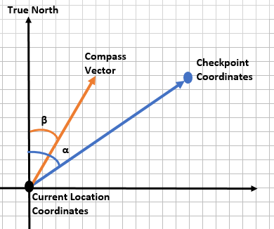
The Geographical Controller is in place for navigation purpose. It has two essential parts, namely GPS and compass. It provides direction to the car, by calculating the heading angle and the distance between the coordinates, based on GPS and compass readings. To calculate heading angle, we need compass bearing angle and angle between the line joining the two coordinates and the true north (bearing angle for GPS).
GPS Bearing angle calculation
With the reference to the figure, the bearing angle for GPS is the angle between the line joining the two coordinates and the true north. To calculate it graphically, draw a vector pointing towards the destination coordinates from the start point coordinate and measure the angle between the vector and the true north. Use the below formula to calculate the angle mathematically.
 Bearing angle(α) = atan2(sin Δλ ⋅ cos φ2 , cos φ1 ⋅ sin φ2 − sin φ1 ⋅ cos φ2 ⋅ cos Δλ)
 where,
       φ1 = Latitude of 1st Coordinate
       φ2 = Latitude of 2nd Coordinate
       λ1 = Longitude of 1st Coordinate
       λ2 = Longitude of 2nd Coordinate
       Δλ = λ2 - λ1
Heading angle calculation
The heading angle is the angle between the compass vector and the vector drawn for calculating GPS bearing angle.
 Heading angle(γ) = α – β
 where,
       α = Angle between the line joining the two coordinates and the true north
       β = Angle between compass vector and the true north (Compass bearing angle)
If heading angle is positive the car turns right or else turns left.
Distance between the two coordinates calculation
The distance between the two coordinates can be calculated using the Haversine formula.
 a = sin²(Δφ/2) + cos φ1 ⋅ cos φ2 ⋅ sin²(Δλ/2)
 c = 2 ⋅ atan2(√a, √(1−a))
 d = R ⋅ c
 where,
       φ1 = Latitude of 1st Coordinate
       φ2 = Latitude of 2nd Coordinate
       λ1 = Longitude of 1st Coordinate
       λ2 = Longitude of 2nd Coordinate
       Δφ = φ2 - φ1
       Δλ = λ2 - λ1
       d  = distance between the two coordinates
       R  = earth’s radius (mean radius = 6,371km)
 Note: All the angles should be in radians.
Hardware Design
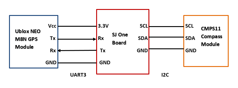
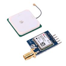
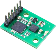
The diagram below shows the h/w interfacing of SJ1 board with GPS module and Compass module. The GPS module and the Compass module is communicating over UART3 and I2C respectively with SJ One board.
Pin mapping of GPS module with SJ ONE board:
| GPS Module Pins | SJ ONE Board Pins |
|---|---|
| Vin | 3.3v |
| GND | GND |
| TX | RXD3 |
| RX | TXD3 |
Pin mapping of Compass module with SJ ONE board:
| Compass Module Pins | SJ ONE Board Pins |
|---|---|
| GND | GND |
| SDA | SDA |
| SCL | SCL |
Compass module requires an external power supply of 5V.
GPS Module
Compass Module
Hardware Interface
In this section, you can describe how your hardware communicates, such as which BUSes used. You can discuss your driver implementation here, such that the Software Design section is isolated to talk about high level workings rather than inner working of your project.
Software Design
Show your software design. For example, if you are designing an MP3 Player, show the tasks that you are using, and what they are doing at a high level. Do not show the details of the code. For example, do not show exact code, but you may show psuedocode and fragments of code. Keep in mind that you are showing DESIGN of your software, not the inner workings of it.
Implementation
This section includes implementation, but again, not the details, just the high level. For example, you can list the steps it takes to communicate over a sensor, or the steps needed to write a page of memory onto SPI Flash. You can include sub-sections for each of your component implementation.
Testing & Technical Challenges
Describe the challenges of your project. What advise would you give yourself or someone else if your project can be started from scratch again? Make a smooth transition to testing section and described what it took to test your project.
Include sub-sections that list out a problem and solution, such as:
<Bug/issue name>
Discuss the issue and resolution.
Android and Communication Bridge Controller
Design & Implementation
The design section can go over your hardware and software design. Organize this section using sub-sections that go over your design and implementation.
Hardware Design
Discuss your hardware design here. Show detailed schematics, and the interface here.
Hardware Interface
In this section, you can describe how your hardware communicates, such as which BUSes used. You can discuss your driver implementation here, such that the Software Design section is isolated to talk about high level workings rather than inner working of your project.
Software Design
Show your software design. For example, if you are designing an MP3 Player, show the tasks that you are using, and what they are doing at a high level. Do not show the details of the code. For example, do not show exact code, but you may show psuedocode and fragments of code. Keep in mind that you are showing DESIGN of your software, not the inner workings of it.
Implementation
This section includes implementation, but again, not the details, just the high level. For example, you can list the steps it takes to communicate over a sensor, or the steps needed to write a page of memory onto SPI Flash. You can include sub-sections for each of your component implementation.
Testing & Technical Challenges
Describe the challenges of your project. What advise would you give yourself or someone else if your project can be started from scratch again? Make a smooth transition to testing section and described what it took to test your project.
Include sub-sections that list out a problem and solution, such as:
<Bug/issue name>
Discuss the issue and resolution.
Conclusion
Conclude your project here. You can recap your testing and problems. You should address the "so what" part here to indicate what you ultimately learnt from this project. How has this project increased your knowledge?
Project Video
Upload a video of your project and post the link here.
Project Source Code
References
Acknowledgement
Any acknowledgement that you may wish to provide can be included here.
References Used
List any references used in project.
Appendix
You can list the references you used.
