Difference between revisions of "S13: 2D Plotter"
Matthias s13 (talk | contribs) (→Objectives & Introduction) |
(→Project Source Code) |
||
| (85 intermediate revisions by one other user not shown) | |||
| Line 1: | Line 1: | ||
| − | |||
| − | |||
| − | |||
| − | |||
| − | |||
| − | |||
| − | |||
| − | |||
| − | |||
| − | |||
| − | |||
| − | |||
| − | <h2 style=" | + | <h2 style=" font-family:arial; font-size:36px; text-align:center; color:grey;"> |
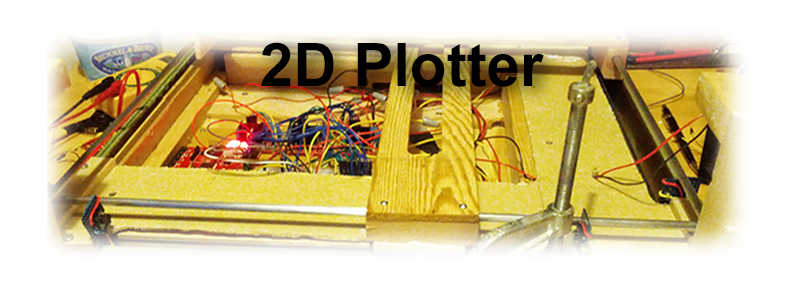
| − | [[File: | + | [[File:CmpE146_S13_T1_banner.png]]</h2> |
== Abstract == | == Abstract == | ||
| − | The | + | The following text describes the design, programming, and testing of a simple plotter. A plotter is a computer output device similar to a printer that is designed to print a design based on vectors.<br /> |
| − | + | ||
| − | + | This plotter was developed as the final project for the Embedded Systems Class (CmpE146) at San Jose State University, California. It consists of a wooden chassis, three stepper motors to position the print head and move the pen, and an ARM-based controller board running FreeRTOS.<br /> | |
| − | + | ||
| + | To test the plotter, a simple text will be printed once the device has been completed.<br /> | ||
== Objectives & Introduction == | == Objectives & Introduction == | ||
| − | |||
| − | The | + | The purpose of this project is to design a simple plotter. This plotter could then be modified to serve as a CNC router, a laser cutter, or any other vector-based 2D output device. In addition, the design of the plotter is intended as a preliminary step towards the design of a 3D printer. The experience from the design of the plotter will allow us to asses which of our current ideas can be realized with the hardware and software options available to use at the current time.<br /><br /> |
| + | |||
| + | One main objective of the design is to reuse as many existing components as possible. For example, belts, gears, and motors from old inkjet printers have been collected to be used in this design.<br /><br /> | ||
| − | + | '''As far as the operation of the plotter is concerned, the objectives of this project are:'''<br /> | |
| − | |||
| − | |||
| − | |||
| + | * Use the ARM-based SJSU-ONE board to control all necessary hardware through GPIOs.<br /> | ||
| + | * Design a wooden enclosure for the hardware. <br /> | ||
| + | * Create a program that allows control of the hardware to create some useful output. <br /> | ||
| − | + | == Team Members & Responsibilities == | |
| − | * Matthias | + | * '''Matthias''' |
** Hardware Development | ** Hardware Development | ||
| − | * | + | * '''William''' |
** Driver Development | ** Driver Development | ||
| − | * | + | * '''Sergey''' |
| − | ** | + | ** Wiki and Documentation |
== Schedule == | == Schedule == | ||
| Line 114: | Line 104: | ||
<td> | <td> | ||
* Done | * Done | ||
| − | * | + | * Done |
| − | * | + | * Done |
| − | * | + | * Done |
</td> | </td> | ||
</tr> | </tr> | ||
| Line 130: | Line 120: | ||
</td> | </td> | ||
<td> | <td> | ||
| − | * | + | * Done |
| − | * | + | * Done |
</td> | </td> | ||
</tr> | </tr> | ||
| Line 143: | Line 133: | ||
|- | |- | ||
! Parts | ! Parts | ||
| + | ! Quantity | ||
! Cost | ! Cost | ||
|- | |- | ||
| 2012 SJ One Board | | 2012 SJ One Board | ||
| − | | $65 | + | | 1 |
| + | | $65.00 | ||
|- | |- | ||
| − | | | + | | Nema 17 Stepper Motors |
| + | | 3 | ||
| $33.20 | | $33.20 | ||
|- | |- | ||
| − | | | + | | Stepper Motor Controller |
| − | | $ | + | | 3 |
| + | | $12.39 | ||
|- | |- | ||
| − | | | + | | Steel Rods (8mm diameter), 4 feet |
| − | | $ | + | | 4 |
| + | | $14.76 | ||
|- | |- | ||
| Power supply | | Power supply | ||
| − | | $10 | + | | 1 |
| + | | $10.00 | ||
|- | |- | ||
| − | | New wood ( | + | | New wood (5mm thick) |
| + | | 6 | ||
| $8.94 | | $8.94 | ||
|- | |- | ||
| Breadboard | | Breadboard | ||
| − | | $7 | + | | 1 |
| + | | $7.00 | ||
| + | |- | ||
| + | | Push Buttons | ||
| + | | 4 | ||
| + | | $3.96 | ||
| + | |- | ||
| + | | 47K Resistor | ||
| + | | 4 | ||
| + | | $0.50 | ||
|- | |- | ||
| − | | | + | | Sharpie |
| − | | $ | + | | 1 |
| + | | $1.99 | ||
|- | |- | ||
| 4 to 16 decoder | | 4 to 16 decoder | ||
| − | | $3 | + | | 1 |
| + | | $3.00 | ||
|- | |- | ||
| Old wood | | Old wood | ||
| − | | $0 | + | | Various |
| + | | $0.00 | ||
|- | |- | ||
| Screws | | Screws | ||
| − | | $0 | + | | Various |
| + | | $0.00 | ||
|- | |- | ||
| − | | Old printer gears | + | | Old printer gears (various sized) |
| − | | $0 | + | | 6 |
| + | | $0.00 | ||
|- | |- | ||
| Old printer belts | | Old printer belts | ||
| − | | $0 | + | | 3 |
| + | | $0.00 | ||
|- | |- | ||
| Wires | | Wires | ||
| − | | $0 | + | | Various |
| + | | $0.00 | ||
|- | |- | ||
| − | | Glue | + | | Gorilla Glue |
| − | | $ | + | | 1 Tube |
| + | | $4.99 | ||
|- | |- | ||
| + | ! | ||
! Total: | ! Total: | ||
| − | ! $ | + | ! $166.53 |
|} | |} | ||
== Design & Implementation == | == Design & Implementation == | ||
| − | |||
=== Hardware Design === | === Hardware Design === | ||
| − | + | ||
| + | In designing the plotter, three main components need to be considered. These are the mechanical design, which consists of: | ||
| + | |||
| + | * The chassis, motors and timing belts, and the rails to position the print head on a two-dimensional grid | ||
| + | * The electronics to control the stepper motors and any limit switches used to ensure proper position | ||
| + | * The software to communicate with the hardware in order to produce the expected output.<br /> | ||
| + | |||
| + | ==== Case and Mechnical Components ==== | ||
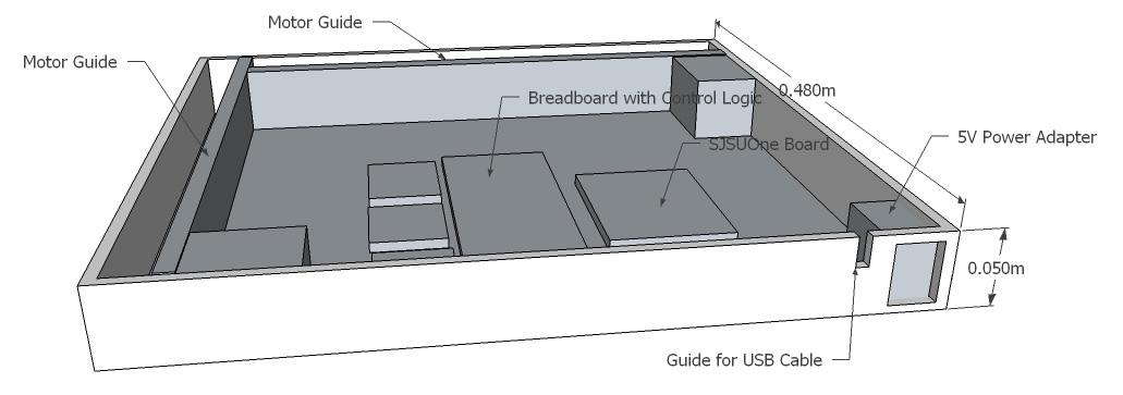
| + | The plotter base consists of a 48 cm x 48 cm x4.5 cm enclosure (see Illustration 1) that holds the motors, the mechanical components to move the timing belts, and the electronic components.<br /> | ||
| + | <center> | ||
| + | [[File:CMPE146 s13 T1 Chassis.jpg]] | ||
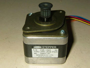
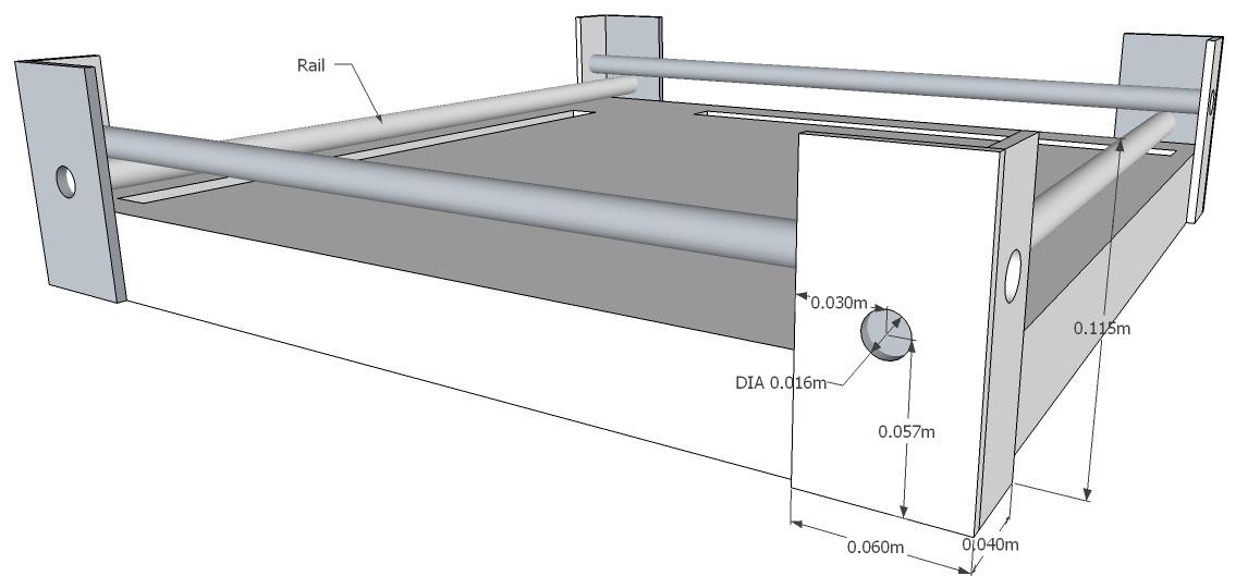
| + | </center> | ||
| + | <div style="text-align: center;">'''Illustration 1:''' The Plotter Enclosure </div><br /> | ||
| + | |||
| + | Each of the two motor guides consist of one NEMA 17 stepper motor (see Illustration 2), a large gear to hold the timing belt, and a smaller gear to position the timing belt near the top of the motor guide. To mount the motor, a large hole for the gear shaft and two small screw holes to mound the motor were drilled on one side (see Illustration 3). The gears can be attached using screws. For this particular plotter, special pins to hold plastic hears were glued into small holes. These pins were salvaged form an old inkjet printer.<br /> | ||
| + | |||
| + | [[File:CMPE146_s13_T1_NEMA17.jpg|center|frame]] | ||
| + | <div style="text-align: center;">'''Illustration 2:''' NEMA17 Stepper Motor</div><br /> | ||
| + | |||
| + | [[File:CMPE146 s13 T1 Rail.jpg|center]] | ||
| + | <div style="text-align: center;">'''Illustration 3:''' Motor Guide </div><br /> | ||
| + | |||
| + | The rails to move the print head are attached to columns on the side of the printer (see Illustration 4). These rails were cut to fit from 8 mm metal bars and should be placed in parallel on opposite sides of the printer for each of the two directions. A thin opening is cut in the base where the timing belt is located. This will be the point where the two sliders are mounted to the timing belts.<br /> | ||
| + | |||
| + | [[File:CMPE146_s13_T1_BaseWithRails.jpg|center]] | ||
| + | <div style="text-align: center;">'''Illustration 4:''' Base with Rails </div><br /> | ||
| + | |||
| + | The slider is currently comprised of a block of wood with a fitting guide hole. Caution should be taken that the guide block fits snugly yet can move without too much friction. Ideally, these wooden blocks would be replaced with linear ball bearings. If the rails are not completely parallel, it might be necessary to cut the guide slider on one side so that it rests loosely on the rail. This involves cutting the bottom of the slider with a saw so that the hole is turned into a half-circular groove. Illustration 5 shows an actual picture of the guide block attached to the timing belt.<br /> | ||
| + | |||
| + | |||
| + | [[File:CMPE146_s13_T1_AttachingSliderToBelt.jpg|center|frame]] | ||
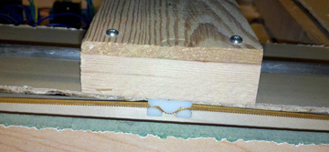
| + | <div style="text-align: center;">'''Illustration 5:''' Attaching Slider to Timing Belt</div><br /> | ||
| + | |||
| + | Two thin wooden boards with a cut-out center are mounted crisscross on the sliders. The pen mounting mechanism is then positioned in the intersection of the two boards (see Illustration 6). It should move smoothly as the sliders are positioned in the x and the y directions. For this plotter, an empty wire-wrapping cable spool was cut in half and placed in the opening. To re-attach the two halves, a 3” strip of thin cardboard was rolled up and pushed inside the spool, holding the two pieces together. <br /> | ||
| + | |||
| + | [[File:CMPE146_s13_T1_CompletedBase.jpg|center]] | ||
| + | <div style="text-align: center;">'''Illustration 6:''' Base with Rails and Attached Sliders</div><br /> | ||
| + | |||
| + | The print head was initially designed using a large electromagnet mounted on top of a round tube. A sharpie with a metal washer glued to the top was placed underneath the magnet, and a relays circuit was designed to activate the relay. The circuit worked on the bread board, but the GPIO pin did not provide sufficient current to activate the relay, so after some failed attempts to fix the circuit, a new approach using a stepper motor was devised (see Illustrations 7). The new way was actually easier to use and more reliable.<br /> | ||
| + | |||
| + | [[File:CMPE146_s13_T1_PenCloseUp.jpg|center]] | ||
| + | <div style="text-align: center;">'''Illustration 7:''' The Print Head</div><br /> | ||
| + | |||
| + | The print head is secured in the intersection of the two rails using a small cable spool that was cut in half. An empty glue stick tube (any tube with the correct diameter will work as long as it can be cut easily) that is positioned in the middle of the spool holds the top and bottom part together. By removing the bottom, the print head assembly can be removed easily. A thin slit is cut in the side of the tube so that the rotating shaft of a motor mounted next to it will be positioned in front of the opening. A rubber band is then wound along the shaft so that it will secure a pen in place inside the tube. Moving the stepper motor clockwise or counter-clockwise will now raise or lower the pen easily. | ||
| + | |||
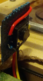
| + | For calibration and feedback, four limit switches were added to at each end of the the two rails. The buttons were designed using a pull-down resistor (see Illustration 8), and they were wired to four GPIO pins. By reading the button status, the driver can determine if it has reached the end of a rail. The calibration information could also be used to calculate the step size by counting the number of steps from one button event to the next, and dividing the total length of the rail by the number of steps. A closeup of one limit button is shown in Image 9.<br /> | ||
| + | |||
| + | [[File:CMPE146_s13_T1_LimitButtonWiring.jpg|center]] | ||
| + | <div style="text-align: center;">'''Illustration 8:''' Wiring the Limit Button</div><br /> | ||
| + | |||
| + | [[File:CMPE146_s13_T1_LimitButtons.jpg|center]] | ||
| + | <div style="text-align: center;">'''Illustration 9:''' A Limit Button</div><br /> | ||
=== Hardware Interface === | === Hardware Interface === | ||
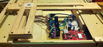
| − | + | The stepper motor are controlled using two STMicroelectronics L298N Full-bridge motor drivers, which are attached to the SJSU-One ARM-based controller board (see Illustration 10).<br /> | |
| + | |||
| + | [[File:CMPE146_s13_T1_MotorLayout.jpg|center|frame]] | ||
| + | <div style="text-align: center;">'''Illustration 10:''' Inside View of the Plotter </div><br /> | ||
| + | |||
| + | The L298N can control a 4-wire bipolar stepper motor using a 4-bit binary input. It is possible to control up to four motors with a 4 of 16 decoder such as a 74LS154. We are currently using a 4-to-16 decoder to control the three motors used for the plotter.<br /> | ||
| + | |||
| + | ==== Electronic Design ==== | ||
| + | |||
| + | The system diagram in Illustration 11 shows the key components of the electrical system designed to control the prtinter.<br /> | ||
| + | |||
| + | [[File:CmpE146_S13_T1_SystemDiagram.jpg|center|frame]] | ||
| + | <div style="text-align: center;">'''Illustration 11:''' System Diagram </div><br /> | ||
| + | |||
| + | ''Power Supply'' | ||
| + | |||
| + | The 5V power supply is used to power the stepper motor controllers and the microcontroller. However, during development, the system board is powered via a USB cable since the same cable is used for programming the hardware.<br /> | ||
| + | |||
| + | ''SJSUOne Board'' | ||
| + | |||
| + | The SJSUOne board is an ARM-based microcontroller running FreeRTOS. It is used to communicate with the external hardware via GPIO pins.<br /> | ||
| + | |||
| + | ''Limit Buttons'' | ||
| + | |||
| + | The limit button (Btn_1 though Btn_4) are used to provide feedback about the horizontal and vertical position of the print head. THe button is triggered when any of the two sliders has reached the end of a rail.<br /> | ||
| + | |||
| + | ''4-to-16 Decoder (74153)'' | ||
| + | |||
| + | The decoder is used to activate a particular coil in the stepper motor. A 4-to-16 decoder can control up to four motors, but it can only run one motor at a time. Each motor required 4 consecutive output pins on the decoder.<br /> | ||
| + | |||
| + | ''L298-Based Stepper Motor Controller'' | ||
| + | |||
| + | Each of the three stepper motor controllers is wired to the decoder and to one of the stepper motors. It activates a particular coil in the motor that is attached to it based on the input from the decoder. For example, 0010 activates coil 3 in motor one.<br /> | ||
| + | |||
| + | ''Motor'' | ||
| + | |||
| + | The motors used in this system are standard NEMA 17 type stepper motors common in plotters and 3D printers. This bi-polar stepper motor has 4 wires to control four coils in the motor.<br /> | ||
| + | |||
| + | ==== Limit Switches ==== | ||
| + | |||
| + | Each limit switch is hooked up to one GPIO input pin. In our implementation, the following pins were used:<br /> | ||
| + | |||
| + | * Button 1: P1:26 | ||
| + | * Button 2: p1:27 | ||
| + | * Button 3: p0:4 | ||
| + | * Button 4: p0:5 | ||
| + | |||
| + | ==== Stepper Motor Controller ==== | ||
| + | |||
| + | While there is a wide variety of stepper motor controllers, the one we used is shown in Illustration 12. It uses an L298 chip for motor control, and it is powered by a 5V power supply. While the controller can handle higher voltages, 5V provides sufficient power, and the chip quickly overheats when using 12V. The four input controls on the stepper motor controller are connected to the outputs for each pin as shown below:<br /> | ||
| + | |||
| + | {| class="wikitable" | ||
| + | |- | ||
| + | ! Decoder Input | ||
| + | ! DEcoder Output Pin | ||
| + | ! Motor # | ||
| + | ! Stepper Controller Input Pin | ||
| + | |- | ||
| + | | 0000 | ||
| + | | 0 | ||
| + | | 1 (Horizontal Control) | ||
| + | | 1 | ||
| + | |- | ||
| + | | 0001 | ||
| + | | 1 | ||
| + | | 1 (Horizontal Control) | ||
| + | | 2 | ||
| + | |- | ||
| + | | 0010 | ||
| + | | 2 | ||
| + | | 1 (Horizontal Control) | ||
| + | | 3 | ||
| + | |- | ||
| + | | 0011 | ||
| + | | 3 | ||
| + | | 1 (Horizontal Control) | ||
| + | | 4 | ||
| + | |- | ||
| + | | 0100 | ||
| + | | 4 | ||
| + | | 2 (Vertical Control) | ||
| + | | 1 | ||
| + | |- | ||
| + | | 0101 | ||
| + | | 5 | ||
| + | | 2 (Vertical Control) | ||
| + | | 2 | ||
| + | |- | ||
| + | | 0110 | ||
| + | | 6 | ||
| + | | 2 (Vertical Control) | ||
| + | | 3 | ||
| + | |- | ||
| + | | 0111 | ||
| + | | 7 | ||
| + | | 2 (Vertical Control) | ||
| + | | 4 | ||
| + | |- | ||
| + | | 1000 | ||
| + | | 8 | ||
| + | | 3 (Pen Control) | ||
| + | | 1 | ||
| + | |- | ||
| + | | 1001 | ||
| + | | 9 | ||
| + | | 3 (Pen Control) | ||
| + | | 2 | ||
| + | |- | ||
| + | | 1011 | ||
| + | | 10 | ||
| + | | 3 (Pen Control) | ||
| + | | 3 | ||
| + | |- | ||
| + | | 1011 | ||
| + | | 11 | ||
| + | | 3 (Pen Control) | ||
| + | | 4 | ||
| + | |- | ||
| + | |} | ||
| + | |||
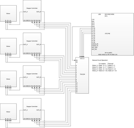
| + | The schematic for this motor setup is shown in Illustration 13. <br /> | ||
| + | |||
| + | [[File:CmpE146_S13_T1_StepperMotorController.jpg|center|frame]] | ||
| + | <div style="text-align: center;">'''Illustration 12:''' Stepper Motor Controller </div><br /> | ||
| + | |||
| + | [[File:CMPE146_s13_T1_MotorControl.jpg|center|frame]] | ||
| + | <div style="text-align: center;">'''Illustration 11:''' Stepper Motor Control </div><br /> | ||
| + | |||
| + | ==== Stepper Motor Wiring ==== | ||
| + | |||
| + | While NEMA 17 is a standard form factor for stepper motors, not all NEMA 17 motors are wired identical. Our motors were wired as follows:<br /> | ||
| + | |||
| + | * Ground: Orange (connected to output A), Blue (connected to output B) | ||
| + | * Coils 1,3: Red (connected to output A) | ||
| + | * Coils 2,4: Yellow (connected to output B) | ||
| + | |||
| + | To determine which wires are paired, simply test the resistance through a pair of wires.<br /> | ||
=== Software Design === | === Software Design === | ||
| − | + | ||
| + | The current printer driver consists of the printerTask(), which is scheduled in the main function. The function of this task is to listen to a button event to run a test program. All the task-related functions are kept in a dedicated printer library, which consists of the <i>printer.hpp</i> header file and the code library <i>printer.cpp</i>.<br /> | ||
| + | |||
| + | '''printer.hpp''' | ||
| + | <pre> | ||
| + | bool motor_init(); | ||
| + | bool motor_control(int motor, bool direction, int duration, int speed); | ||
| + | void setproperinputoutputs(); | ||
| + | void gotoorigin(); | ||
| + | bool buttonpress(int motor, bool direction); | ||
| + | int speed_y; | ||
| + | int speed_x; | ||
| + | </pre><br /> | ||
| + | |||
| + | The <i>motor_init()</i> function configures the GPIO pins and sets the speed for the motors that move the print head horizontaly and vertically. Motor torque is inversely related to the motor speed. Since the horizontal motor belt is very tight, the motor speed has to be lowered to provide sufficient torque to be able to pull the belt. Therefore, the speed settings for the two motors are<br /> | ||
| + | |||
| + | '''Print Speed Settings''' | ||
| + | <pre> | ||
| + | speed_y = 6; | ||
| + | speed_x = 2; | ||
| + | </pre> | ||
| + | |||
| + | The GPIO settings are as follows:<br /> | ||
| + | |||
| + | '''GPIO Settings''' | ||
| + | <pre> | ||
| + | LPC_GPIO1->FIODIR |= (1 << 19); // Set Pen Holder CS as output | ||
| + | LPC_GPIO1->FIODIR |= (1 << 20); // Set Decoder Enable as output | ||
| + | LPC_GPIO1->FIODIR |= (1 << 22); // Set MotorControl as Output | ||
| + | LPC_GPIO1->FIODIR |= (1 << 23); | ||
| + | LPC_GPIO1->FIODIR |= (1 << 24); | ||
| + | LPC_GPIO1->FIODIR |= (1 << 25); | ||
| + | LPC_GPIO1->FIODIR &= ~(1 << 26); // Set Sensing Button as Input | ||
| + | LPC_GPIO1->FIODIR &= ~(1 << 28); | ||
| + | LPC_GPIO1->FIODIR &= ~(1 << 30); | ||
| + | LPC_GPIO1->FIODIR &= ~(1 << 31); | ||
| + | LPC_GPIO2->FIODIR0 = 0x00; // Set Buttons as Input | ||
| + | </pre> | ||
| + | |||
| + | |||
| + | The decoder circuit is responsible for controlling all three stepper motors for the project. The required sequence to control any one motor is 4’b0111, 4’b1011’ 4’b1101’ and 4’b1110 for clockwise operation. Reversing the inputs will produce a counter-clockwise rotation. An input of 4’b1111 or 4’b0000 will not affect the current position of the stepper motor. Therefore, to control the motor, we simply need to set the decoder as shown in the table in the Stepper Motor Controller section. Since the decoder output is active low, 4'b1000 will produce the output 16'b0000:<b>0010</b>:0000:0000, which moves motor 3 to position the pen. The partial code for the <i>motor_control()</i> function is shown below. THis function takes 4 arguments including the motor number and the direction, and moves the motor selected by the integer <i>motor</i> clockwise or counterclockwise based on the <i>direction</i> value.<br /> | ||
| + | |||
| + | '''Controlling Motors''' | ||
| + | <pre> | ||
| + | /* Select the motor (1-4) */ | ||
| + | if((motor % 2)) { | ||
| + | LPC_GPIO1->FIOSET = (1 << 24); | ||
| + | } else { | ||
| + | LPC_GPIO1->FIOCLR = (1 << 24); | ||
| + | } | ||
| + | |||
| + | if((motor/2) % 2) { | ||
| + | LPC_GPIO1->FIOSET = (1 << 25); | ||
| + | } else { | ||
| + | LPC_GPIO1->FIOCLR = (1 << 25); | ||
| + | } | ||
| + | |||
| + | /* Move Motor for duration amount of time */ | ||
| + | for(int i = 0; (i < duration) && status; i++) | ||
| + | { | ||
| + | /* Have decoder count from 0-3 */ | ||
| + | if(direction) { | ||
| + | LPC_GPIO1->FIOCLR = (1 << 22); | ||
| + | LPC_GPIO1->FIOCLR = (1 << 23); | ||
| + | vTaskDelay(speed); | ||
| + | |||
| + | LPC_GPIO1->FIOSET = (1 << 22); | ||
| + | LPC_GPIO1->FIOCLR = (1 << 23); | ||
| + | vTaskDelay(speed); | ||
| + | |||
| + | LPC_GPIO1->FIOCLR = (1 << 22); | ||
| + | LPC_GPIO1->FIOSET = (1 << 23); | ||
| + | vTaskDelay(speed); | ||
| + | |||
| + | LPC_GPIO1->FIOSET = (1 << 22); | ||
| + | LPC_GPIO1->FIOSET = (1 << 23); | ||
| + | vTaskDelay(speed); | ||
| + | } | ||
| + | </pre> | ||
| + | |||
| + | |||
| + | One exampe of controlling the motor is the <i>gotoorigin()</i> function:<br /> | ||
| + | |||
| + | '''Function to Position Print Head to Start Position''' | ||
| + | <pre> | ||
| + | void printerTask::gotoorigin() | ||
| + | { | ||
| + | motor_control(2,1,20,speed_x); | ||
| + | motor_control(0,0,480,speed_y); | ||
| + | motor_control(1,0,465,speed_x); | ||
| + | motor_control(0,1,20,speed_y); | ||
| + | } | ||
| + | </pre> | ||
| + | |||
| + | The gotoOrigin function is different from regular print functions because the print duration ( the third value passed to the <i>motor_control()</i> function can exceed the maximum possible number of steps since the limit switches will indicated to the plotter that the print head has reached the origin. For any other vector, the duration needs to be determined based on the length of the vector and the resolution (step width) of the motors, a value that can be obtained using the formula | ||
| + | <pre> | ||
| + | resulution = distance / stepCount | ||
| + | </pre> | ||
| + | The stepCount in this formula is the total number of steps as the print head is moved, for example, button_1 to button_2. | ||
| + | <br /> | ||
| + | The limit switches are checked using the <i>buttonPress()</i> function: | ||
| + | '''Reading the Limit Switches''' | ||
| + | <pre> | ||
| + | status = buttonpress(motor, direction); | ||
| + | </pre> | ||
=== Implementation === | === Implementation === | ||
| − | + | To print, a pen is placed in the print head assembly. The pen diameter should be large enough so that it is held in place by the motor shaft. To ensure the correct height, we marked the pen's top position. The ideal type of pen for printing is a Sharpe since it does not require a lot of pressure for drawing. However, to use a Sharpie, the pen needs to be removed after printing to replace the cap on the pen.<br /> | |
| + | |||
| + | To start the print job, ensure the cap is removed, position the pen, and hit button 5 on the development board. Button 5 will launch the test print routine, and the plotter will output 'HELLO'.<br /> | ||
== Testing & Technical Challenges == | == Testing & Technical Challenges == | ||
| − | |||
| − | |||
| − | + | === Testing === | |
| + | During development, a simple driver was created that could be used to control the motors through the push buttons on the SJSUOne board, and that did assign one direction to each push button. Once design was completed, a test pattern output routine was created that did print some predefined text. While the current output is hard-coded, the task of devising a more universal routine is trivial. This can easily be accomplished by devising an array of vector coordinates for each letter, and translating an input string to the corresponding letter array element to obtain the necessary coordinate points. Obviously, these points have to be treated as being relative to the current pen position.<br /> | ||
| + | |||
| + | === Challenges === | ||
| + | |||
| + | We encountered several unexpected problems during the hardware design phase. Some of the biggest problems were mechanical in nature. Some of the issues we encountered are discussed below.<br /> | ||
| + | |||
| + | ==== Positioning of the Print Head ==== | ||
| − | + | Moving the sliders did prove more difficult than expected. The problem was not so much a programming issue as it was caused by the mechanical properties of the design, in particular the belts used. It was difficult to find the right type of belts using recycled components, and at least one belt was too fine for the motor and the gears to properly move it. Attempts to replace the belt once the printer was completed proved very difficult since any attempt to cut and glue the belt always produced a new belt that was either too loose or too tight. We finally went with a fairly tight belt that forced us to lower the overall speed of the system to ensure that the motor has sufficient torque to move theis belt.<br /> | |
| − | |||
| − | == | + | ==== Print Head Design ==== |
| − | + | The print head design was a problem for several reasons. For once, the general design took a while to figure out. Once that was done, the next problem was how to control the electromagnet from the SJSUOne board. Since we were unable to find a relay that worked with 3.3V, we used a NOT gate to put out the 5V to switch the relay, and utilized the 12V supply from our power supply to power the electromagnet. This worked well on a breadboard, but the circuit did not work when in conjunction with the SJSUOne board. After some tests, it was determined that the problem was most likely that the relay required a current that exceeded the current that was supplied by the GPIO pin. Instead of spending more time on this design, the print head was completely re-designed using a motor to push the pen up and down in a plastic tube. | |
| − | === | + | ==== Motor Control ==== |
| − | |||
| − | + | The initial problem we encountered was how to control the stepper motors. Not only did we lack sufficient instructions for the salvaged motors, but we also had attempted to design the motor controller from scratch. This did proof too time consuming. We finally decided to purchase a set of NEMA 17 stepper motors, the standard motor used in most hobbyist 3D printers. We also did purchase several low-cost stepper motor controllers on eBay. However, even with the new motors, a problem was to actually create the driver since non of the instructions did appear to work since the wiring on the motors was different than what the wiring instructions expected. We finally found instructions how to easily determine the wiring of a stepper motor on the website below:<br /> | |
| − | |||
| − | + | [http://reprap.org/wiki/Stepper_wiring Stepper wiring]<br /> | |
| − | |||
| − | + | ==== Mechanical Issues ==== | |
| + | Finding the right design to allow the sliders to move freely was probably the most challenging aspect of the hardware design. After we tried cabinet wheels and hollow metal rows, we used a block of wood with a guide hole. The secret was to keep the piece wide enough so that it does not get pulled at an angle. However, even this solution is not ideal, and we would suggest using linear ball bearings instead. Additionally, it is important to ensure that parallel rails are indeed parallel. Otherwise, the sliders will not move smoothly. We were forced to remove the bottom of the sliders to turn the hole into a half-circular groove. <br /> | ||
| − | + | Another problem was that one of the salvaged timing belts was designed for finer gear than what the motors were equipped with. This resulted in excessive slippage during operation, which could only be corrected by finding another belt and replacing the existing one. This required completely disassembling one side of the plotter. Since there was no fitting belt, a longer belt had to be cut to size and glued. A process that was not trivial.<br /> | |
| − | + | == Conclusion == | |
| + | In conclusion, the project proved much more difficult than we expected it to be. There were some problems with the programming part, but the biggest challenge was the mechanical aspect of the design. However, we gained several valuable insights in what <b>not</b> to do in our final project. For example, the decoder approach to controlling the motors does not allow us to control several motors simultaneously. This would be a problem when trying to achieve the high precision necessary for 3D printing.<br /> | ||
| − | + | Another problem was the quality of the mechanical design. The plotter project has shown that we will not be able to build a well working project like a plotter or a 3D printer using recycled parts and leftover wood. This project helped us realize that to create a good project, we need to invest in quality materials.<br /> | |
| − | + | Interestingly, some of the biggest challenges also proved to be the most rewarding moments. In particular, the redesign of the print head taught us one valuable lesson. Sometimes stepping back and discarding a flawed approach for a completely new approach can result in a new design that is far better than the original idea. It is therefore not always a good thing to stubbornly hold on to an idea!<br /> | |
| − | |||
| − | + | === Project Video === | |
| + | [http://youtu.be/heSY0bsmFlI SJSU - Spring, 2013 - CMPE 146 - 2D Plotter saying "HELLO"] | ||
| − | + | === Project Source Code === | |
| + | * [https://sourceforge.net/projects/sjsus13/files/ Project source code is available at SourceForge] | ||
| − | + | == References == | |
| + | === Acknowledgement === | ||
| − | + | We wish to thank Preet for continuously challenging us and showing us a large variety of different technologies that we usually do not get to explore hands-on in our lectures. | |
| − | |||
| − | |||
| − | + | === References Used === | |
| − | + | * [http://forum.arduino.cc/index.php?topic=110876.0 Drive Controller Board L298N] | |
| + | * [http://reprap.org/wiki/Stepper_wiring Stepper wiring] | ||
=== Appendix === | === Appendix === | ||
| − | + | * [http://www.nxp.com/documents/data_sheet/LPC1769_68_67_66_65_64_63.pdf LPC17xx Datasheet] | |
| + | * [http://www.nxp.com/documents/user_manual/UM10360.pdf LPC17xx User Manual] | ||
Latest revision as of 21:01, 23 May 2013
Contents
Abstract
The following text describes the design, programming, and testing of a simple plotter. A plotter is a computer output device similar to a printer that is designed to print a design based on vectors.
This plotter was developed as the final project for the Embedded Systems Class (CmpE146) at San Jose State University, California. It consists of a wooden chassis, three stepper motors to position the print head and move the pen, and an ARM-based controller board running FreeRTOS.
To test the plotter, a simple text will be printed once the device has been completed.
Objectives & Introduction
The purpose of this project is to design a simple plotter. This plotter could then be modified to serve as a CNC router, a laser cutter, or any other vector-based 2D output device. In addition, the design of the plotter is intended as a preliminary step towards the design of a 3D printer. The experience from the design of the plotter will allow us to asses which of our current ideas can be realized with the hardware and software options available to use at the current time.
One main objective of the design is to reuse as many existing components as possible. For example, belts, gears, and motors from old inkjet printers have been collected to be used in this design.
As far as the operation of the plotter is concerned, the objectives of this project are:
- Use the ARM-based SJSU-ONE board to control all necessary hardware through GPIOs.
- Design a wooden enclosure for the hardware.
- Create a program that allows control of the hardware to create some useful output.
Team Members & Responsibilities
- Matthias
- Hardware Development
- William
- Driver Development
- Sergey
- Wiki and Documentation
Schedule
| Week | Planned Tasks | Actual Tasks |
|---|---|---|
| 1 |
|
|
| 2 |
|
|
| 3 |
|
|
| 4 |
|
|
| 5 |
|
|
Parts List & Cost
| Parts | Quantity | Cost |
|---|---|---|
| 2012 SJ One Board | 1 | $65.00 |
| Nema 17 Stepper Motors | 3 | $33.20 |
| Stepper Motor Controller | 3 | $12.39 |
| Steel Rods (8mm diameter), 4 feet | 4 | $14.76 |
| Power supply | 1 | $10.00 |
| New wood (5mm thick) | 6 | $8.94 |
| Breadboard | 1 | $7.00 |
| Push Buttons | 4 | $3.96 |
| 47K Resistor | 4 | $0.50 |
| Sharpie | 1 | $1.99 |
| 4 to 16 decoder | 1 | $3.00 |
| Old wood | Various | $0.00 |
| Screws | Various | $0.00 |
| Old printer gears (various sized) | 6 | $0.00 |
| Old printer belts | 3 | $0.00 |
| Wires | Various | $0.00 |
| Gorilla Glue | 1 Tube | $4.99 |
| Total: | $166.53 |
Design & Implementation
Hardware Design
In designing the plotter, three main components need to be considered. These are the mechanical design, which consists of:
- The chassis, motors and timing belts, and the rails to position the print head on a two-dimensional grid
- The electronics to control the stepper motors and any limit switches used to ensure proper position
- The software to communicate with the hardware in order to produce the expected output.
Case and Mechnical Components
The plotter base consists of a 48 cm x 48 cm x4.5 cm enclosure (see Illustration 1) that holds the motors, the mechanical components to move the timing belts, and the electronic components.
Each of the two motor guides consist of one NEMA 17 stepper motor (see Illustration 2), a large gear to hold the timing belt, and a smaller gear to position the timing belt near the top of the motor guide. To mount the motor, a large hole for the gear shaft and two small screw holes to mound the motor were drilled on one side (see Illustration 3). The gears can be attached using screws. For this particular plotter, special pins to hold plastic hears were glued into small holes. These pins were salvaged form an old inkjet printer.
The rails to move the print head are attached to columns on the side of the printer (see Illustration 4). These rails were cut to fit from 8 mm metal bars and should be placed in parallel on opposite sides of the printer for each of the two directions. A thin opening is cut in the base where the timing belt is located. This will be the point where the two sliders are mounted to the timing belts.
The slider is currently comprised of a block of wood with a fitting guide hole. Caution should be taken that the guide block fits snugly yet can move without too much friction. Ideally, these wooden blocks would be replaced with linear ball bearings. If the rails are not completely parallel, it might be necessary to cut the guide slider on one side so that it rests loosely on the rail. This involves cutting the bottom of the slider with a saw so that the hole is turned into a half-circular groove. Illustration 5 shows an actual picture of the guide block attached to the timing belt.
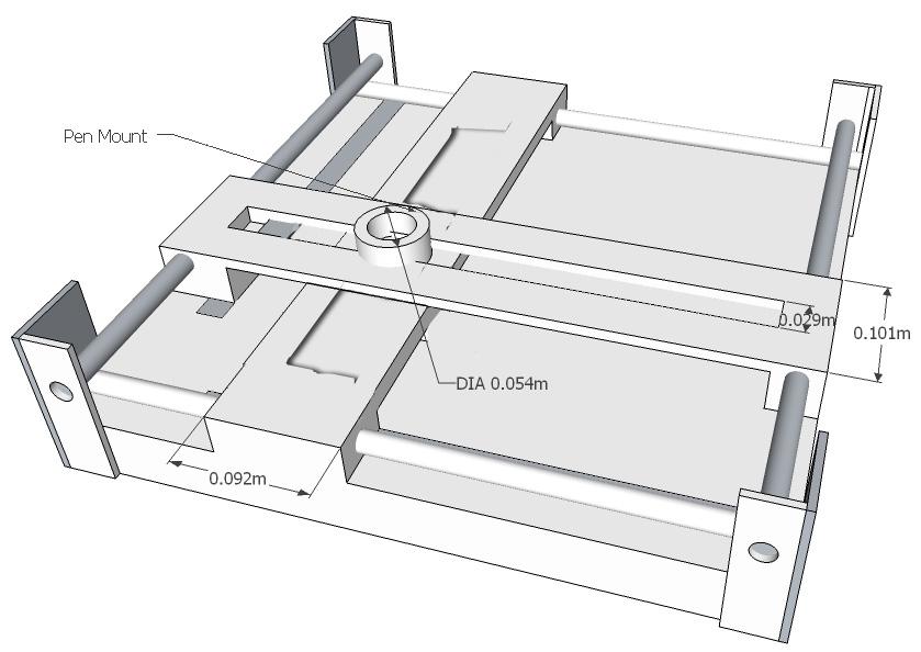
Two thin wooden boards with a cut-out center are mounted crisscross on the sliders. The pen mounting mechanism is then positioned in the intersection of the two boards (see Illustration 6). It should move smoothly as the sliders are positioned in the x and the y directions. For this plotter, an empty wire-wrapping cable spool was cut in half and placed in the opening. To re-attach the two halves, a 3” strip of thin cardboard was rolled up and pushed inside the spool, holding the two pieces together.
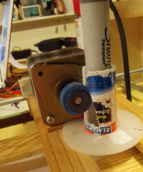
The print head was initially designed using a large electromagnet mounted on top of a round tube. A sharpie with a metal washer glued to the top was placed underneath the magnet, and a relays circuit was designed to activate the relay. The circuit worked on the bread board, but the GPIO pin did not provide sufficient current to activate the relay, so after some failed attempts to fix the circuit, a new approach using a stepper motor was devised (see Illustrations 7). The new way was actually easier to use and more reliable.
The print head is secured in the intersection of the two rails using a small cable spool that was cut in half. An empty glue stick tube (any tube with the correct diameter will work as long as it can be cut easily) that is positioned in the middle of the spool holds the top and bottom part together. By removing the bottom, the print head assembly can be removed easily. A thin slit is cut in the side of the tube so that the rotating shaft of a motor mounted next to it will be positioned in front of the opening. A rubber band is then wound along the shaft so that it will secure a pen in place inside the tube. Moving the stepper motor clockwise or counter-clockwise will now raise or lower the pen easily.
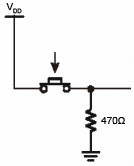
For calibration and feedback, four limit switches were added to at each end of the the two rails. The buttons were designed using a pull-down resistor (see Illustration 8), and they were wired to four GPIO pins. By reading the button status, the driver can determine if it has reached the end of a rail. The calibration information could also be used to calculate the step size by counting the number of steps from one button event to the next, and dividing the total length of the rail by the number of steps. A closeup of one limit button is shown in Image 9.
Hardware Interface
The stepper motor are controlled using two STMicroelectronics L298N Full-bridge motor drivers, which are attached to the SJSU-One ARM-based controller board (see Illustration 10).
The L298N can control a 4-wire bipolar stepper motor using a 4-bit binary input. It is possible to control up to four motors with a 4 of 16 decoder such as a 74LS154. We are currently using a 4-to-16 decoder to control the three motors used for the plotter.
Electronic Design
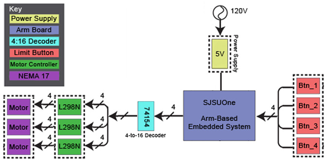
The system diagram in Illustration 11 shows the key components of the electrical system designed to control the prtinter.
Power Supply
The 5V power supply is used to power the stepper motor controllers and the microcontroller. However, during development, the system board is powered via a USB cable since the same cable is used for programming the hardware.
SJSUOne Board
The SJSUOne board is an ARM-based microcontroller running FreeRTOS. It is used to communicate with the external hardware via GPIO pins.
Limit Buttons
The limit button (Btn_1 though Btn_4) are used to provide feedback about the horizontal and vertical position of the print head. THe button is triggered when any of the two sliders has reached the end of a rail.
4-to-16 Decoder (74153)
The decoder is used to activate a particular coil in the stepper motor. A 4-to-16 decoder can control up to four motors, but it can only run one motor at a time. Each motor required 4 consecutive output pins on the decoder.
L298-Based Stepper Motor Controller
Each of the three stepper motor controllers is wired to the decoder and to one of the stepper motors. It activates a particular coil in the motor that is attached to it based on the input from the decoder. For example, 0010 activates coil 3 in motor one.
Motor
The motors used in this system are standard NEMA 17 type stepper motors common in plotters and 3D printers. This bi-polar stepper motor has 4 wires to control four coils in the motor.
Limit Switches
Each limit switch is hooked up to one GPIO input pin. In our implementation, the following pins were used:
- Button 1: P1:26
- Button 2: p1:27
- Button 3: p0:4
- Button 4: p0:5
Stepper Motor Controller
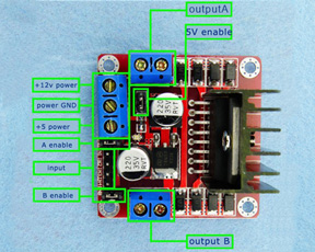
While there is a wide variety of stepper motor controllers, the one we used is shown in Illustration 12. It uses an L298 chip for motor control, and it is powered by a 5V power supply. While the controller can handle higher voltages, 5V provides sufficient power, and the chip quickly overheats when using 12V. The four input controls on the stepper motor controller are connected to the outputs for each pin as shown below:
| Decoder Input | DEcoder Output Pin | Motor # | Stepper Controller Input Pin |
|---|---|---|---|
| 0000 | 0 | 1 (Horizontal Control) | 1 |
| 0001 | 1 | 1 (Horizontal Control) | 2 |
| 0010 | 2 | 1 (Horizontal Control) | 3 |
| 0011 | 3 | 1 (Horizontal Control) | 4 |
| 0100 | 4 | 2 (Vertical Control) | 1 |
| 0101 | 5 | 2 (Vertical Control) | 2 |
| 0110 | 6 | 2 (Vertical Control) | 3 |
| 0111 | 7 | 2 (Vertical Control) | 4 |
| 1000 | 8 | 3 (Pen Control) | 1 |
| 1001 | 9 | 3 (Pen Control) | 2 |
| 1011 | 10 | 3 (Pen Control) | 3 |
| 1011 | 11 | 3 (Pen Control) | 4 |
The schematic for this motor setup is shown in Illustration 13.
Stepper Motor Wiring
While NEMA 17 is a standard form factor for stepper motors, not all NEMA 17 motors are wired identical. Our motors were wired as follows:
- Ground: Orange (connected to output A), Blue (connected to output B)
- Coils 1,3: Red (connected to output A)
- Coils 2,4: Yellow (connected to output B)
To determine which wires are paired, simply test the resistance through a pair of wires.
Software Design
The current printer driver consists of the printerTask(), which is scheduled in the main function. The function of this task is to listen to a button event to run a test program. All the task-related functions are kept in a dedicated printer library, which consists of the printer.hpp header file and the code library printer.cpp.
printer.hpp
bool motor_init();
bool motor_control(int motor, bool direction, int duration, int speed);
void setproperinputoutputs();
void gotoorigin();
bool buttonpress(int motor, bool direction);
int speed_y;
int speed_x;
The motor_init() function configures the GPIO pins and sets the speed for the motors that move the print head horizontaly and vertically. Motor torque is inversely related to the motor speed. Since the horizontal motor belt is very tight, the motor speed has to be lowered to provide sufficient torque to be able to pull the belt. Therefore, the speed settings for the two motors are
Print Speed Settings
speed_y = 6;
speed_x = 2;
The GPIO settings are as follows:
GPIO Settings
LPC_GPIO1->FIODIR |=  (1 << 19); // Set Pen Holder CS as output
LPC_GPIO1->FIODIR |=  (1 << 20); // Set Decoder Enable as output
LPC_GPIO1->FIODIR |=  (1 << 22); // Set MotorControl as Output
LPC_GPIO1->FIODIR |=  (1 << 23);
LPC_GPIO1->FIODIR |=  (1 << 24);
LPC_GPIO1->FIODIR |=  (1 << 25);
LPC_GPIO1->FIODIR &=  ~(1 << 26); // Set Sensing Button as Input
LPC_GPIO1->FIODIR &=  ~(1 << 28);
LPC_GPIO1->FIODIR &=  ~(1 << 30);
LPC_GPIO1->FIODIR &=  ~(1 << 31);
LPC_GPIO2->FIODIR0 = 0x00; // Set Buttons as Input
The decoder circuit is responsible for controlling all three stepper motors for the project. The required sequence to control any one motor is 4’b0111, 4’b1011’ 4’b1101’ and 4’b1110 for clockwise operation. Reversing the inputs will produce a counter-clockwise rotation. An input of 4’b1111 or 4’b0000 will not affect the current position of the stepper motor. Therefore, to control the motor, we simply need to set the decoder as shown in the table in the Stepper Motor Controller section. Since the decoder output is active low, 4'b1000 will produce the output 16'b0000:0010:0000:0000, which moves motor 3 to position the pen. The partial code for the motor_control() function is shown below. THis function takes 4 arguments including the motor number and the direction, and moves the motor selected by the integer motor clockwise or counterclockwise based on the direction value.
Controlling Motors
/* Select the motor (1-4) */
if((motor % 2)) {
  LPC_GPIO1->FIOSET = (1 << 24);
} else {
  LPC_GPIO1->FIOCLR = (1 << 24);
}

if((motor/2) % 2) {
  LPC_GPIO1->FIOSET = (1 << 25);
} else {
  LPC_GPIO1->FIOCLR = (1 << 25);
}

/* Move Motor for duration amount of time */
for(int i = 0; (i < duration) && status; i++)
{
/* Have decoder count from 0-3 */
if(direction) {
  LPC_GPIO1->FIOCLR = (1 << 22);
  LPC_GPIO1->FIOCLR = (1 << 23);
  vTaskDelay(speed);

  LPC_GPIO1->FIOSET = (1 << 22);
  LPC_GPIO1->FIOCLR = (1 << 23);
  vTaskDelay(speed);

  LPC_GPIO1->FIOCLR = (1 << 22);
  LPC_GPIO1->FIOSET = (1 << 23);
  vTaskDelay(speed);

  LPC_GPIO1->FIOSET = (1 << 22);
  LPC_GPIO1->FIOSET = (1 << 23);
  vTaskDelay(speed);
}
One exampe of controlling the motor is the gotoorigin() function:
Function to Position Print Head to Start Position
void printerTask::gotoorigin()
{
    motor_control(2,1,20,speed_x);
    motor_control(0,0,480,speed_y);
    motor_control(1,0,465,speed_x);
    motor_control(0,1,20,speed_y);
}
The gotoOrigin function is different from regular print functions because the print duration ( the third value passed to the motor_control() function can exceed the maximum possible number of steps since the limit switches will indicated to the plotter that the print head has reached the origin. For any other vector, the duration needs to be determined based on the length of the vector and the resolution (step width) of the motors, a value that can be obtained using the formula
resulution = distance / stepCount
The stepCount in this formula is the total number of steps as the print head is moved, for example, button_1 to button_2.
The limit switches are checked using the buttonPress() function:
Reading the Limit Switches
status = buttonpress(motor, direction);
Implementation
To print, a pen is placed in the print head assembly. The pen diameter should be large enough so that it is held in place by the motor shaft. To ensure the correct height, we marked the pen's top position. The ideal type of pen for printing is a Sharpe since it does not require a lot of pressure for drawing. However, to use a Sharpie, the pen needs to be removed after printing to replace the cap on the pen.
To start the print job, ensure the cap is removed, position the pen, and hit button 5 on the development board. Button 5 will launch the test print routine, and the plotter will output 'HELLO'.
Testing & Technical Challenges
Testing
During development, a simple driver was created that could be used to control the motors through the push buttons on the SJSUOne board, and that did assign one direction to each push button. Once design was completed, a test pattern output routine was created that did print some predefined text. While the current output is hard-coded, the task of devising a more universal routine is trivial. This can easily be accomplished by devising an array of vector coordinates for each letter, and translating an input string to the corresponding letter array element to obtain the necessary coordinate points. Obviously, these points have to be treated as being relative to the current pen position.
Challenges
We encountered several unexpected problems during the hardware design phase. Some of the biggest problems were mechanical in nature. Some of the issues we encountered are discussed below.
Positioning of the Print Head
Moving the sliders did prove more difficult than expected. The problem was not so much a programming issue as it was caused by the mechanical properties of the design, in particular the belts used. It was difficult to find the right type of belts using recycled components, and at least one belt was too fine for the motor and the gears to properly move it. Attempts to replace the belt once the printer was completed proved very difficult since any attempt to cut and glue the belt always produced a new belt that was either too loose or too tight. We finally went with a fairly tight belt that forced us to lower the overall speed of the system to ensure that the motor has sufficient torque to move theis belt.
Print Head Design
The print head design was a problem for several reasons. For once, the general design took a while to figure out. Once that was done, the next problem was how to control the electromagnet from the SJSUOne board. Since we were unable to find a relay that worked with 3.3V, we used a NOT gate to put out the 5V to switch the relay, and utilized the 12V supply from our power supply to power the electromagnet. This worked well on a breadboard, but the circuit did not work when in conjunction with the SJSUOne board. After some tests, it was determined that the problem was most likely that the relay required a current that exceeded the current that was supplied by the GPIO pin. Instead of spending more time on this design, the print head was completely re-designed using a motor to push the pen up and down in a plastic tube.
Motor Control
The initial problem we encountered was how to control the stepper motors. Not only did we lack sufficient instructions for the salvaged motors, but we also had attempted to design the motor controller from scratch. This did proof too time consuming. We finally decided to purchase a set of NEMA 17 stepper motors, the standard motor used in most hobbyist 3D printers. We also did purchase several low-cost stepper motor controllers on eBay. However, even with the new motors, a problem was to actually create the driver since non of the instructions did appear to work since the wiring on the motors was different than what the wiring instructions expected. We finally found instructions how to easily determine the wiring of a stepper motor on the website below:
Mechanical Issues
Finding the right design to allow the sliders to move freely was probably the most challenging aspect of the hardware design. After we tried cabinet wheels and hollow metal rows, we used a block of wood with a guide hole. The secret was to keep the piece wide enough so that it does not get pulled at an angle. However, even this solution is not ideal, and we would suggest using linear ball bearings instead. Additionally, it is important to ensure that parallel rails are indeed parallel. Otherwise, the sliders will not move smoothly. We were forced to remove the bottom of the sliders to turn the hole into a half-circular groove.
Another problem was that one of the salvaged timing belts was designed for finer gear than what the motors were equipped with. This resulted in excessive slippage during operation, which could only be corrected by finding another belt and replacing the existing one. This required completely disassembling one side of the plotter. Since there was no fitting belt, a longer belt had to be cut to size and glued. A process that was not trivial.
Conclusion
In conclusion, the project proved much more difficult than we expected it to be. There were some problems with the programming part, but the biggest challenge was the mechanical aspect of the design. However, we gained several valuable insights in what not to do in our final project. For example, the decoder approach to controlling the motors does not allow us to control several motors simultaneously. This would be a problem when trying to achieve the high precision necessary for 3D printing.
Another problem was the quality of the mechanical design. The plotter project has shown that we will not be able to build a well working project like a plotter or a 3D printer using recycled parts and leftover wood. This project helped us realize that to create a good project, we need to invest in quality materials.
Interestingly, some of the biggest challenges also proved to be the most rewarding moments. In particular, the redesign of the print head taught us one valuable lesson. Sometimes stepping back and discarding a flawed approach for a completely new approach can result in a new design that is far better than the original idea. It is therefore not always a good thing to stubbornly hold on to an idea!
Project Video
SJSU - Spring, 2013 - CMPE 146 - 2D Plotter saying "HELLO"
Project Source Code
References
Acknowledgement
We wish to thank Preet for continuously challenging us and showing us a large variety of different technologies that we usually do not get to explore hands-on in our lectures.
