Difference between revisions of "S17: Logan"
Proj user3 (talk | contribs) (→Software Design) |
Proj user3 (talk | contribs) (→Software Design) |
||
| Line 368: | Line 368: | ||
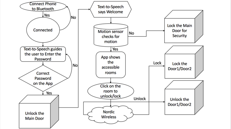
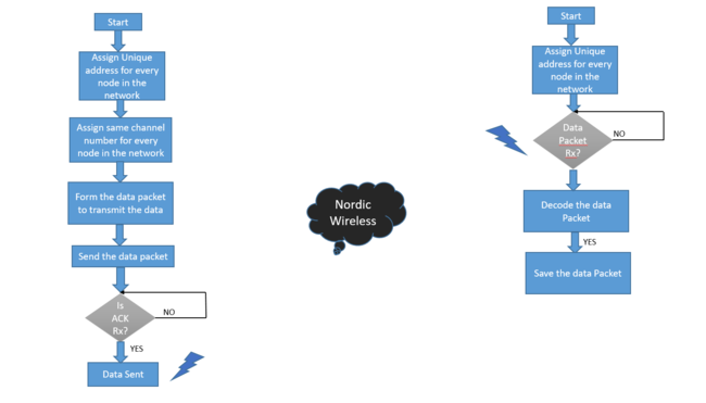
| − | [[File:CMPE244_S17_Logan_Nordic_Wireless_Flowchart.PNG|center| | + | [[File:CMPE244_S17_Logan_Nordic_Wireless_Flowchart.PNG|center|650px|thumb|Nordic Wireless Flow-Chart]] |
Revision as of 12:25, 25 May 2017
Contents
- 1 Logan The Smart Lock
- 2 Abstract
- 3 Objectives & Introduction
- 4 Schedule
- 5 Parts List & Cost
- 6 Design & Implementation
- 7 Testing & Technical Challenges
- 8 Conclusion
- 9 References
Logan The Smart Lock
Abstract
A staggering 1.4 billion smartphones were sold in 2015. An average consumer checks his or her smartphone 46 times a day, and in the US, people do this a collective 8 billion times every 24 hours. Most people at some point lose or forget to bring their key. Our Smart Lock system provides an alternate convenient way of access control on a user's smart phone. Smart Lock can simplify life and increase home security. Smart Lock provides a mechanism to lock and unlock your door with your Smart Phone, using Bluetooth communication with password protection. The door locks/unlocks automatically when the correct password is entered on the Mobile App and the motion sensor senses the motion when a person approaching from the inside towards the exit in order to lock the door to provide security. We are using Nordic Wireless communication to access multiple locks in this project. Another additional feature in the project is interfacing the Text-to-Speech in order to inform/guide the users at every step.
Objectives & Introduction
- Locking/Unlocking of the Electric Door Strike using a Mobile App over Bluetooth
- Design of Printed Circuit Board (PCB) to simplify the hardware system design
- Combination of PIR Motion sensor and Mobile App to increase security
- Accessing the other locks using the Nordic Wireless
- Text-to-Speech to guide the User at every step
Team Members
Roles & Responsibilities
- Harsha Gorantla
- Text-to-Speech Module, PCB Design and Complete System Algorithm
- Krishank Mehta
- Hardware Design and assembling, Software Flow, PCB design, PIR sensor and Door Strike
- Prashant Aithal
- Mobile App, PCB Deisgn and Nordic Wireless Communication
- Shruthi Narayan
- PCB design, Bluetooth and Testing
Schedule
| Sl. No | Start Date | End Date | Task | Status | Actual Completion Date |
|---|---|---|---|---|---|
| 1 | 03/21/2017 | 03/28/2017 | Project proposal submitted | Completed | 03/21/2017 |
| 2 | 03/28/2017 | 04/04/2017 | Research on the whole system flow and deciding on components Assign individual task Order the components |
Completed | 04/04/2017 |
| 3 | 04/04/2017 | 04/11/2017 | Implementation of the PIR sensor with the SJ one board Initial circuit design of PCB |
Completed | 04/11/2017 |
| 4 | 04/11/2017 | 04/18/2017 | Integration and testing of Electric Door strike functionality Design of PCB for bluetooth, PIR sensor, SJOne, door-strike related pins on the PCB |
Completed | 04/18/2017 |
| 5 | 04/18/2017 | 04/25/2017 | Integration of door strike with PIR sensor Interface Bluetooth module with SJOne board Design of the Android Mobile app. |
Completed | 04/25/2017 |
| 6 | 04/25/2017 | 05/02/2017 | Verify communication between Bluetooth module and Android app Extending the functionality to multiple locks using Nordic Wireless. |
Completed | 05/02/2017 |
| 7 | 05/02/2017 | 05/07/2017 | Integration of Text-to-Speech module Individual system testing. |
Completed | 05/07/2017 |
| 8 | 05/07/2017 | 05/14/2017 | Integration of the whole system Debugging and testing of the whole system. |
Completed | 05/14/2017 |
| 9 | 05/14/2017 | 05/21/2017 | Final testing and fine tuning Report preparation. |
Completed | 05/21/2017 |
Parts List & Cost
| Item# | Part Description | Vendor | Qty | Cost |
|---|---|---|---|---|
| 1 | SJ One Board (LPC 1758) | From Preet | 3 | $240 |
| 2 | Battery | From Amazon | 1 | $31.57 |
| 3 | Battery Charger | From Amazon | 1 | $17.50 |
| 4 | Bluetooth Module | From Sparkfun | 1 | $24.95 |
| 5 | Electric Door Strike | From Amazon | 3 | $72 |
| 6 | [PCB] | From PCBWay | 5 | $13 |
| 7 | PIR Motion Sensor | From Amazon | 1 | $9.95 |
| 8 | Relays(1 Channel DC 5v relay) | From Amazon | 5 | $16.50 |
| 9 | Text-to-Speech | From Amazon | 1 | $69.45 |
| 10 | [ Wires] | From Amazon | 1 | $3.95 |
Design & Implementation
System Block Diagram
Printed Circuit Board
Design
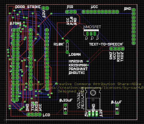
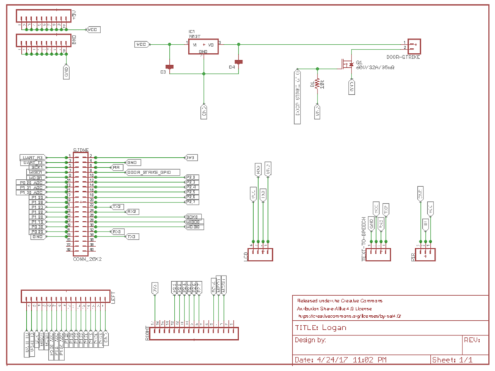
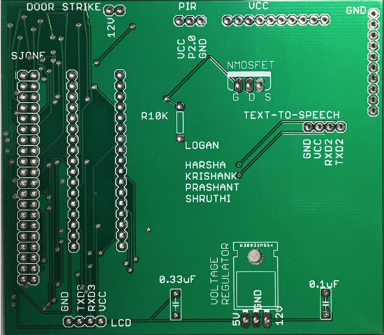
We have designed a custom Printed Circuit Board (PCB) to reduce hardware complexity. The dimensions of the PCB is 3.56 X 3.16 Inch to interface our SJOne board with Text-to-Speech, PIR Sensor, 1-Channel Relay and Electric Door Strike. It is worth designing the PCB as it reduced the hardware complexity and saved lot of wires. The PCB was designed and printed to house the circuit. To design our custom PCB board, we used Autodesk EAGLE PCB software version 8.2.0 which is a free software available online. EAGLE stands for, Easily Applicable Graphical Layout Editor which contains a schematic editor, for designing circuit diagrams. Before starting the PCB design, we downloaded all additional libraries from outside sources such as Sparkfun and Adafruit, to order required components easily.
The tool provides various connectors and devices which are commonly used in PCB’s. The tool is very easy to use. It is just a drag and drop and make connections to join different ports. In our PCB design, we used a lot of connectors with different pin configuration for various peripherals ranging from 3-pin to 20-pin connectors.
Eagle PCB Design Tool
The PCB layout editor allows back annotation to the schematic and auto-routing to automatically connect traces based on the connections defined in the schematic. The layout of the devices and interconnections on the board showcases both the top and bottom layers. The blue lines indicate the connection made from the bottom and red lines from the top. We have used through holes to avoid shorting the pin connections.
We planned the design and positioned the components to ease the accessibility of the pins and ports. We designed a custom 3.56x3.16 inch PCB to integrate different modules together along with the SJOne board. In order to minimize noise, a power copper layer as well as a ground copper layer were added to the top and back of the board. This cleaned up the wiring a lot, since every component contained these wires.
After the schematic and board files were completed, we chose PCB fab company called PCB Way since they deliver the PCBs very fast and it is also cost effective. This company is known for reliability, and quick turn around time. In addition to this, their website is very user friendly and designed for hobbyist. We submitted gerber files along with .sch and .brd files. We chose FR-4 grade printed circuit boards (PCB) because they are flame-resistant. FR-4 is a composite material composed of woven fiberglass cloth with an epoxy resin binder. Our design went through the design checking process and when approved, they were manufactured. In total, the PCB took days from submission of payment to receiving the board. We also coordinated with other teams and ordered PCB together to share the shipping cost.
Connector List
| Purpose | Device | Library | Package | Port/Pin Connected |
|---|---|---|---|---|
| SJSUone Board | CONN_20X2 | SparkFun-Connectors | 2X20 | |
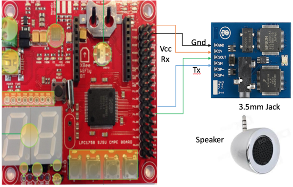
| Text To Speech | CONN_04 | SparkFun-Connectors | 1X04 | UART2 |
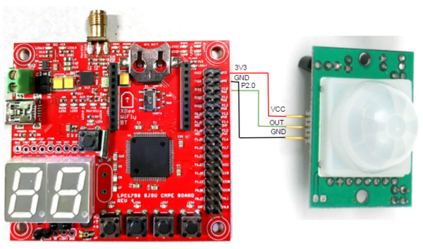
| PIR Sensor | CONN_03 | SparkFun-Connectors | 1X03 | Port 2.0 |
| Electric Door Strike | CONN_02 | SparkFun-Connectors | 1X02 | Port 2.1 |
PIR Motion Sensor
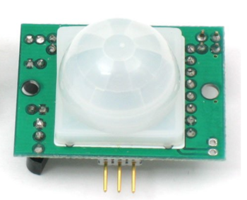
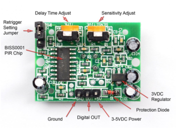
PIR (Passive Infrared )Motion sensor is an inexpensive, small sensor used to detect the human motion. The sensitivity or the range of the PIR sensor is 6 meters(or 20 feet) and works on a 3.3V input power supply. Once the device is powered, we have to wait 2-4 seconds to start using the device. The range of the sensor is 2 meters.
The sensor in a motion detector is actually split in two halves. The reason for that is that we are looking to detect motion (change) not average IR levels. The two halves are wired up so that they cancel each other out. If one half sees more or less IR radiation than the other, the output will swing high or low.
Hardware Design
Discuss your hardware design here. Show detailed schematics, and the interface here.
3D Printing for PIR Mount
Dimensions:
CURA software
Software Design
Electric Door Strike
One Channel Relay
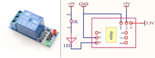
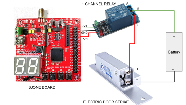
We have used a 1-Channel relay to control the Electric Door Strike from GPIO. The 1-Channel relay is active low circuit and the A and B are internally connected by default(NC). When a input of logic 1 is applied from GPIO to the relay, since the relay is active low, there will be no connection between B and C(NO). The circuit is not complete and so the Electric Door Strike will be locked. On the other hand, when a logic 0 is applied as Input to relay from GPIO, the B and C will be connected which completes the circuit. Hence the Electric Door Strike can be unlocked when the logic 0 is applied.
We need a battery, 1-Channel Relay and SJOne board to complete the Electric Door Strike circuit.
Hardware Design
Software Design
Mobile App
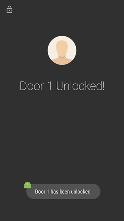
The android app was built using Android Studio using the Java programming language. Multiple activities corresponding to the different screens of the app were created. Bluetooth was implemented as a background service which allowed us to transmit the data across multiple screens of the app. The service also needs to be added in the Android Manifest xml.
Hardware Design
Discuss your hardware design here. Show detailed schematics, and the interface here.
Software Design
Code snippet on how to create a bluetooth service.
public class BluetoothService extends Service {

  @Override
  public int onStartCommand(Intent intent, int flags, int startId) {
      //TODO do something useful
      return Service.START_NOT_STICKY;
  }

  @Override
  public IBinder onBind(Intent intent) {
    //TODO for communication return IBinder implementation
    return null;
  }
}
Nordic Wireless
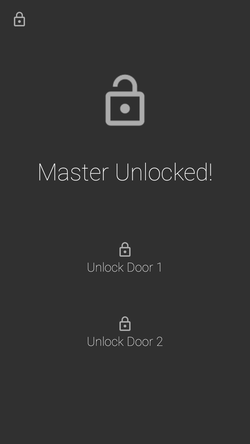
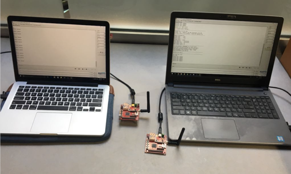
We have used Nordic Wireless communication to unlock/lock the Door 1 and Door 2 from the Master Lock. Master lock communicate with the Slave locks using onboard Nordic wireless IC. The mesh network drivers were used to interface with the Nordic IC. The Nordic nRF24L01+ is a highly integrated, ultra low power 2Mbps RF transceiver IC for the 2.4GHz ISM (Industrial, Scientific and Medical) band. The Nordic nRF24L01+ integrates a complete 2.4GHz RF transceiver, RF synthesizer, and baseband logic. We had to attach a RP-SMA Connector antenna to communicate between the multiple nodes. Nordic wireless can be used in multiple applications such as smart homes, games, consumer electronics and PC peripherals. We made use of Preet’s Low Powered Mesh Network stack.
Each packet is sent via an existing route, and if route has changed, a new route is automatically discovered using a special retry packet. Each node's ACK contains some meta-data about the node itself. This data includes information about its routing table, and other statistic. Duplicate packets are absorbed but an ACK is still replied if it's a duplicate, but a retry packet. An ACK packet or a response to an ACK all use retries; even the repeating nodes participate to make sure the packet is delivered. The minimum payload is 9 bytes, of which, 8 bytes will be the mesh header overhead. The higher the payload, the higher the efficiency of the network. The eight bytes of payload header contains the network source and destination information, along with packet type and hop count information.
For example, if the payload size is 32 bytes, then 8 bytes are used by the network header and 24 bytes are free to be used for transmitting the data.
The mesh_packet_t is a structure that is used to transmit the data to understand the data of the wireless packet. It has 4 struct variables.
- nwk : Packet network address
- mac : packet physical address
- info:Packet header
- Data:uint8_t type of data that is sent..
In this example, a commander sends an "Application Ack" packet, meaning that the destination will have to manually send an acknowledge packet back. In other words, instead of auto-acknowledge, we send the ACK back with the requested data. Furthermore, we show you how data variables can be exchanged between two boards. A wireless Tx task was created which was used to handle the wireless Nordic transmissions.
Hardware Design
Software Design
Here are some of the Nordic wireless API we used for our project.
1. This function is responsible for forming the packet wherein the address of the packet, type of mesh protocol used, the number of hops, number of data which will be sent, the actual data and their respectives size if sent.
wireless_form_pkt(&pkt2,addr2,mesh_pkt_ack,hops2,1,&var12,sizeof(var12));
2. The function sends the data packet to the particular node which is identified by the addr[noOfNodes] parameter. Upon receiving the data packet the node sends the acknowledgement back to the sending node which is stored in mesh_pkt_ack_app. The parameter hops give the distance between the two nodes
wireless_send_formed_pkt(&pkt2);
3. This function returns true if the data is received.
wireless_get_rx_pkt(&pkt,100)
4. This function is responsible for decoding the packet wherein the address of the packet, the number of hops, number of data which will be sent, the actual data and their respective size will be received.
wireless_deform_pkt(&pkt,2,&var1,sizeof(var1),&var2,sizeof(var2));
This function is responsible for sending the formed packet to all three slave nodes.
Code samples:
Transmit packet:
        wireless_form_pkt(&pkt,addr,mesh_pkt_ack,hops,2,&var1,sizeof(var1),&var2,sizeof(var2));

		wireless_send_formed_pkt(&pkt);
		if(wireless_get_ack_pkt(&pkt,1000))
		{
			u0_dbg_printf("Got ack\n");
		}
Receive packet:
       if(wireless_get_rx_pkt(&pkt,100))
		{
			wireless_deform_pkt(&pkt,2,&var1,sizeof(var1),&var2,sizeof(var2));
			u0_dbg_printf("%c\n",var1);
			u0_dbg_printf("%f\n",var2);
		}
Text-to-Speech
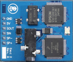
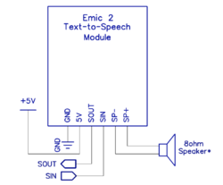
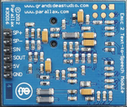
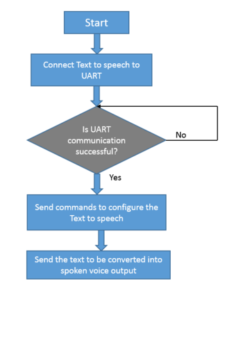
Emic 2 Text-to-Speech module converts the digital text to natural sounding speech. It uses UART to communication with the SJOne board. The Text-to-Speech (TTS) module is connected to the UART2 on the SJOne board. We can pick any voice from the 9 different voices and the volume can also be changed using the various commands. The in-built 3.5mm jack is used to connect the TTS to any speaker/earphones.
The key features are mentioned below:
- High-quality speech synthesis for English and Spanish languages
- Nine pre-defined voice styles comprising male, female, and child
- Dynamic control of speech and voice characteristics, including pitch, speaking rate, and word emphasis
- Industry-standard DECtalk text-to-speech synthesizer engine (5.0.E1)
Hardware Design
Software Design
Commands:
- Sx Convert text-to-speech: x = message (1023 characters maximum)
- Dx Play demonstration message: x = 0 (Speaking), 1 (Singing), 2 (Spanish)
- X Stop playback (while message is playing)
- Z Pause/un-pause playback (while message is playing)
- Nx Select voice: x = 0 to 8
- Vx Set audio volume (dB): x = -48 to 18
- Wx Set speaking rate (words/minute): x = 75 to 600
- Lx Select language: x = 0 (US English), 1 (Castilian Spanish), 2 (Latin Spanish)
- Px Select parser: x = 0 (DECtalk), 1 (Epson)
- R Revert to default text-to-speech settings
- C Print current text-to-speech settings
- I Print version information
- H Print list of available commands
Text-to-Speech code snippet:
    Uart2 &u2=Uart2::getInstance();

	ttsTask (uint8_t priority) : scheduler_task("ttsTask", 2048, priority)
	{

	}
	bool init(void)
	{
		u2.init(9600,200,200);
		u2.putline("V18", portMAX_DELAY); // volume control
		return true;
	}
	bool run(void *p)
	{
		u2.putline("SHello", portMAX_DELAY);
        //In the Sx command, S is to get the speech output and x refers to the data string, Text-to-Speech will say 'Hello' in this case
        return true;
	}
Testing & Technical Challenges
Describe the challenges of your project. What advise would you give yourself or someone else if your project can be started from scratch again? Make a smooth transition to testing section and described what it took to test your project.
Include sub-sections that list out a problem and solution, such as:
Issue #1
The current was not enough from the SJOne board to unlock the Electric Door Strike. We initially decided to use a N-MOSFET as a switch to control the Electric Door Strike from GPIO pin but the current is not enough to switch the N-MOSFET. So, We have used 1-Channel relay to supply proper current.
Issue #2
The first issue that we faced with Nordic Wireless was buying the RP-SMA connector which needs to be attached to the SJ One board. The RP stands for Reverse Polarity. The below diagram clears any doubts regarding the connectors. The RP-SMA Female Antenna were difficult to obtain.
Issue #3
In Nordic Wireless, the channel number needs to constant if you wish to communicate between the multiple nodes in the same network, meanwhile each node in the network needs to have a unique node address. These parameters can be changed in the sys_config.h file. This file provides the configurable parameters of the project.
Issue #4
The Android app requires us to create a RF Communication and a Bluetooth socket. We set up the bluetooth connection on the UI Main thread. While it does serve the purpose of transferring data in the current screen of the application, it is not feasible to transfer data across multiple screens of the mobile application. It is generally advisable to create any network related tasks on a separate thread. Hence we implemented the Bluetooth as a background service. This enabled us to transmit data via bluetooth across multiple screens of the mobile application.
Issue #5
Faced lot of issues while parsing the data between the activity and service of the app.Data needs to be transmitted from the activity and service with the help of intents along with the putExtra() method.
Conclusion
This project was so much fun to work on. The project has increased our knowledge in both hardware and software know-how. We have interfaced PIR sensor, Text-to-Speech module and designed a mobile application to communicate over bluetooth. We got hands-on experience with the UART and Wireless communication. This project has provided an opportunity to delegate and work in a team. We defined our own objectives, overcame the challenges and successfully completed the project.
Project Video
Upload a video of your project and post the link here.
Project Source Code
References
Acknowledgement
We would like to thank Preet for the guidance and the support. The learnings in the class has helped us in the successful implementation of this project.
