Difference between revisions of "S17: Sky Knight"
Proj user6 (talk | contribs) (→PID Controller) |
Proj user6 (talk | contribs) (→PID Controller) |
||
| Line 428: | Line 428: | ||
The value of I is supposed to be less than P, but if I is greater than P then it will have a overshoot and if the value of I is too less than P, then we observe some vibrational motions of the Quad-copter. So the value of I should be less than P, but high enough to avoid vibrations. | The value of I is supposed to be less than P, but if I is greater than P then it will have a overshoot and if the value of I is too less than P, then we observe some vibrational motions of the Quad-copter. So the value of I should be less than P, but high enough to avoid vibrations. | ||
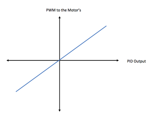
| − | [[File:CMPE244 S17 SkyKnight Graph.png|500px| | + | [[File:CMPE244 S17 SkyKnight Graph.png|500px|left|thumb|Figure 4: Graph]] |
| + | |||
We need to calculate the slope of the frequency vs PWM graph. We can calculate it using minimum and maximum values of frequency and PWM which we will be using in the algorithm. This value can differ for different systems. We can use below the formula: | We need to calculate the slope of the frequency vs PWM graph. We can calculate it using minimum and maximum values of frequency and PWM which we will be using in the algorithm. This value can differ for different systems. We can use below the formula: | ||
Revision as of 07:00, 25 May 2017
Contents
Grading Criteria
- How well is Software & Hardware Design described?
- How well can this report be used to reproduce this project?
- Code Quality
- Overall Report Quality:
- Software Block Diagrams
- Hardware Block Diagrams
- Schematic Quality
- Quality of technical challenges and solutions adopted.
Sky Knight
Abstract
We have implemented a quad-copter capable of self-sustained flight. Our quad-copter has 4 arms with propeller and motors on each. The propellers generate thrust that lifts the quad-copter against the gravity. ESCs (Electronic Speed Control ) are used to control the motor rotation speed depending on the PWM provided by SJOne board. We have implemented the self-stabilizing technique using PID algorithm. Android Application is also developed to provide user interface to control the motion of our quad-copter. The communication between android application and SJOne board is done using Bluetooth.
Objectives
The main objective of this project is to implement the following.
- Design and build an efficient hardware so that it is easy to mount on Quadcopter.
- Interface the BNO055 sensor with LPC1758 to get pitch, roll and yaw angles.
- Develop Android Application to control the motion of the quadcopter and communicate with SJOne via Bluetooth.
- Analyze PID algorithms and tune the PID algorithm that will stabilize the flight of Quadcopter.
Introduction
Basics
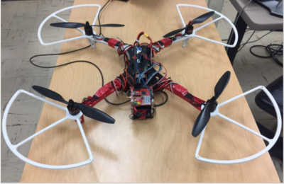
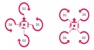
- Quad-copter can be 'X' and '+' configuration. We have used 'X' Configuration.This configurations more responsive than '+' configuration and it is convenient to add Camera in 'X' configuration.
- In 'X' configuration, Diagonally opposite motors are rotated in the same direction as can be seen in the adjacent diagram.
- Motors D2, D3 are rotated in clockwise direction and Motors D5, D6 are rotated in anti-clockwise direction.
- These 4 rotating propellers will generate lift in upward direction and when this lift is greater that the gravitational force then the quad-copter will fly.
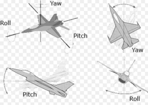
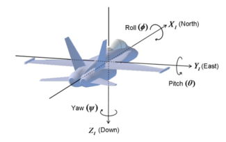
- There are three axis of rotation to describe the orientation of quad-copter.
- The angle of rotation around the three axis are yaw, pitch and roll.
- Rotation around front-to-back axis is called pitch.
- Rotation around side-to-side axis is called roll.
- Rotation around the vertical axis is called yaw.
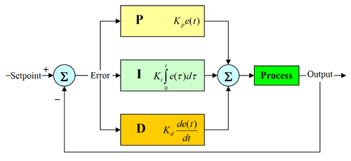
A PID system is a type of control system, where we regulate the input signal using feedback signal. PID algorithm is very important for quad-copter as it requires high level of stability to hover in the air. PID stands for Proportional, Integral and Derivative. The P term simply generates a response to motors which is directly proportional to the error angle. The D term is used to reduce the errors our system is going to make in the future. It is calculated as error/(time between consecutive reading). So if the P term is giving some more response than required, D term will minimize it to a value lower than set point. Integral term collects the errors in the past and covers up for those errors, so that the correction will bring the system exactly to the set point.
The PID equation is written as:
PID Output = Kp * P + Kd *D + Ki * I;
where,
Kp = Proportional constant
Kd = Derivative constant
Ki = Integral constant
Team Members & Responsibilities
Schedule
| Sr. No | Start Date | End Date | Task | Status | Actual Completion Date |
|---|---|---|---|---|---|
| 1 | 2/21/2017 | 2/28/2017 |
|
Completed | 2/28/2017 |
| 2 | 2/28/2017 | 3/14/2017 |
|
Completed | 3/14/2017 |
| 3 | 3/14/2017 | 3/28/2017 |
|
Completed | 3/29/2017 |
| 4 | 3/14/2017 | 4/11/2017 |
|
Completed | 4/15/2017 |
| 5 | 4/11/2017 | 4/25/2017 |
|
Completed | 4/25/2017 |
| 6 | 4/15/2017 | 4/25/2017 |
|
Completed | 4/18/2017 |
| 7 | 4/25/2017 | 5/01/2017 |
|
Completed | 5/01/2017 |
| 8 | 5/2/2017 | 5/8/2017 |
|
In Progress | |
| 9 | 5/9/2017 | 5/25/2017 |
|
Parts List & Cost
Give a simple list of the cost of your project broken down by components. Do not write long stories here.
| Qty | Description | Manufacturer | Part Number | Total Cost |
|---|---|---|---|---|
| 1 | FPV 4-Axis Quadcopter Frame kit w/ Protective Guard | UFO | $41.00 | |
| 1 | Adafruit 9-DOF Sensor | Adafruit | BNO055 | $39.97 |
| 1 | Quadcopter Power Distribution Board | Hobby King | $10.00 | |
| 1 | PCB | PCBWay | $27.00 | |
| 4 | OPTO Brushless ESC | ARRIS 2-6S 30AMP | $53.00 | |
| 4 | 6045 Carbon Nylon Propellers | Gemfan | $4.00 | |
| 1 | SJOne Board | Preet | LPC1758 SJSU Board | $80.00 |
| 1 | x2204 2300kv Brushless Motors - set of 4 | SunnySky | SNS-X2204S-KV2300 | $63.00 |
| 2 | 4000mAh 3S 30C Lipo Battery Pack | Turnigy | T4000.3S.30 | $22.00 |
| 1 | 50W 5A Balancer Charger | Hobbyking | ECO6 | $19.00 |
| 1 | 105W 15V/7A DC power supply | Hobbyking | 9052000023-3 | $15.00 |
| 1 | 3.5mm Gold Connectors | Polymax | $2.00 | |
| 1 | Long Nylon Threaded Spacers | $6.00 | ||
| 1 | Test Environment Frame for testing | Home Depot | $15.00 | |
| Total Cost (excluding shipping and taxes) | $397.00 |
Design & Implementation
Hardware Design
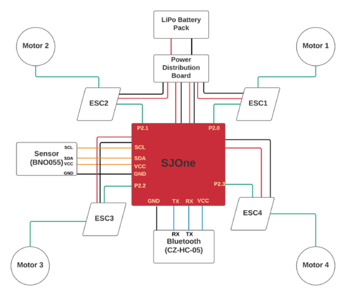
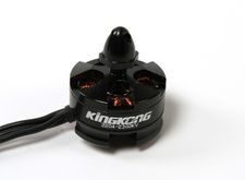
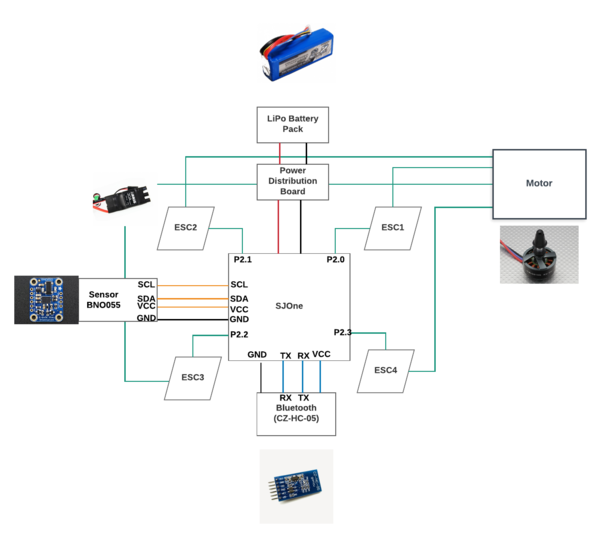
For making of quadcopter a SJOne board is used on which flight controlling software was implemented. This board reads the value from the BNO055 sensor and generates the PWM (Pulse Width Modulation) pulse to drive the four motors. In this project we used four 2300KV brushless servo motor are used. 2300 KV means that for each one volt applied to motor it will produce an RPM of 2300. A 11.6v LIPO battery was used to provide the power supply to the motor's via a power distribution board.
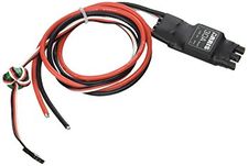
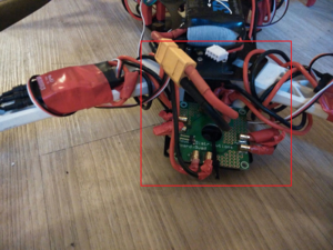
We have used 4 OPTO Brushless ESC of 30 Amp, to make the motor spin based on the PWM provided by the SJOne board. The ESC is capable of delivering 30 A of continuous current to the motors. Before using the ESC we need to calibrate the ESC by providing the max and min PWM that it is gonna function in. The Wires connected from the ESC to motor are able to support high Supply of Current. A Separate board is design, which act as an interface between the SJOne board to ESC & Bluetooth. An external 5V Supply was used to provide the power to the SJOne Board , which in-turn provided power to the bluetooth module.
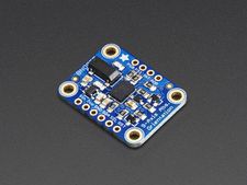
A 4 axis UFO with propeller guard is being used for this project. The frame and the guards were mainly used considering our requirement and safety reasons. We have also used a BNO055 9 DOF Adafruit sensor, which is been interfaced with the SJOne. An I2C data communication takes place between the Sensor and the LPC Board , to send the data from the sensor to the board whose values are been used to stabilize the flight of the Quadcopter.
Motors
We have implemented Brushless motors for our quadcopter. They are much more powerful and energy efficient, unlike DC motors. The kV rating on the motor indicates how many RPM the motor can rotate for the given number of volts. Brushless motors work by producing magnetic fields to produce electric charges. The speed of the spinning motor is controlled by an ESC. In our Quadcopter we have 2 motors on the diagonals moving in clockwise while the other two in anti-clockwise.
Electronic Speed Controller (ESC)
We have used ESC (Electronic Speed Control) to control the motor rotation speed also to set its direction (clockwise or anti-clockwise ).The ESC will control the PWM values provided to it by LPC 1758 board. Our ESC runs at about 400 Hz with pulse widths that range from 3.12ms to 6.25 ms. 3.12 ms turns off the motor input while 6.25 ms makes the motor run at max speed. The OPTO brushless ESC is programmable, and has several different parameters for the user to configure.
Sensor
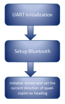
We are using BNO055 sensor to measure the orientation of our quad-copter.This sensor is 9-axis absolute orientation sensor. It has an advanced tri-axial 16 bit gyroscope, a versatile, leading edge tri-axial 14 bit accelerometer and a full performance geomagnetic sensor. We get fused sensor data output of Quaternion, Euler angles, Rotation vector,Linear acceleration, Gravity, Heading. We have interfaced BNO055 sensor with SJOne board using I2C. We are getting Pitch, Roll and Yaw angle with 16 bit precision and giving these values as input to our PID controller to maintain the stable orientation.
Bluetooth
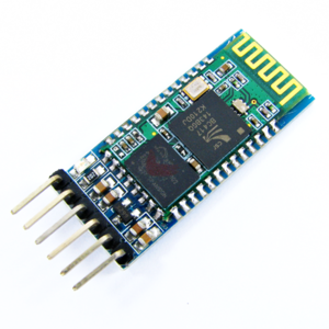
We are using bluetooth HC-05 module as medium of communication between SJONE board and android phone. There is one way communication from Android phone to SJONE i.e. to send the commands. The Bluetooth module is interfaced to SJONE using UART communication. The bluetooth module can be configured to support baud rates of 9600,19200,38400,57600,115200,230400,460800 but we are using the default baud rate o 38400.
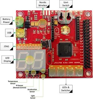
SJOne Flight Controller
SJOne was used as a controller for the flight of the Quadcopter. We have interfaced Bluetooth, Sensor and PCB (used for interfacing with the motor). Each of this modules are controlled by the board. We have controlled the Flight of the Quadcopter using Android app. The board will be provided with the information through app and will compute the PWM values and provide it to the ESC. The Board will process the data provided from the sensor and will compute the values of P , I and D for Yaw , Pitch and Roll. SJOne Board controls every aspect required for the quadcopter to fly. Every activity should go through the SJOne i.e it is used as a medium of communication. FreeRTOS is used on the board. We have used FreeRTOS task for periodically calling various functions.
Android Application
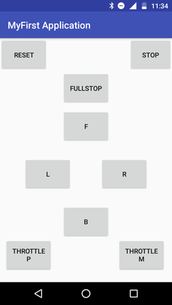
Android Application is used to control the quad-copter. We have created the the simple user interface.
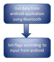
This application allows user to start and stop the quad-copter. We have configured two activities in our application. In first activity that is in first page we have one button that connects to the Bluetooth and once Bluetooth connection is established , application is navigated to second page. In this second page, we have provided users the buttons to control the quad-copter. Total 9 buttons are provided to user. The names and the functionality of each button is as follows:
1) RESET : This button starts the quad-copter.
2) STOP : This button helps user to stop the quad-copter slowly.
3) FULLSTOP : This button stops the SJOne board. Thus, immediately stops the quad-copter.
4) F : This button moves the quad-copter in the Front direction.
5) L : This button moves the quad-copter in the Left direction.
6) B : This button moves the quad-copter in the Back direction.
7) R : This button moves the quad-copter in the Right direction.
8) Throttle P : To increase the throttle. This increases the PWM value by 0.02 when pressed.
9) Throttle M : To decrease the throttle. This decreases the PWM value by 0.02 when pressed.
PCB Design
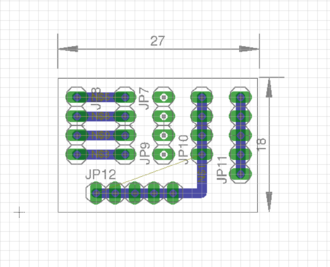
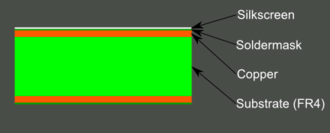
A Printed Circuit Board or PCB is a plate or board used for placing the different elements that conform an electrical circuit that contains the electrical interconnections between them.The most simple printed circuit boards are the ones that contain copper tracks or interconnects only on one of its surfaces. These kinds of boards are known as 1 layer printed circuit board or 1 layer PCB.The most common PCB's manufactured today are the ones that contain 2 layers, that is, you can find interconnects in both surfaces of the board. However, depending on the physical complexity of the design ( PCB layout ), the boards can be manufactured with 8 or more layers. Ours is 1 layer PCB. Our PCB design consisted of Silkscreen and Soldermask on the top side and copper layer on the bottom side.
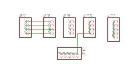
We made a PCB to connect the PWM signal pins of the SJONE board to ESC's signals pins and also provide VCC and GND to the peripherals.Designing PCB in Eagle is a 2 step process. First, design a schematic and then use the designed schematic for board representation.Eagle's board and Schematic work hand-in-hand.
Circuit Schematic or Schematic The Schematic is the representation of the electronic system using abstract, graphic symbols. Drawing a Schematic is always the first step of designing a PCB. Usually, PCB design software contains separate tools for Schematic and PCB design. Often a PCB is represented by multiple Schematic pages separated by functions, like power domain, analog signal domain, inputs/outputs.You can use the libraries provided by Adafruit or Eagle to get the components to your schematic.
Layer Overview PCB composition is all about layering one material over another. The thickest, the middle part of the board is an insulating substrate (usually FR4). On either side of that is a thin layer of copper, where our electric signals pass through. To insulate and protect the copper layers, we cover them with a thin layer of lacquer-like solder mask, which is what gives the PCB color (green, red, blue, etc.). Finally, to top it all off, we add a layer of ink-like silkscreen, which can add text and logos to the PCB.
Checking for Error
- The first check is to make sure you’ve actually routed all of the nets in your schematic. To do this, hit the RATSNEST icon.
- Once you’re done routing there’s just one more check to be made: the design rule check (DRC).To do this you need to download DRC Library. You should expect “DRC: No errors.”
Generating Gerbers Gerber files – note the plurality – each describes single layers of the PCB. One Gerber might describe the silkscreen, while another defines where the top copper is. In all, we’ll generate seven Gerber files to send to the fab house.
- CAM Processor - we "Process Job" to create the Gerber files.
- Picking a PCB Manufacturer - We picked PCBWay for the manufacturing of our PCB.
- Delivering the Gerbers - We generated GTL, GBL, GTS, GBS, GTO, GBO and the TXT files and send them this.
Hardware Interface
The protocols used for the interfacing are:
- I2C : For the communication between the SJOne and Sensor (BNO055). Since I2C is fast communication protocol and values from sensor decides the entire flight so this protocol was used.
- UART : Bluetooth and SJOne communication was made using this protocol.
- GPIO : All the ESCs' were connected using GPIO pins as can be viewed in the diagram above.
Software Design
PID Controller
The important part of the project was to make the Quad-copter stable, for which we have used PID algorithm. PID stands for Proportional, Integral and Derivative algorithm. PID is a closed loop system which computes the values of the error based on the values obtained from the Sensor. We had an initial Set-point value in our code, which as obvious would be the ideal error values that we expect from our Quad-copter. For computation of the P, we used the difference between the Set Point and the angle that you got from the sensor, this provides us the error. Then for computing , we take the difference of current error and previous error and divide that value with the time interval between them. For our case the time interval was 0.01s, since we are obtaining the values from the sensor in 100HZ task. Now even after using the values of P and D to minimize the error, we have to use I since it doesn't totally make the value of the error entirely zero. So in case of I we calculate the sum of last 6 error i.e. cumulative sum of previous 6 error. I keeps track of the small errors we failed to correct in the past and provides little bit extra correction to support P. Note : We always take the absolute value of I as error can be positive and negative and it can cancel the summation effect.
Observation:
When P is too high , the Quad-copter will correct itself beyond the Set-Point, but if P is too less, it will give slow response and may not become stable.
Usually the value of D should be less compared to P. But if the value of D is greater than P, then it provides an incorrect response i.e. consider the scenario when you want to turn RIGHT, but if the value of D is greater than P, it will take a LEFT. If D is too less, then it wont correct the overshoot error made by P and then the system will overshoot.
The value of I is supposed to be less than P, but if I is greater than P then it will have a overshoot and if the value of I is too less than P, then we observe some vibrational motions of the Quad-copter. So the value of I should be less than P, but high enough to avoid vibrations.
We need to calculate the slope of the frequency vs PWM graph. We can calculate it using minimum and maximum values of frequency and PWM which we will be using in the algorithm. This value can differ for different systems. We can use below the formula:
PWM variant = Slope * PID output;
We need to add/subtract this PWM variant in the current PWM value to stabilize the Quadcopter. First, we will get the output from all three PID controllers and then we will set the PWM value. We can make the function to set the PWM and call it after execution of all three PID controllers.
Implementation
In this section we will discuss our plan for the Implementation of this project using Software Design.
Android application will communicate with LPC1758 using Bluetooth HC-05 module. LPC1758 is interfaced with Bluetooth HC-05 using UART. We will be using four ESCs (Electronic Speed Controller) to drive four motors of Quad-copter. We will be giving PWM signals from LPC1758 to these four ESCs. We have used BNO055 which has 9 Degree of Freedom. This Sensor breakout has accelerometer, gyroscope, magnetometer and barometric sensor. We can get pitch, roll and yaw angle values from accelerometer, gyroscope and magnetometer with 16 bit precision. Barometric sensor is used to calculate the altitude of the Quad-copter using the pressure. Sensor is interfaced with LPC1758 using I2C communication. In I2C communication, we need to connect four wires. SDA pin of LPC1758 will be connected to SDA pin. SCL pin of LPC1758 will be connected to SCL pin. Ground and Vcc pins of sensor and LPC1758 will be connected. We need to give power from LPC1758 to sensor so we need to connect Vcc pin and both grounds should be common.
Testing & Technical Challenges
1) Weight Distribution - First challenge to us was to distribute the weight of the things on quad-copter in even manner. Weight distribution is important to ensure flight stability. Of course we have PID algorithm to ensure stable flight, but it is our responsibility to distribute weight in proper manner and minimize the work of PID in any way possible. Things like motors, propellers are already in correct place in terms of weight distribution since the chassis was designed accordingly. Things that we needed to place correctly and that had significant weight were battery, SJONE board, Power bank, ESCs, power distribution board. We placed the ESCs on each arm of the quad-copter i.e. near the motors. In the middle part of the chassis we placed SJONE on one end and on other end we placed Power Distribution board. We placed the battery exactly at the middle part of the upper layer and the power bank is also placed at middle part of the lower layer.
2) Battery Issues - Initially we used Turnigy LiPo 3000mAH battery and it worked well. But as we used it seemed like it stared to die quickly and eventually both of our Turnigy batteries were dead. The reason for this was that we used incorrect charger to charge these batteries. So we bought a new LiPo eRobotics battery and its proper charger to suffice our requirement.
3) Motor Issues - During testing we damaged two to three motors as they got over heated and hence we had to replace them.
4) Power Distribution - At the beginning we had build our own power distribution board to distribute power using solder iron and solder material. It took input power from the battery and distributed to the four different port which are connected to the ESCs. But during testing our power distribution board was burnt twice and probably that was the reason for our motor getting over heated. So we ordered a good power distribution board online.
5) ESC - One of our ESC started to act haywire. We configured all the ESCs to respond to PWM pulses between 40 to 80 for 400Hz frequency. But due to only one ESC that particular motor was rotating fast for the same PWM pulse as compared to other motors. So we had to discard that ESC and use a new one.
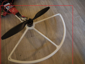
6) Propellers - When we started testing we broke several of our propellers are they were not guarded. Later we bought guards to protect the propellers and also some extra propellers as a backup.
7) Orientation Sensor - We were using CMPS11 sensor that gave us orientation in terms of roll and pitch angles. We were not considering yaw angle at that point. But after reading a lot about quad-copter discussions we found that the 8 bit precision of that sensor was not enough for stable flight. So we replaced the sensor with BNO055 that gave us 16 bit precision of roll, pitch and yaw values which was more that enough for the stable flight.
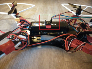
8) Sensor issue due to motor magnetic field - We observed that when we placed the sensor in the same plane of the motor, it use to get affected by the field and it gave incorrect values. We verified this by keeping the sensor in same position and by checking the reading when motor is on as well as off. So when elevated the sensor such that it is not in the same plane as that of the motors. Hence we placed the sensor over the battery.
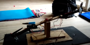
9) PID - The biggest challenge of all we faced was the PID algorithm. This challenge was so big that it took us a lot of time to understand it well and then implement it. We were doing it all wrong at the beginning. We were trying to fly our quad-copter which was incorrect and of course the quad behaved weird with that algorithm. Also we were running the algorithm with 10Hz task but we understood later that 10hz is very slow to process the algorithm and hence we switched to 100hz task. We knew we had to have a testing setup to get the PID algorithm correct. So we built the seesaw setup such that each end of the wooden plate has motor mounted to it. Then we wrote the PID algorithm for two motors such that the seesaw would balance itself. We perfected our PID algorithm with this setup. You can see the video 'PID Testing using Seesaw stand' below in videos section.
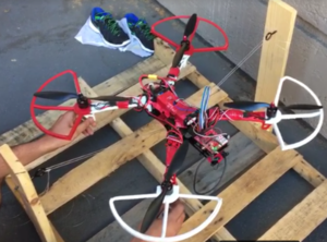
10) Testing challenge in real field - After we got our PID algorithm correct, we decided to built a wooden structure to mount our quad-copter and test it as shown in the image. We mounted our quad-copter using nylon wires to the hook at the side and tested whether the PID algorithm is able to keep it stable or not.
Conclusion
This project was a big challenge to us and was difficult to implement it in small time. But it was a great learning lesson overall to everyone of us. We learned many important things like basics requirement for quad-copter and its configuration, understanding of PID algorithm, hard real time software implementation and structural aspects of a quad-copter. The most important thing that we learned is to solve real world problems with correct approach. We successfully overcame the challenges and were able to achieve smooth flight of quad-copter.
Project Video
On Field Testing Initial Phase https://youtu.be/lQm-Qdt1894
Quad-copter Rope Tied Testing https://youtu.be/-ZVfokUFFPo
PID Testing using Seesaw stand: https://youtu.be/ftO13CeKirc
Quad-copter Stand Mount Testing https://youtu.be/Me5hdb_TkGU
Quad-copter Hover Video https://youtu.be/R3oFnWLibLk
Final Flight: https://youtu.be/scjI6HGl9Ao
Quad-copter Back Motion Control Video https://youtu.be/y9nNN9IHd-w
Quad-copter Backward and Right Motion Video https://youtu.be/z-7jj8FxK8c
Project Source Code
References
Acknowledgement
Any acknowledgement that you may wish to provide can be included here.
References Used
List any references used in project.
Appendix
You can list the references you used.
