Difference between revisions of "S17: Squad"
(→Get normalized values of decoded remote control pulse width signals) |
(→Integration) |
||
| (20 intermediate revisions by 2 users not shown) | |||
| Line 2: | Line 2: | ||
== Abstract == | == Abstract == | ||
| − | The goal of our project is to design a quadcopter that | + | The goal of our project is to design a quadcopter that can fly and stabilize with the guidance of a remote controller. The software will use a PID control algorithm to stabilize the motor speeds according to the positional sensors. The hardware will consist of interfacing the SJSU One board with an Adafruit 10-DOF sensor, remote control and receiver, an electronic speed controller (ESC), and four brushless motors. |
= Introduction = | = Introduction = | ||
| − | The stabilization of quadcopters requires that all four rotors | + | The stabilization of quadcopters requires that all four rotors work together. The inputs of the PID system included the accelerometer, gyroscope, and magnetometer. The output is a PWM signal to the ESC, which then spins the motor. Our goal was to get the quadcopter to hover with a remote control. The flight controller is programmed into the SJSUOne board. Everything ranging from stabilization to remote control is handled on this board. A PID algorithm is used to handle stabilization. This algorithm has been previously tested and tuned further for our project. Most of our code configuration lied within setting proper normalized values of the remote, setting frequency settings, and interfacing to other I/O devices. We spent much of our time finding the proper PID coefficients to get the proper flight stabilization. |
== Objectives == | == Objectives == | ||
Our objectives include the following: | Our objectives include the following: | ||
| − | * | + | * Balanced system with the ability to pitch forward, pitch backward, roll left, roll right, yaw left, and yaw right with remote control. |
| − | * | + | * Hover in a relatively small area using a optical flow sensor. |
| − | |||
| − | |||
=== Team Members & Responsibilities === | === Team Members & Responsibilities === | ||
| Line 32: | Line 30: | ||
! scope="row"| 1 | ! scope="row"| 1 | ||
| 4/10/2017 | | 4/10/2017 | ||
| + | | 4/16/2017 | ||
| + | | Disassemble new quadcopter and install SJSUOne board in place of existing flight controller | ||
| + | | Complete | ||
| + | | 4/16/17 | ||
| + | |- | ||
| + | ! scope="row"| 2 | ||
| + | | 4/17/2017 | ||
| + | | 4/23/2017 | ||
| + | | Install sensors and start testing of motor controls | ||
| + | | Complete | ||
| + | | 4/30/17 | ||
| + | |- | ||
| + | ! scope="row"| 3 | ||
| + | | 4/24/2017 | ||
| 4/30/2017 | | 4/30/2017 | ||
| − | | | + | | Finalize motor controls and the correctness of all sensors |
| Complete | | Complete | ||
| 4/30/17 | | 4/30/17 | ||
|- | |- | ||
| − | ! scope="row"| | + | ! scope="row"| 4 |
| 5/1/2017 | | 5/1/2017 | ||
| 5/7/2017 | | 5/7/2017 | ||
| − | | | + | | Indoor PID tuning with a safe and controlled rig. |
| Complete | | Complete | ||
| 5/7/17 | | 5/7/17 | ||
|- | |- | ||
| − | ! scope="row"| | + | ! scope="row"| 5 |
| 5/8/2017 | | 5/8/2017 | ||
| − | | 5/ | + | | 5/14/2017 |
| − | | | + | | Completion of indoor PID tuning and attempt for outdoor fly testing. |
| Complete | | Complete | ||
| − | | 5/ | + | | 5/14/17 |
|- | |- | ||
| − | ! scope="row"| | + | ! scope="row"| 6 |
| − | | 5/ | + | | 5/15/2017 |
| − | | 5/ | + | | 5/21/2017 |
| − | | | + | | Attempt to integrate and tune optical flow sensor. |
| Complete | | Complete | ||
| − | | 5/ | + | | 5/21/17 |
|- | |- | ||
| − | ! scope="row"| | + | ! scope="row"| 7 |
| − | | 5/ | + | | 5/22/2017 |
| 5/24/2017 | | 5/24/2017 | ||
| − | | Final testing for | + | | Final testing and video for final demos. |
| Complete | | Complete | ||
| 5/24/17 | | 5/24/17 | ||
| Line 67: | Line 79: | ||
== Parts List & Cost == | == Parts List & Cost == | ||
| − | |||
{| class="wikitable" | {| class="wikitable" | ||
| Line 76: | Line 87: | ||
! width="60" align="center"|Total Cost | ! width="60" align="center"|Total Cost | ||
|- | |- | ||
| − | | align="center"|1|| | + | | align="center"|1||Tiean MJX Bugs Drone 3 Standard Quadcopter 2.4G 4CH 6-Axis Gyro Without Camera||Tiean||||align="right"|$149.99 |
| − | |||
| − | |||
| − | |||
| − | |||
|- | |- | ||
| align="center"|1||SJOne Board||Preet||LPC1758 SJSU Board ||align="right"|$80.00 | | align="center"|1||SJOne Board||Preet||LPC1758 SJSU Board ||align="right"|$80.00 | ||
|- | |- | ||
| − | | align="center"| | + | | align="center"|3||ANNONGONE 7.4V 25C 1800mAh LiPo Battery for MJX Bugs Drone 3||ANNONGONE||||align="right"|$30.00 |
| − | |||
| − | |||
|- | |- | ||
| − | | align="center"| | + | | align="center"|4||Quadcopter Spare Parts 4 PCS MJX B3 Propellers for MJX Bugs B3 Drone Remote Control Helicopter 2CW 2CCW Rotor Main Blades||Hobbylane||||align="right"|$8.00 |
|- | |- | ||
| − | | align="center"|1|| | + | | align="center"|1||CJMCU-110 Optical Flow Sensor Module APM2.52/2.6 ADNS 3080 Flight Controler||||||align="right"|$16.00 |
|- | |- | ||
| − | | align="center"|1|| | + | | align="center"|1||Spektrum DX6E 6Ch Transmitter||Spektrum||||align="right"|$199.00 |
|- | |- | ||
| − | | align="center"|1|| | + | | align="center"|1||7.4V 60A PSU||||||align="right"|$70.00 |
| − | |||
| − | |||
| − | |||
| − | |||
| − | |||
| − | |||
|- | |- | ||
| align="center"|1||Test Environment Frame for testing||Home Depot||||align="right"|$15.00 | | align="center"|1||Test Environment Frame for testing||Home Depot||||align="right"|$15.00 | ||
|- | |- | ||
| − | | ||Total Cost '''(excluding shipping and taxes)'''|| || ||align="right"|'''$ | + | | ||Total Cost '''(excluding shipping and taxes)'''|| || ||align="right"|'''$570.00''' |
|- | |- | ||
|} | |} | ||
| Line 135: | Line 134: | ||
| scope="row"|4||4||4||Throttle | | scope="row"|4||4||4||Throttle | ||
|- | |- | ||
| − | | scope="row"|5||5|| ||Arm/Disarm | + | | scope="row"|5||5||5||Arm/Disarm |
|- | |- | ||
|} | |} | ||
| Line 179: | Line 178: | ||
=== Motors === | === Motors === | ||
| + | |||
| + | The motors used in this project were originally the stock motors that came with the MJX Bugs 3 Drone, but once the project was switched to one with older parts the motors were SunnySky X2204S KV2300. These motors are quite powerful since they are made for quadcopters weighing a maximum of 1000grams. | ||
[[File: S15 146 G1 sunnysky.jpg|350px|center|thumb|Figure 3. Brushless Motors]] | [[File: S15 146 G1 sunnysky.jpg|350px|center|thumb|Figure 3. Brushless Motors]] | ||
| Line 184: | Line 185: | ||
=== Electronic Speed Controller (ESC) === | === Electronic Speed Controller (ESC) === | ||
| − | The ESC | + | The ESCs used in this project were originally the stock ones that came with the MJX Bugs 3 Drone, but event, but once the project was switched to one with older parts the ESC used was the Emax 4-in-1 25amp ESC. It includes four 25amp ESCs in one unit and was strong enough for the SunnySky motors. |
[[File: S15 146 G1 emax.jpg|300px|center|thumb|Figure 4. Electronic Speed Control]] | [[File: S15 146 G1 emax.jpg|300px|center|thumb|Figure 4. Electronic Speed Control]] | ||
| − | === | + | === Adafruit 10-DOF Sensor === |
| − | The | + | The Adafruit 10-DOF is a sensor that measures the orientation of the quadcopter. These sensors are important because they provide the necessary information needed to control the quadcopter. Included in the 10-DOF is an accelerometer, a gyroscope, a magnetometer, and a compass. This is the device that is used in conjunction with the SJSUOne board to compute proper angle values and for the remote control to request angles for pitch, roll, and yaw. |
[[File: S17_244_Squad_ Adafruit.jpg|300px||thumb|center|Fig. 5 Inertial Measurement Unit]] | [[File: S17_244_Squad_ Adafruit.jpg|300px||thumb|center|Fig. 5 Inertial Measurement Unit]] | ||
| − | === | + | === SJSUOne Flight Controller === |
| − | The | + | The SJSUOne board is programmed and configured to be the main flight controller of the quadcopter. The RC receiver, the sensor, and the ESC are all hooked up to the board. Each of these devices are actively working together and are controlled by the board. The receiver takes input from the RC and outputs it into the SJOne board. The board will process the requested PWM and will use this information to control the ESC. It will also process the requested angle of pitch and roll. The sensor readings will be used to process both the requested angle from the RC, and to process the flight stabilization calculations. This microcontroller controls every aspect required for the quadcopter to fly. Every action must first go through the SJOne board. FreeRTOS is extensively used on the board. Many critical actions such as remote control and flight stabilization are set up as tasks. The board will determine the priority given to each task. |
[[File: Sjone board.jpg|300px|center|thumb|Figure 6. SJOne Board]] | [[File: Sjone board.jpg|300px|center|thumb|Figure 6. SJOne Board]] | ||
| Line 245: | Line 246: | ||
[[File: S17 244 Squad Adafruit.jpg|250px]] | [[File: S17 244 Squad Adafruit.jpg|250px]] | ||
[[File: S17_244_Squad_quad.jpg|250px]] | [[File: S17_244_Squad_quad.jpg|250px]] | ||
| + | [[File: S17 244 Squad New drone that broke.jpg|250px]] | ||
== Testing & Technical Challenges == | == Testing & Technical Challenges == | ||
| Line 262: | Line 264: | ||
== Issue 2 == | == Issue 2 == | ||
| − | The original drone that was developed had a mechanical issue either with the ESC or the motor. This happened five days prior to the due date of the project and because we couldn't order another part in time we had to improvise by starting from scratch on an old drone. The old drone only had the motors, ESC, and frame installed. The SJSUOne board, sensors, and power supply had to be moved completely and the PID gains had to be re-tuned all over again. | + | The original drone that was developed had a mechanical issue either with the ESC or the motor. This happened five days prior to the due date of the project and because we couldn't order another part in time we had to improvise by starting from scratch on an old drone. The old drone only had the motors, ESC, and frame installed. The SJSUOne board, sensors, and power supply had to be moved completely and the PID gains had to be re-tuned all over again. We literally finished an entire semester worth of work in one day. |
== Issue 3 == | == Issue 3 == | ||
| Line 268: | Line 270: | ||
== Conclusion == | == Conclusion == | ||
| − | + | In this project, we utilized many new sensors that have never been used before such as the Adafruit accelerometer sensor, the ESC controller, and the remote transmit/receive sensor. We learned how to interface these new sensor with understanding each sensor's spec. The most important knowledge we have learned is adjusting the PID value in order to stabilize the quadcopter. We have a set of environment to test the drone's stability, and use our self-defined raw command to change the PID value. Finding the proper PID value for quadcopter is the hardest task in this project. We get a very stable PID value from our simulation environment and program into the quadcopter, but the quadcopter still very unstable in the real test. When testing quadcopter outside the room, there many unexpected situation such as wind and turbulence will have an affect on the outdoor flying. | |
| + | |||
| + | We encountered many hurdles in our first attempt at the quadcopter. We had initially thought that it would be simpler to buy a quadcopter off the shelf and replace the flight controller. This turned out to be a mistake since there was no documentation available for the ESC's. When we ran into trouble with the ESC towards the end of the project there was nothing we could do to debug or resolve the issue. We ended up having to resort to a completely different quadcopter. | ||
| + | |||
| + | When finally achieving stable flight with the quadcopter we realized that any disturbance by the wind would cause it to drift. We turned to the optical flow sensor. Trying to interface with this sensor turned out to be more difficult than we initially thought. We ran into timing issues when trying to read from the registers one at a time and ended up having to read multiple registers in what is called "burst mode." | ||
| + | |||
| + | In the end, we realized that quadcopters are not for the faint of heart, and require a huge amount of time and dedication. However, this was a very rewarding experience since it involved resolving issues stemming from many different engineering disciplines including electrical, mechanical, and software. | ||
=== Project Video === | === Project Video === | ||
https://www.youtube.com/watch?v=gkTlo5t4o04 | https://www.youtube.com/watch?v=gkTlo5t4o04 | ||
| + | https://youtu.be/ZWS9cOwkb_o | ||
=== Project Source Code === | === Project Source Code === | ||
Latest revision as of 02:58, 25 May 2017
Contents
Squad
Abstract
The goal of our project is to design a quadcopter that can fly and stabilize with the guidance of a remote controller. The software will use a PID control algorithm to stabilize the motor speeds according to the positional sensors. The hardware will consist of interfacing the SJSU One board with an Adafruit 10-DOF sensor, remote control and receiver, an electronic speed controller (ESC), and four brushless motors.
Introduction
The stabilization of quadcopters requires that all four rotors work together. The inputs of the PID system included the accelerometer, gyroscope, and magnetometer. The output is a PWM signal to the ESC, which then spins the motor. Our goal was to get the quadcopter to hover with a remote control. The flight controller is programmed into the SJSUOne board. Everything ranging from stabilization to remote control is handled on this board. A PID algorithm is used to handle stabilization. This algorithm has been previously tested and tuned further for our project. Most of our code configuration lied within setting proper normalized values of the remote, setting frequency settings, and interfacing to other I/O devices. We spent much of our time finding the proper PID coefficients to get the proper flight stabilization.
Objectives
Our objectives include the following:
- Balanced system with the ability to pitch forward, pitch backward, roll left, roll right, yaw left, and yaw right with remote control.
- Hover in a relatively small area using a optical flow sensor.
Team Members & Responsibilities
- Calvin Lai
- Jonathon Hongpananon
- Shangming Wang
Schedule
| Week# | Start Date | End Date | Task | Status | Actual Completion Date |
|---|---|---|---|---|---|
| 1 | 4/10/2017 | 4/16/2017 | Disassemble new quadcopter and install SJSUOne board in place of existing flight controller | Complete | 4/16/17 |
| 2 | 4/17/2017 | 4/23/2017 | Install sensors and start testing of motor controls | Complete | 4/30/17 |
| 3 | 4/24/2017 | 4/30/2017 | Finalize motor controls and the correctness of all sensors | Complete | 4/30/17 |
| 4 | 5/1/2017 | 5/7/2017 | Indoor PID tuning with a safe and controlled rig. | Complete | 5/7/17 |
| 5 | 5/8/2017 | 5/14/2017 | Completion of indoor PID tuning and attempt for outdoor fly testing. | Complete | 5/14/17 |
| 6 | 5/15/2017 | 5/21/2017 | Attempt to integrate and tune optical flow sensor. | Complete | 5/21/17 |
| 7 | 5/22/2017 | 5/24/2017 | Final testing and video for final demos. | Complete | 5/24/17 |
Parts List & Cost
| Qty | Description | Manufacturer | Part Number | Total Cost |
|---|---|---|---|---|
| 1 | Tiean MJX Bugs Drone 3 Standard Quadcopter 2.4G 4CH 6-Axis Gyro Without Camera | Tiean | $149.99 | |
| 1 | SJOne Board | Preet | LPC1758 SJSU Board | $80.00 |
| 3 | ANNONGONE 7.4V 25C 1800mAh LiPo Battery for MJX Bugs Drone 3 | ANNONGONE | $30.00 | |
| 4 | Quadcopter Spare Parts 4 PCS MJX B3 Propellers for MJX Bugs B3 Drone Remote Control Helicopter 2CW 2CCW Rotor Main Blades | Hobbylane | $8.00 | |
| 1 | CJMCU-110 Optical Flow Sensor Module APM2.52/2.6 ADNS 3080 Flight Controler | $16.00 | ||
| 1 | Spektrum DX6E 6Ch Transmitter | Spektrum | $199.00 | |
| 1 | 7.4V 60A PSU | $70.00 | ||
| 1 | Test Environment Frame for testing | Home Depot | $15.00 | |
| Total Cost (excluding shipping and taxes) | $570.00 |
Design & Implementation
Hardware Design
To make the quadcopter a SJOne board is used on which the flight controller software is developed. This board reads the sensors values and generates the PWM (Pulse Width Modulation) pulses to drive the four motors. In this project four KV2300 Sunnysky brushless servo motors are used. 2300KV means that for each one volt applied to the motor it will produce an RPM of 2300. The battery used in this project is 3cell 11.8V which roughly produces 27k rpm. Each of the motors are capable of lifting 500 grams on full throttle.
These motors are very fast so they draw a lot of current which can’t be provided by SJOne board, so too make the motors to spin the output of the SJOne board is fed into an ESC (Electronic Speed Controller). The EMAX ESC used is capabale of delivering 25 Amperes of continuous current for each motor. Wires to connect the motors to the ESC are 18AWG to be able to support the high current that motors are drawing. The battery is directly connected to the ESC which is used to power the four motors and part of it is also regulated to 5Volts which is used as the power source for other on board electronic systems. A separate power distribution board is designed which provides both 5 and 3.3 volts. The ADAFruit sensor board, along with five sonar sensors, and the remote control receiver which operate with 3.3 Volts receive their supply voltage from this board. The SJSU one board is also connected to this board for its 5Volt supply voltage.
A UFO frame with propellers guard (figure xx) is used for this project. This frame is mainly chosen for safety reasons since the propellers spin very fast and can be dangerous. The ADAFruit sensor board uses the I^2 C bus, so it is connected to SDA2 and SCL2 signals of SJOne board. The remote control receiver is connected to the GPIO pins as follows:
| No. | RC Channel | Receiver Channel | Description |
|---|---|---|---|
| 1 | 1 | 1 | Pitch |
| 2 | 2 | 2 | Roll |
| 3 | 3 | 3 | Yaw |
| 4 | 4 | 4 | Throttle |
| 5 | 5 | 5 | Arm/Disarm |
The four motors are connected to the PWM enabled GPIO ports of the SJOne board in following order:
| No. | Pin | Motor Direction |
|---|---|---|
| 1 | P2.0 | North |
| 2 | P2.1 | South |
| 3 | P2.2 | East |
| 4 | P2.3 | West |
Remote Control Transmitter & Receiver
The remote controller is for transmitting throttle, pitch, roll, and yaw angles from the controller to SJOne Board..
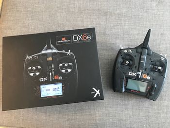
We used Spectrum DX6e model, which has 6 available channels and the operating frequency is 2.4GHz.
Channel 1 - Pitch
Channel 2 - Roll
Channel 3 - Throttle
Channel 4 - Yaw
Channel 5 - Arm/Disarm
Channel 6 - Hold position
Motors
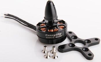
The motors used in this project were originally the stock motors that came with the MJX Bugs 3 Drone, but once the project was switched to one with older parts the motors were SunnySky X2204S KV2300. These motors are quite powerful since they are made for quadcopters weighing a maximum of 1000grams.
Electronic Speed Controller (ESC)
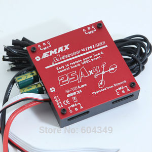
The ESCs used in this project were originally the stock ones that came with the MJX Bugs 3 Drone, but event, but once the project was switched to one with older parts the ESC used was the Emax 4-in-1 25amp ESC. It includes four 25amp ESCs in one unit and was strong enough for the SunnySky motors.
Adafruit 10-DOF Sensor
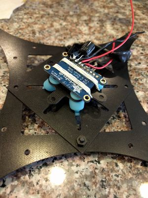
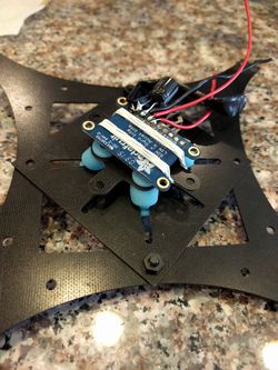
The Adafruit 10-DOF is a sensor that measures the orientation of the quadcopter. These sensors are important because they provide the necessary information needed to control the quadcopter. Included in the 10-DOF is an accelerometer, a gyroscope, a magnetometer, and a compass. This is the device that is used in conjunction with the SJSUOne board to compute proper angle values and for the remote control to request angles for pitch, roll, and yaw.
SJSUOne Flight Controller
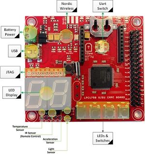
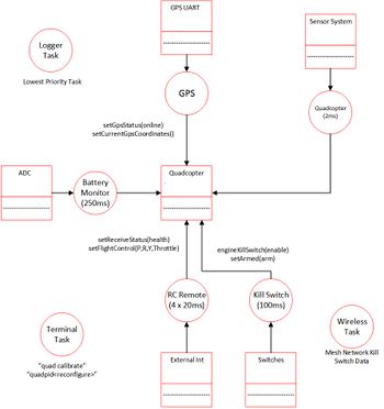
The SJSUOne board is programmed and configured to be the main flight controller of the quadcopter. The RC receiver, the sensor, and the ESC are all hooked up to the board. Each of these devices are actively working together and are controlled by the board. The receiver takes input from the RC and outputs it into the SJOne board. The board will process the requested PWM and will use this information to control the ESC. It will also process the requested angle of pitch and roll. The sensor readings will be used to process both the requested angle from the RC, and to process the flight stabilization calculations. This microcontroller controls every aspect required for the quadcopter to fly. Every action must first go through the SJOne board. FreeRTOS is extensively used on the board. Many critical actions such as remote control and flight stabilization are set up as tasks. The board will determine the priority given to each task.
Hardware Interface
Communication protocols used :
- UART - Serial communication via Hercules and telemetry.
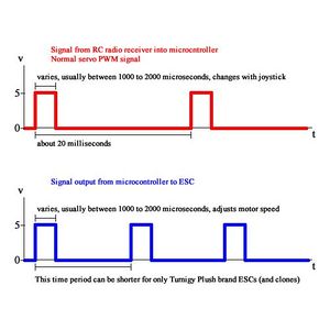
- PPM (Pulse Position Modulation) - Sequence of 6 channels of remote control transmitter signals into receiver on the quadcopter.
- Interrupts - Usage of the GPIO ports on the SJSU One board and the timer API to capture the PPM signals from the remote control transmitter to receiver.
- PWM (Pulse Width Modulation) - Decoding remote control signals into pulse signals the ESC's can use to drive the motors
- I2C I/O communication with the Adafruit 10-DOF sensor
- SPI I/O communication with the optical flow sensor
Software Design
Our software utilizes object oriented programming (OOP) concepts. There are many types of "objects" which hold data in our system. For example, mFlightControllerAngles holds the current setpoint angles for all axis, mCurrentAngles holds the current x, y, and z-axis angles, and mMotorValues holds the motor values which will be applied to the motors. There are several different classes which separate the different functions in the system. The lowest level class, MotorControllerIface is an abstract class which contains undefined virtual methods. These virtual methods are defined in inherited classes which will use them. The FlightStabilizer class is responsible for controlling flight parameters using the sensor data and controlling lower-level flight logic. The highest level class, QuadcopterBase, is defined for high-level flight logic such as autonomous GPS flying.
PID Controller
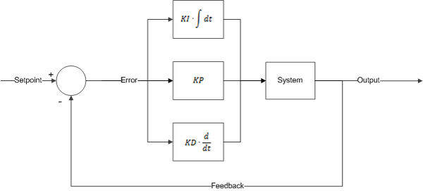
PID (proportional, integral, and derivative) is a closed-loop control system that tries to get results closer to the desired setpoint by adjusting the inputs of the system. The PID controller calculates an error, which is the difference between the measured variable and desired setpoint. The PID controller tries to minimizes the error throughout the operation. Our system takes the measured sensor data and compares against expected values (from the remote control) to alter the PWM output which will be applied to the ESC's and motors. The PID controller contains 3 separate parameters - proportional, integral, and derivative. P depends on the present, I on the accumulation of past errors, and D is a prediction of future errors based on the current rate of change. A higher P tries harder to stabilize itself - which can result in overshoot if too high. I attempts to reduce error based on past errors. The longer the error persists, then the more I will attempt to correct itself. Too much I can result in oscillations at lower frequencies. D attempts to dampen the system and prevent fast movements. However, too high of a D will also introduce oscillations.
Implementation
System Initialization
- Get the sensor inputs
- Update the flight sensor system data
- Update flying logic
- Run PID loop
- If timing is skewed, light up LED and increment TimingSkewedCount.
- If armed, apply motor values. Otherwise, apply value 0 to motors.
- if disarmed, reset all PID error values to 0 to avoid wind-up when arming again
Remote Control Signal Decoding
- Initialize ports for interrupt on rising and falling edges of inputs (6 channels)
- On rising edge of signal, start timer capture.
- On falling edge of signal, stop timer capture.
- Pulse width = stop - start
- Save timer value to their respective channel (pitch, roll, yaw, throttle, arm/disarm, and auxiliary)
Get normalized values of decoded remote control pulse width signals
- If throttle, scale from 0 to +100 for 0% to 100% by using a scaling factor and subtracting factor. Apply value to throttle of flight parameters.
- Otherwise, scale from -45 degrees to +45 degrees by using a separate scaling factor and subtracting factor. Apply values for requested flight angles.
- Set limits to avoid going out of bounds.
Integration
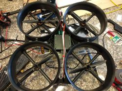
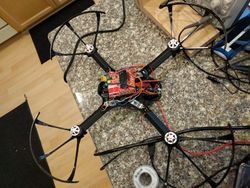
Below are pictures of the actual design and integration of the entire system.
Testing & Technical Challenges
PID Tuning Testing Methods
There are several ways to tune for PID. For this project we used brute force to tune the different axes, pitch, roll, and yaw. We designed a single axis gimbal device that would help us to tune a single axis at a time. By allowing freedom of movement along a single plane we can see when the quadcopter reaches its set point.
In order to tune the PID we first started with the Proportional gain. With just this gain applied to the algorithm, the quadcopter would oscillate around the set point at a constant rate. When this constant oscillation was reached, we then started to adjust the derivative gain. The derivative gain causes the steady oscillation already present to be critically damped and eventually settle on the set point.With only PD the quadcopter is already somewhat stable. The reason for including the integral portion is to allow the oscillations to settle faster. This is important since we want the quadcopter to become stable and reach its set point as quickly as possible. When we adjust the integral gain we increase it slowly until we see the quad copter reach its set point after the desired number of oscillations. If we were able to tolerate a higher number of oscillations then the PID controller would react faster and the quadcopter would actually settle on the set point more quickly. However, oscillations can also introduce instability during flight so for our application we are looking for 0 oscillations. Even though it causes us to reach our set point slower, it is a better option for us.
Stable PID Output
Once a stable PID controller has been achieved then any requests from the controller should result in the quadcopter being able to reach stability at the requested angle. Any attempts to knock the quadcopter off the set point causes the quadcopter to quickly return to its intended state.
Issues Faced
Issue 1
PID Tuning to achieve stabilization is the most difficult portion of the project. This involves knowledge of PID controls and how each gain (Proportional, Integral, and Differential) affect the stabilization of the drone.
Issue 2
The original drone that was developed had a mechanical issue either with the ESC or the motor. This happened five days prior to the due date of the project and because we couldn't order another part in time we had to improvise by starting from scratch on an old drone. The old drone only had the motors, ESC, and frame installed. The SJSUOne board, sensors, and power supply had to be moved completely and the PID gains had to be re-tuned all over again. We literally finished an entire semester worth of work in one day.
Issue 3
The optical flow sensor had communication problems at first. The specific part we chose had two options to receive the x-delta and y-delta values : 1) single register reads or 2) motion burst where 6 registers are read sequentially after the command is received. We had to learn the hard way that the motion burst was the more accurate way to receive the data we wanted.
Conclusion
In this project, we utilized many new sensors that have never been used before such as the Adafruit accelerometer sensor, the ESC controller, and the remote transmit/receive sensor. We learned how to interface these new sensor with understanding each sensor's spec. The most important knowledge we have learned is adjusting the PID value in order to stabilize the quadcopter. We have a set of environment to test the drone's stability, and use our self-defined raw command to change the PID value. Finding the proper PID value for quadcopter is the hardest task in this project. We get a very stable PID value from our simulation environment and program into the quadcopter, but the quadcopter still very unstable in the real test. When testing quadcopter outside the room, there many unexpected situation such as wind and turbulence will have an affect on the outdoor flying.
We encountered many hurdles in our first attempt at the quadcopter. We had initially thought that it would be simpler to buy a quadcopter off the shelf and replace the flight controller. This turned out to be a mistake since there was no documentation available for the ESC's. When we ran into trouble with the ESC towards the end of the project there was nothing we could do to debug or resolve the issue. We ended up having to resort to a completely different quadcopter.
When finally achieving stable flight with the quadcopter we realized that any disturbance by the wind would cause it to drift. We turned to the optical flow sensor. Trying to interface with this sensor turned out to be more difficult than we initially thought. We ran into timing issues when trying to read from the registers one at a time and ended up having to read multiple registers in what is called "burst mode."
In the end, we realized that quadcopters are not for the faint of heart, and require a huge amount of time and dedication. However, this was a very rewarding experience since it involved resolving issues stemming from many different engineering disciplines including electrical, mechanical, and software.
Project Video
https://www.youtube.com/watch?v=gkTlo5t4o04 https://youtu.be/ZWS9cOwkb_o
Project Source Code
References
Acknowledgement
Any acknowledgement that you may wish to provide can be included here.
References Used
http://www.rctoys.com/pr/2009/05/25/all-about-brushless-motors-what-you-need-to-know/
http://blog.oscarliang.net/quadcopter-pid-explained-tuning/
http://blog.opticontrols.com/archives/383
http://robotics.stackexchange.com/questions/167/what-are-good-strategies-for-tuning-pid-loops
