Difference between revisions of "S17: Interactive Snake and ladder"
Proj user2 (talk | contribs) (→Software Design) |
Proj user2 (talk | contribs) (→Parts List & Cost) |
||
| Line 161: | Line 161: | ||
| align="center"|1||Resistor 100ohm||||||align="right"| | | align="center"|1||Resistor 100ohm||||||align="right"| | ||
|- | |- | ||
| − | | ||Total Cost '''(excluding shipping and taxes)'''|| || ||align="right"|'''$ | + | | ||Total Cost '''(excluding shipping and taxes)'''|| || ||align="right"|'''$''' |
|- | |- | ||
|} | |} | ||
Revision as of 00:07, 25 May 2017
Contents
- 1 Project Title
- 2 Abstract
- 3 Objectives & Introduction
- 4 Schedule
- 5 Parts List & Cost
- 6 Design & Implementation
- 7 Testing & Technical Challenges
- 8 Conclusion
- 9 References
Project Title
Snake and Ladder
Abstract
This project aims to bring the fun and simplicity of snake and ladder game with some new features. It is a snake and ladder game using SJONE board, LCD and 2 wireless remotes. LCD display is connected to the SJONE board will display the game grid. It will also have the multiplayer feature that will allow more than one players to play the game using wireless remotes simultaneously. This project explores a new dimension in the traditional snake game to make it more interesting and challenging.
Objectives & Introduction
This game aims to change the way people think of traditional snake game. It will offer the experience of commercial multilayer games to the player retaining the simplicity of traditional snake game. The major objectives of this project are:
- To create a snake and ladder game that will have all the functionality of traditional snake and ladder games.
- Introduce multiplayer functionality in the game that will allow several players to play a game simultaneously. It should be able to give the experience of a real time multiplayer game to the players.
- To introduce Speech output for events.
Roles & Responsibilities
- Hardware and PCB designing
- Speech Module Interface and Algorithm
- LCD Interface and Game board Algorithm
- Wireless Communication
Schedule
| Week | Start Date | End Date | Task | Status | Actual Completion Date |
|---|---|---|---|---|---|
| 1 | 3/21 | 3/25 |
|
Complete | 3/25 |
| 2 | 3/25 | 3/29 |
|
Complete | 3/29 |
| 3 | 3/29 | 4/9 |
|
Complete | 4/10 |
| 4 | 3/29 | 4/8 |
|
Complete | 4/8 |
| 5 | 3/30 | 4/14 |
|
Complete | 4/14 |
| 6 | 4/11 | 4/20 |
|
Complete | 4/20 |
| 7 | 4/20 | 4/22 |
|
Complete | 4/22 |
| 8 | 4/23 | 4/31 |
|
Complete | 4/31 |
| 9 | 4/26 | 5/5 |
|
Complete | 5/6 |
| 10 | 5/5 | 5/21 |
|
In Progress | |
| 11 | 5/21 | 5/25 |
|
Plan |
Parts List & Cost
| Qty | Description | Manufacturer | Part Number | Total Cost |
|---|---|---|---|---|
| 1 | RA8875 Driver Board | Adafruit | $34.95 | |
| 1 | LCD Display | Adafruit | $47.50 | |
| 1 | Emic 2 Text to speech module | Parallax.inc | $60.00 | |
| 1 | PCB | PCBWay | $ | |
| 1 | Bergstrip male/female | |||
| 1 | LM-7805 | On-semiconductor | $0.43 | |
| 1 | LED | Kingbright | $0.19 | |
| 1 | Resistor 100ohm | |||
| Total Cost (excluding shipping and taxes) | $ |
Design & Implementation
Overall System
- The overall system is divided into 3 parts:
- game image display(LCD): the snake and ladder image grid is mounted on the 7 inches LCD screen.
- wireless SJONE board: the antenna is connected to SJONE board to transmit and receive signal from master. The basic use of the SJONE board with antenna is to through dice.
- text to speech module: based on the actions performed the audio file gets executed. To make a game more effective and attractive.
All these functionalities work in parallel and have the same priorities.
Overall System Flow Chart
Hardware Design
Printed Circuit Board
Schematic Diagram
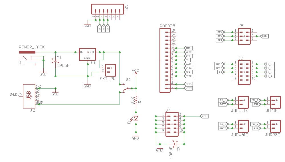
Below is the schematic diagram for the project. It includes the power supply, interface for LCD controller and text to speech module.
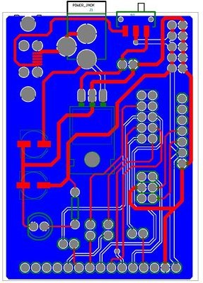
PCB Layout
Below is the PCB layout developed using Eagle PCB and Altium designer.
LCD display and RA8875 Driver Board
Hardware Interface
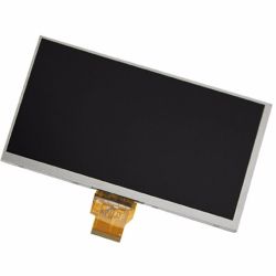
LCD Display
- This 7.0" TFT screen has 800x480 pixels, and an LED backlight.
- The display is supposed to be constantly refreshed, at 60Hz, with a pixel clock, V sync, H sync, etc.
- This display is operated by RA8875 Driver board.
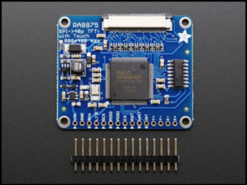
RA8875 Driver Board
RA8875 is a text/graphic mixed display with 2 layers TFT LCD controller which is a powerful and cheap choice for color display application. It is designed to meet the requirement of middle size TFT module up to 800x480 pixels with characters or 2D graphic application. Embedded 768KB display RAM provides user a flexible solution for display buffer of almost application. RA8875 supports a 2D Block Transfer Engine(BTE) that is compatible with 2D BitBLT function for processing the mass data transfer.
- Features:
- Support Text/Graphic Mixed Display Mode.
- Embedded 768KB DDRAM.
- Color Depth TFT: 256/65K Colors.
- Supporting TFT 8/16 bpp Generic RGB Interface.
- Powerful Block Scrolling Function for Vertical or Horizontal Direction.
Software Design
Flowchart
Code snippet
Wireless SJONE remote
Hardware Interface
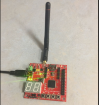
The wireless remote of the Snake and Ladder project is a slave device which always listen to commands send by the master node (console with fixed address of 100). It has one push button to control its operation and one LED to indicate the button presses. Any SJ one board with nordic wireless enabled with a unique address and the remote code flashed on it can join the game. All communication between master and remote are acknowledged.
- The operation of the remote can be abstracted to the below states:
- IDLE: When powered up, the resilient state of the remote is listening to instructions from a hard coded address 100. The pushbutton is inactive and just glows the LED when pressed. It is controlled via a semaphore given from the wireless command interpreter. The 7segment displays “0”.
- ENROLL: When an ‘enroll’ command broadcasted by the master console is received, the remote activates the pushbutton, giving the player the option to enroll in the game. If pushed, it will send a “enrollMe” information to the master. Note, that the remote does not keep track of the game start window and its upto the user to push the button to enrol in the game. If the user does not push the button, it will continue to stay in this same condition.
- STOP: The master sends the STOP command to indicate the end of a sequence of operation and to reset the remote to IDLE state. For example, after remotes are enrolled, the enrolment process is finished and remotes can go back to idle state till further instructions are given.
- PUSHED: The remote sends “pushed” information to the master when the button was activated by the master with a previous command (ie. a semaphore was given to the button task) and the user of the remote pressed the button. Note, its upto the master to interpret the meaning of this push in the context of previous command send.
- GO: The master sends ‘go’ command to a remote when it is that remotes turn to play. The command interpreter task would release a semaphore to the button task. As in the ENROLL state, its upto the user to press the button, if not pressed it will continue in the state. The 7segment will display “60” in this state.
- DICE: This is when a player pressed the button on his turn and received a dice roll count from the master. The value received is displayed on the 7segment. Note that to stay fair and impartial, the dice rolling is done at the console and not at the remote.
Software Design
FreeRTOS tasks handling the above operations:
The remote software has 3 tasks as below. The wireless command interpreter and game remote tasks communicate via FreeRTOS queues and the pushbutton task releases a semaphore to the game remote task based on the state of the remote.
- Wireless command interpreter: This task handles the wireless communication, interprets the commands received from master and passes stripped down messages to game remote task. This task is vaguely synonymous to a data link layer in OSI model.
- Game remote task: Handles all the remote states based on the queue messages received from wireless command interpreter task. It also waits for a semaphore from pushbutton task if the remote state is either ENROLL or GO. This task is synonymous the application layer in OSI model.
- Push button task: This is a free running task that monitor button presses and drives LED. If the remote is in either ENROLL or GO state, it releases a semaphore to the game remote task when a button is pressed.
Flowchart
Code snippet
Text to Speech Module
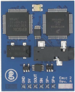
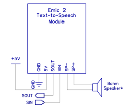
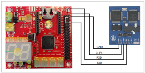
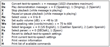
In Emic 2 Text-to-Speech(TTS) module we use UART protocol for communication with microcontroller. In this project, UART3 of the Sjone board is used for interface. This module has own commands for the text to speech conversion, voice selection, volume change.
- The pin configuration for Emic 2 TTS module is:
- SOUT – UART (RxD3)
- SIN – UART (TxD3)
- 5V – 3.3V (on board)
- GND - GND
- Its key features of Emic2 text-to-speech are as follows:
- High-quality speech synthesis for English and Spanish languages.
- Nine pre-defined voice styles comprising male, female, and child.
- Dynamic control of speech and voice characteristics, including pitch, speaking rate, and word emphasis.
- Industry-standard DEC talk text-to-speech synthesizer engine (5.0.E1).
- on board 3.5mm audio jack
Hardware Interface
Software Design
Algorithm:
- Initialize the emic2 TTS module to UART3.
- check function call for TTS module.
- Select text as per function call and play it on buzzer.
Flowchart
Code Snippet
Implementation
This section includes implementation, but again, not the details, just the high level. For example, you can list the steps it takes to communicate over a sensor, or the steps needed to write a page of memory onto SPI Flash. You can include sub-sections for each of your component implementation.
Testing & Technical Challenges
PCB
- Below is a list of challenges we faced during PCB designing:
- For designing the PCB, we use EAGLE software. Which is new for us and that was a challenging task to draw layout.
- We faced Assembly issues like dry solder on pins. So, we re-soldered the component pins.
- There was an insufficient bypassing on PCB hence we added required value of bypass capacitor on board.
- While testing PCB, we find a problem of shorting of a track so we use a multi meter to perform a continuity test and verification on the pins and fixed that.
LCD display
- The main challenged faced related to display is to print a snake and ladder picture grid. Also, to determine exact coordinates of snake and ladder on grid is one of the challenges. this a tough job but we manage to do that. Tried to achieved high refresh rate on LCD to get real time display effect.
Conclusion
We successfully completed our project of interactive snake and ladder by writing various modules and our mentioned overall objectives of it. We learned a lot about Sjone board and LPC1768 micro controller. we have added extra function in project so that multiple players (more than 2) can play the game simultaneously by just connecting antenna and flashing the code on SJone board. Hence this project increased our knowledge of software and hardware.
Project Video
Project Source Code
References
Acknowledgement
We would like to Thank Preetpal Kang. We used his API's of free RTOS which help us a lot to write a code for each module. The knowledge he has given us about all the interfacing buses like SPI, UART, I2C helped us in using that in our project and will help in near future.
References Used
List any references used in project.
Appendix
You can list the references you used.


