Difference between revisions of "S17: Smart security system"
Proj user13 (talk | contribs) (→PCB) |
Proj user13 (talk | contribs) (→PCB) |
||
| Line 133: | Line 133: | ||
First decision we had to make was what parts to use. Since we didn’t know fab companies are not soldering components, or charge extra for that, we created schematic with surface-mount components. After realising how small surface-mount components are and how difficult will be to solder them we had to start all over and change all components to through-hole. | First decision we had to make was what parts to use. Since we didn’t know fab companies are not soldering components, or charge extra for that, we created schematic with surface-mount components. After realising how small surface-mount components are and how difficult will be to solder them we had to start all over and change all components to through-hole. | ||
| + | |||
| + | Another important step was to choose library from which components will be imported. There is many library out there but we used [https://github.com/sparkfun/SparkFun-Eagle-Libraries sparkfun], [https://github.com/adafruit/Adafruit-Eagle-Library adafruit] and default Eagle library. | ||
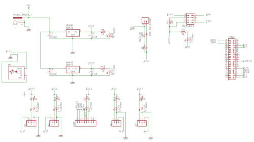
[[File:CMPE244 S17 SSS PSB schematics.png |500px|thumb|center|PCB Schematics]] | [[File:CMPE244 S17 SSS PSB schematics.png |500px|thumb|center|PCB Schematics]] | ||
| − | |||
We created a Board/Board Layout From Schematic also by following sparkfun tutorial [https://learn.sparkfun.com/tutorials/using-eagle-board-layout Using EAGLE: Board Layout]. One of the things that wasn’t well explained in this tutorial is how to create board with your specific dimensions. SInce our plan was to mount SJOne board above PCB it was important to make PCB with the same dimensions as SJOne board and more important, to have holes for standoffs at the same place as the one on SJOne board. Luckily there is “Dimension” tool we used for that, although it wasn’t so easy to delete the lines that are left after using that tool. | We created a Board/Board Layout From Schematic also by following sparkfun tutorial [https://learn.sparkfun.com/tutorials/using-eagle-board-layout Using EAGLE: Board Layout]. One of the things that wasn’t well explained in this tutorial is how to create board with your specific dimensions. SInce our plan was to mount SJOne board above PCB it was important to make PCB with the same dimensions as SJOne board and more important, to have holes for standoffs at the same place as the one on SJOne board. Luckily there is “Dimension” tool we used for that, although it wasn’t so easy to delete the lines that are left after using that tool. | ||
Revision as of 06:13, 11 May 2017
Contents
Grading Criteria
- How well is Software & Hardware Design described?
- How well can this report be used to reproduce this project?
- Code Quality
- Overall Report Quality:
- Software Block Diagrams
- Hardware Block Diagrams
- Schematic Quality
- Quality of technical challenges and solutions adopted.
Project Title
Abstract
This section should be a couple lines to describe what your project does.
Objectives & Introduction
Show list of your objectives. This section includes the high level details of your project. You can write about the various sensors or peripherals you used to get your project completed.
Team Members & Responsibilities
- Kayalvizhi Rajagopal
- Parth
- Purvil
- Miroslav
- SHubham
Project Schedule
| Sr. No. | Start Date | End Date | Task | Status | Actual Completion Date |
|---|---|---|---|---|---|
| 1 | 03/20/2017 | 03/26/2017 |
|
Completed | 03/26/2017 |
| 2 | 03/27/2017 | 04/02/2017 |
|
Completed | |
| 3 | 04/03/2017 | 04/09/2017 |
|
NCompleted | |
| 4 | 04/10/2017 | 04/16/2017 |
|
In Progress | |
| 5 | 04/17/2017 | 04/27/2017 |
|
Not started | |
| 6 | 04/28/2017 | 05/04/2017 |
|
Not started | |
| 7 | 05/05/2017 | 05/18/2017 |
|
Not started | |
| 8 | 05/19/2017 | 05/23/2017 |
|
Not started |
Parts List & Cost
Give a simple list of the cost of your project broken down by components. Do not write long stories here.
Design & Implementation
The design section can go over your hardware and software design. Organize this section using sub-sections that go over your design and implementation.
Hardware Design
Discuss your hardware design here. Show detailed schematics, and the interface here.
Hardware Interface
In this section, you can describe how your hardware communicates, such as which BUSes used. You can discuss your driver implementation here, such that the Software Design section is isolated to talk about high level workings rather than inner working of your project.
PCB
PCD design was created in Autodesk Eagle v8.1.0. But first we created a draft, on paper, with all parts and functionalities we wanted to put on our PCB. On sparkfun.com there is a great tutorial about how to create schematic in Eagle.
First decision we had to make was what parts to use. Since we didn’t know fab companies are not soldering components, or charge extra for that, we created schematic with surface-mount components. After realising how small surface-mount components are and how difficult will be to solder them we had to start all over and change all components to through-hole.
Another important step was to choose library from which components will be imported. There is many library out there but we used sparkfun, adafruit and default Eagle library.
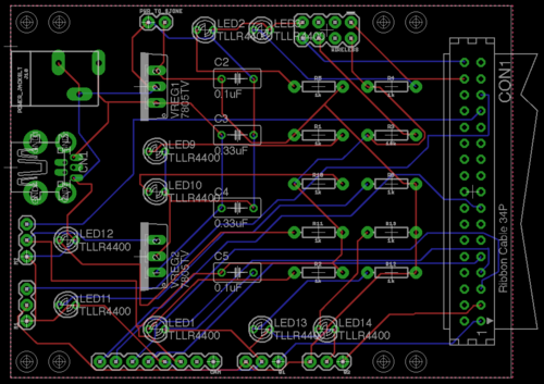
We created a Board/Board Layout From Schematic also by following sparkfun tutorial Using EAGLE: Board Layout. One of the things that wasn’t well explained in this tutorial is how to create board with your specific dimensions. SInce our plan was to mount SJOne board above PCB it was important to make PCB with the same dimensions as SJOne board and more important, to have holes for standoffs at the same place as the one on SJOne board. Luckily there is “Dimension” tool we used for that, although it wasn’t so easy to delete the lines that are left after using that tool.
After placing components where we wanted them, routing the board was easy with Autorouter...NOT. It produced too many errors, and wires were going too close to through-holes so we have to move wires away from them and basically do the routing manualy. Advice about routing would be to try to keep wires away as much as you can from through-holes, because when we were soldering components we were afraid that iron can damage the routes.
Checking for errors was maybe the most important part of whole process since it helped us detect and correct few errors which we didn’t see during layout. In order to check for errors tool “DRC” Design Rule Check is used. First we used sparkfun anddefault Eagle drc files to check for errors but after we decided which fab company to used, and after checking their website and guidelines we also did final check with their drc file, what is strongly recommended. Same goes with CAM file that helped us create gerber files recomended by fab houses.
Picking a PCB manufacturer was really easy after reading this analysis. We used Oshpark because of this sentence “The quality is excellent, the boards are produced domestically, and shipping is covered in your board price.” No need to say more….or actually there is...they are purple. Yes you read right, purple. It took less then 10 days to receive them from the day we submitted our request.
We already had many components we needed but the ones we didn’t have we had to buy. As the best choice, regarding the price, there is Excess Solution.
Software Design
Show your software design. For example, if you are designing an MP3 Player, show the tasks that you are using, and what they are doing at a high level. Do not show the details of the code. For example, do not show exact code, but you may show psuedocode and fragments of code. Keep in mind that you are showing DESIGN of your software, not the inner workings of it.
Implementation
This section includes implementation, but again, not the details, just the high level. For example, you can list the steps it takes to communicate over a sensor, or the steps needed to write a page of memory onto SPI Flash. You can include sub-sections for each of your component implementation.
Testing & Technical Challenges
Describe the challenges of your project. What advise would you give yourself or someone else if your project can be started from scratch again? Make a smooth transition to testing section and described what it took to test your project.
Include sub-sections that list out a problem and solution, such as:
My Issue #1
Discuss the issue and resolution.
Conclusion
Conclude your project here. You can recap your testing and problems. You should address the "so what" part here to indicate what you ultimately learnt from this project. How has this project increased your knowledge?
Project Video
Upload a video of your project and post the link here.
Project Source Code
References
Acknowledgement
Any acknowledgement that you may wish to provide can be included here.
References Used
List any references used in project.
Appendix
You can list the references you used.

