Difference between revisions of "F16: Object Detector"
(→Implementation) |
(→Team Members & Responsibilities) |
||
| Line 19: | Line 19: | ||
=== Team Members & Responsibilities === | === Team Members & Responsibilities === | ||
| + | TEAM 5 | ||
* Mohit Bhasin | * Mohit Bhasin | ||
** Make mount and configure Pixy Camera along with the SJOne Board | ** Make mount and configure Pixy Camera along with the SJOne Board | ||
| Line 26: | Line 27: | ||
**Design and Create Hardware connections between micro-controller and external parts. | **Design and Create Hardware connections between micro-controller and external parts. | ||
**Develop SPI Driver to allow for communication between the micro-controller and Pixy Camera | **Develop SPI Driver to allow for communication between the micro-controller and Pixy Camera | ||
| + | **Programmed pre-determined objects for Pixy to recognize | ||
== Schedule == | == Schedule == | ||
Latest revision as of 18:39, 21 December 2016
Contents
Abstract
Camera with object identifying abilities, to find a unique object as well as track it. Once the unique object is recognized by the Pixy Camera, the Camera will then lock the object's position. This will be done by the Pixy Camera sending a signal to the servos, to tell them where the object is within its frame. The microcontroller will then call a different function and control the servos to lock onto the object and track it as well. Overall, the main idea of this project is to create the drivers for the Pixy Camera to find the object and to communicate with the SJOne Board.
Objectives & Introduction
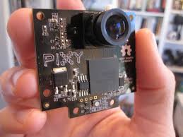
The objective of this project was to create a stand and interface for the Pixy Camera along with SJOne Board to lock onto and track a object. We found the Pixy Camera online, which is created by Charmed Labs, which they made to recognize the outlines of colorful object with certain signatures. We went ahead and created a stand, along with servos so the camera can interface with the microcontroller to control the camera to follow the object. This project has many purposes for tracking objects.
- 1. Gather information about Pixy Camera and its functionality.
- 2. Created pins diagrams to connect the servos, Pixy Camera and SJOne Board.
- 3. Create and buy parts for the stand and servos.
- 4. Assemble the parts and connect all the elements together.
- 5. Implment the SPI Interface between the Pixy Camera and SJOne Board.
- 6. Implement the servos with the Pixy Camera.
- 7. Test for a different types of functionality.
- 8. Make sure it locks and tracks the object with 180 degrees of range with Pan or Tilt.
Team Members & Responsibilities
TEAM 5
- Mohit Bhasin
- Make mount and configure Pixy Camera along with the SJOne Board
- Develop SPI Driver to allow for communication between the micro-controller and Pixy Camera
- Make communication between Pixy Camera and servos on the mount for movement
- Nadim Sarras
- Design and Create Hardware connections between micro-controller and external parts.
- Develop SPI Driver to allow for communication between the micro-controller and Pixy Camera
- Programmed pre-determined objects for Pixy to recognize
Schedule
A Table of our scheduled as planned before you started working on the project. Then in another table column, so the readers can see the planned vs. actual goals. The point of our schedule is for the readers to assess how to pace themselves if they are using our project as a reference or are doing something similar.
| Week# | Start Date | End Date | Task | Completion |
|---|---|---|---|---|
| 1 | 10/21/2016 | 10/28/2016 | Finish Proposal and confirm idea | Completed |
| 2 | 10/29/2016 | 11/04/2016 | Draw schematics of final product and determine the materials we need | Completed |
| 3 | 11/05/2016 | 11/11/2016 | Write Drivers for Pixy camera to learn and recognize objects | Completed |
| 4 | 11/12/2016 | 11/18/2016 | Make a mount for the camera that is able to move around and follow objects | Completed |
| 5 | 11/19/2016 | 11/25/2016 | Program Microcontroller to interface with the Pixy Camera, using SPI communication. | Completed |
| 6 | 11/26/2016 | 11/02/2016 | Finish Free RTOS tasks for the camera and movable mount | Completed |
| 7 | 12/03/2016 | 12/09/2016 | Test and Configure Project Accordingly | Completed |
| 8 | 12/10/2016 | 12/16/2016 | Final Tests | Completed |
Parts List & Cost
| Qty | Description | Manufacturer | Part Number | Cost | Links |
|---|---|---|---|---|---|
| 1 | SJ One Board [1] | Preet | SJ-one | $80 | http://www.socialledge.com/sjsu/index.php?title=SJ_One_Board |
| 1 | Pixy Camera | Amazon | CMUcam5 | $69 | https://www.amazon.com/Pixy-CMUcam5-Smart-Vision-Sensor/dp/B00IUYUA80 |
| 1 | Jumper Wires | Amazon | Jumper Wires | $8 | |
| 1 | Pan/Tilt Servo Motor Kit | Amazon | 2 Axis Robotic Camera Mount | $39 | https://www.amazon.com/gp/product/B00IVOEN1Y/ref=pd_sim_421_1?ie=UTF8&psc=1&refRID=A7PW5YB91E29JTAEV4TP |
Design & Implementation
Within the Design & Implementation section, we have included both the hardware design as well as the software design. We used a Pixy Camera and communicated with through UART protocol. We also show how we assembled and created the mount, so the camera can move. The software section includes the logical flow and a diagram of our algorithm.
Hardware Design
We have included detailed hardware schematics and the interface of each component.
Pixy Camera
The Pixy Camera uses a color-based filtering algorithm to detect objects. Pixy can easily connect to lots of different controllers because it supports several interface options, like UART communication that is being used for the project. The information that is being sent out from the Pixy Camera to the SJOneBoard is the sync word (0xaa55), checksum (sum of all 16-bit words 2-6), signature number, x center of object, y center of object, width of object, height of object. All this information lets us know where the object is in frame, how big it is and the color as well.
Pixy Camera Mount
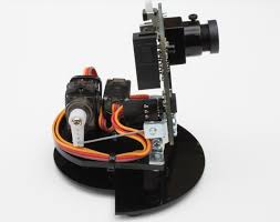
The Pixy Camera Mount was made so the camera had a place to sit on. The mount is very useful when testing or using this camera, because then no one has to hold the camera while using it. Instead the camera can rest on the mount which can be placed anywhere and allows easy access to the camera. This way the camera also has the ability to move left - right and up - down.
PWM Servos
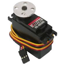
Pulse With Modulation Servos are useful for this project, since they allow the camera to move left - right and up - down. Pulse width modulation allows us to vary how much time the signal is high in an analog and this lets us control how the servo moves. With a pulse in the middle, the servo motor will rest at 90 degrees. With the low pulse, the servo will be at the 0 degree and with a large pulse, the servo will be at 180 degrees. Once we receive information from the Pixy Camera we can then modify the position of the servos to move along with the object.
SJOneBoard
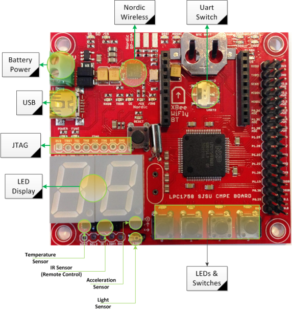
The SJOneBoard is used as the brains of the project. It communicates with the Camera and is able to receive data about the object. The SJOneBoard also powers the Camera. It is also used to send signals to camera to use the servo motors on the camera, so they can move and follow the object.
Hardware Interface
In this section, we describe how our hardware communicates, such as which driver implementation we used on a high level workings of our project.
To communicate with SJOneBoard and the Pixy Camera we are using a UART communication driver. This allows us to transmit bits to the Pixy Camera so we can receive useful bits back from the camera. Once we are able to figure out where the object is within the frame and where it is moving, we can trasmit useful bits back to the Pixy Camera. Since there are servos attached onto the Pixy Camera and its mount, we can use these to move the camera around to follow an object. If the object goes out of frame the Pixy can move around until it finds it or turn an LED on saying that it cannot find the object.
Software Design SJOne Board
The SJOne board utilizes a UART task in order to communicate with the Pixy Camera. The driver task consists of initializing the registers of the SJOne Board, receiving and sending bytes of information. Below is the Pseudocode an explanation for each function utilized within the UART driver.
The corresponding UART port must be initialized by powering on the PCONP register. The peripheral clock must then be set to the corresponding value of the peripheral device. In order for the UART transfer to take place the SJOne board utilizes the Tx and Rx pins which are also set within the initialization block by using the PINSEL Register to program the functionality. The Baud Rate must match the Pixy Camera Baud Rate of 19200bps. This was set utilizing the equation below. From this equation we derive the DLL and DLM registers which are used as the divisors to establish the desired baud rate for the data transfer. The DLAB bit must also be initialized at is used as both the Receiver Buffer Register and the Transmit Holding Register. Both of which are set at the LCR register. The LCR register is also responsible for setting the start and stop bits of the UART communication.
Initialization PseudoCode
 PCONP = Power on UART2
 PCLKSEL1 = Set Peripheral Clock
 PINSEL4 = Set RX and TX pin functionalities
 // Acquire DLL_Value from desired Baud Rate
 DLL_Value = clock/(16*Baud)
 Set DLM and DLL registers according to DLL_Value
 LCR = Set 8 bit data transfer Length
 LCR = Set start and stop bit for data transfer
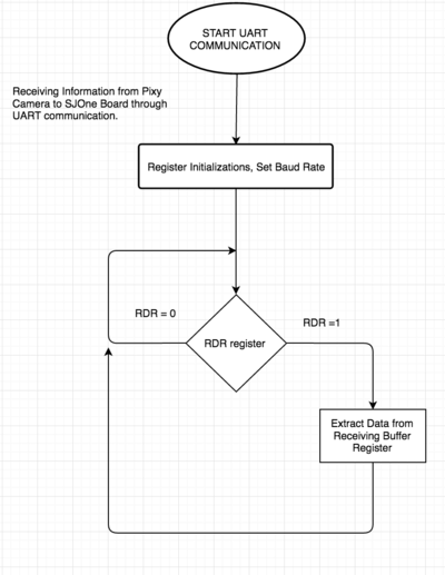
Since the SJOne board is only receiving data from the Pixy Camera and not sending data in this situation only a receive byte function is required. The function waits to see if the data is transmitted from the Pixy Camera to the SJOne board by checking the RDR (Receiver Data Ready) register. Once the value of this register is set to 1, the receive function can then capture the transmitted data by looking at the RBR (Receiver Buffer Register).
Receiving Function PseudoCode
  while (1){
       if(RDR){
        break;
       }
  }
  new_data = RBR;
Pixy Camera Software Implementation
The Pixy Camera is able to externally communicate with micro-controllers by sending data regarding the object it is tracking, as well as receiving data for controlling the Pixy Camera itself. When the Pixy camera locates a recognized or preprogrammed object it begins to send information to a connected peripheral in bytes regarding that object. The first few bytes the Pixy camera sends are sync bytes, in other words bytes that let the external device know that the Pixy Camera has picked up on an object. The rest of the following bytes indicate the signature of the object, where it is on the screen with respect to the camera view (x/y center), as well as the width and the height of the object. Below are the specific bytes the Pixy Camera send to the SJOne board when it picks up on a device.
The SJOne board is also able to control information to the Pixy Camera in order to control the pan and tilt of the servos, LED color, and camera brightness. However, the pan and tilt byte information is our area of concern with respect to control information being sent to the Pixy Camera. If the correct bytes are sent then the SJOne board acts as a master driving the pan and tilt servos of the Pixy Camera.
Implementation
Initially, the Pixy Camera is programmed to recognize a specific object that appears into its view. The UART hardware connections are then made between the Pixy Camera and the SJOne board. The SJOne board registers are initialized and the baud rate is set to match the baud rate of the Pixy Camera. The task then continuously runs the read function in order to continuously grab data from the Pixy Camera. The SJOne board then continuously checks to see if the received data from the Pixy Camera matches the sync byte 0xaa55. This tells the SJOne board that the camera has picked up on an object. Once this byte is received the following bytes will include information regarding the recognized object. Below is the flow of the UART communication, as well as the Pseudo Code behind the implementation.
Implementation Pseudo Code
 init(Baud_Rate); // initialize Baud Rate and UART registers
 while(1){
    data_byte1 = read_byte();
    data_byte2 = read_byte();
    if (data_byte1 & data_byte2 == 0xaa55){     // 0xaa55 means Pixy has recognized the object and the following 12bytes sent will describe that object.
      for (i < 11) // Allows the following 12 bytes of object information to be grabbed
      grab_object_data = read_byte();
   }
 }
Once the data is retrieved from the SJOne board, an application was added to where the SJOne board would be able to identify objects based on the bytes it had received from the Pixy Camera. Utilizing this application the SJOne board was able to recognize a pair of green scissors, an orange, and a blue box.
Testing & Technical Challenges
We had a couple of technical challenges while we testing our project. In this section we shall describe the challenges of our project. We will also advise the readers if our project can be started from scratch again or they are trying to achieve similar results.
Testing
We tested our project in different in parts. First we had tested the UART communication of the SJOneBoard with another SJOneBoard to see if the UART protocol was working properly. Once we were successfully able to transmit and receive bits, we moved onto the next step. Although the driver for UART is already written we have to make changes for the purpose of our project. We made another RTOS Task for the new UART for communication with the Pixy and the Pixy's servos. Once we completed this we tested to see if we could properly read the bits from Pixy Camera through UART interface. We used a Saleae to see the bits that were being transferred. Then we could control the servos on the Pixy once we received the correct information. We used test cases with one object and then we moved to two objects for the purpose of this project. We noticed it could see all the objects, but could only track one, which would be the most sensitive object.
My Issue #1
Establishing communication between the Pixy Camera and the SJOne micro-controller proved to be the most difficult task. The Pixy Camera micro-controller was configured and manufactured for Arduino capabilities. However no one has ever established communication between the Pixy Camera and the SJOne board before. The team initially attempted to establish a SPI interface between the Pixy Camera and the SJOne board. However, after multiple failed attempts, most likely caused by the different clock rates, the team then switched over to UART communication.
My Issue #2
Another issue we ran into was to gain access to utilize the Pixy's servo controls. Since we have attached two servos on the back of the camera and mounted to the mount. We want to control them so we can move the Pixy camera to follow the object. Apparently you have to send certain bytes to tell the Pixy you want to gain access to its servo controls. Then we have to send the bytes to tell the Pixy how to pulse the servos, so they are in the positions we want them to be in.
Conclusion
In conclusion, we were able to complete necessary for our project. All though we done what was needed, we believe that it isn't enough and we could've have done more. When we were testing we ran into problems like every other group, but we able to navigate past them successfully. We are glad we took this Embedded Systems class, because we able to learn how FREE RTOS operating system works and how we can implement it for our project. We have also learned how to implement different types of communication protocols and how to program their drivers. The main part we learned from this project is to make sure to set a team leader and make sure people follow their lead to finish the tasks. Within a group project, you have to hold your teammates accountable, make sure you set deadlines, make sure people are getting their work done and this is pretty important in real work place situations.
Project Video
We have uploaded the video onto YouTube and the link below will allow you access to the video.
Project Source Code
https://github.com/nsarras/Object_Detector
References
Acknowledgement
Professors
- Preet
- Dr Ozemek
Lab Assistants
- Praveen Prabhakaran
- Shilpa Srinivasan
References Used
List any references used in project.

