Difference between revisions of "F16: E-Bike"
146 user13 (talk | contribs) (→Hardware Interface) |
146 user13 (talk | contribs) (→Hardware Interface) |
||
| Line 247: | Line 247: | ||
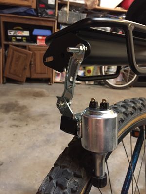
[[File:CmpE146_F16_Generator.jpg|400|px|thumb|left|Figure #. Generator]] <br> | [[File:CmpE146_F16_Generator.jpg|400|px|thumb|left|Figure #. Generator]] <br> | ||
| + | |||
| + | |||
| + | |||
| + | |||
| + | |||
| + | |||
| + | |||
| + | |||
| + | |||
Revision as of 07:46, 20 December 2016
Contents
Grading Criteria
- How well is Software & Hardware Design described?
- How well can this report be used to reproduce this project?
- Code Quality
- Overall Report Quality:
- Software Block Diagrams
- Hardware Block Diagrams
- Schematic Quality
- Quality of technical challenges and solutions adopted.
E-Bike
Abstract
Electrics bicycles are the future of transportation. Our project helps build on this future by advancing electric bike design. We have two motors on the bike. One generates power to charge an on-board battery, while the other propels the bike forward as requested by user input. This allows the user to reach steady transportation speeds without the need to pedal constantly. A more effective future of transportation based on renewable energy is the way forward for us and the planet.
Objectives & Introduction
Show list of your objectives. This section includes the high level details of your project. You can write about the various sensors or peripherals you used to get your project completed.
1. Allow a motor to propel a bike forward when a button is pressed
2. Create a battery driven power circuit that can support an embedded system and can be charged without a wall adapter
3. Show the user the current status of their battery
Team Members & Responsibilities
- Nicholas Randhawa
- Power circuit
- A/D Converter
- Alejandro Puente
- Display battery level to external screen over UART
- Shared Responsibilities
- Hardware mounting
- GPIO drivers
- RTOS tasks to integrate everything
Schedule
| Week # | Proposed Completion Date | Task | Status | Actual Completion Date |
|---|---|---|---|---|
| 1 | 10/28 | Finalize project idea and determine hardware requirements | Completed | 10/28 |
| 2 | 11/04 | Order parts | Completed | 11/04 |
| 3 | 11/11 | Draw schematics | Completed | 11/11 |
| 4 | 11/18 | Get A/D on LPC working
Output reading to an external screen |
Completed | 11/18 (A/D)
12/06 (Screen) |
| 5 | 11/25 | Get MOSFETs working with motors
Finalize power circuit build |
Completed | 12/17 |
| 6 | 12/02 | Create RTOS tasks to integrate A/D with the MOSFETs | Completed | 11/29 |
| 7 | 12/09 | Mount hardware and begin testing | Completed | 12/18 |
| 8 | 12/16 | Fix defects, finish report, and clean up code | Completed | 12/19 |
Parts List & Cost
Give a simple list of the cost of your project broken down by components. Do not write long stories here.
| Part # | Part Name | Quantity | Cost ($) per 1 part |
|---|---|---|---|
| 1 | Bike | 1 | Free |
| 2 | LCD Screen | 1 | 11 |
| 3 | 36V, 10Ah Rechargable Battery | 1 | 250 |
| 4 | Push Button | 1 | 0.93 |
| 5 | Speed Controller | 1 | 10 |
| 6 | SJOne Board | 1 | 80 |
| 7 | Circuit Case | 1 | 8 |
| 8 | Screen and controller case | 1 | Free |
| 9 | High Power MOSFET | 2 | 4 |
| 10 | 250W DC Motor | 1 | 50 |
| 11 | 50W AC Generator | 1 | 30 |
| 12 | Boost Converter | 1 | 10 |
| 13 | Buck Converter | 1 | 9 |
| 14 | Terminal Block | 2 | 0.70 |
| 15 | Resistors | 6 | 0.10 |
| 16 | Rectifying Diodes | 7 | 0.10 |
| 17 | Plastic Standoffs | 16 | 0.10 |
| 18 | Small PCB | 1 | 1 |
| 19 | 8mm Motor Arbor Adapter | 1 | 8 |
| 20 | Skateboard Wheel | 1 | Free |
| 21 | Bike Rack | 1 | 14 |
| 22 | Zipties | 14 | 0.4 |
| 23 | Bungee Cord | 3 | 0.90 |
Design & Implementation
The design section can go over your hardware and software design. Organize this section using sub-sections that go over your design and implementation.
Hardware Design
Discuss your hardware design here. Show detailed schematics, and the interface here.
Figure ##: High level view of the major hardware components on the bike
The figure above shows a high level view of our system on the bike. We have the generator sending power to the main circuit to be rerouted to the battery when needed, the battery getting power from the main circuit and providing power to the circuit, the motor getting power from the circuit, the push button and speed controller on the handlebars sending feedback to the circuit based on user input, and the screen on the handlebars getting data from the circuit.
Figure ##: Circuit schematic of our e-bike
Our hardware design consists of four major sections. The first section of the circuit is the generator which is in yellow on the diagram. Our generator design is driven by a 50W AC generator. It feeds varying voltage to a bridge rectifier circuit to smooth out the signal before going into a boost converter. The boost converter takes the 12-20V input and puts out a steady 42V at 2A. Our boost converter output goes to a MOSFET transistor. This transistor is controlled by a GPIO driver on the SJOne Board. When we want to charge, the MOSFET activates and sends the 42V, 2A electrical energy to the on-board battery. The on-board battery is the heart of our system. It is a 36V, 10Ah lithium polymer battery. Our battery is also the key component for our next major circuit section; the power circuit.
The power circuit sends power to 3 different locations; the ADC, the motor, and the SJOne Board. Starting with the ADC, we are utilizing a voltage divider circuit to step down the voltage to safe, operating levels for the LPC CPU on the SJOne Board. We are using the overcharge voltage of the battery with the ADC to measure how much juice is left in the battery for the user. Next, the power is sent to a buck converter. The buck converter steps down the voltage to the operating 5V that the microcontroller needs to operate. Finally, the battery sends power to the motor.
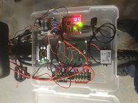
The SJOne Board is the key component in our next major circuit section which is the microcontroller in green. If the battery is the heart of the system, the microcontroller is the brain. We have it attached to 2 MOSFETs so it can control when we want to charge the battery or use energy to activate the electric bike motor. A user requests motor output through a different GPIO port from an on-board button on the handlebars. When the button is pressed, the SJOne Board will activate the motor MOSFET and the bike will be propelled forward with less pedaling required. The speed of the motor is controlled by a speed controller also on the handlebars. It is basically just a knob that can change the motor speed from zero to max, or 0A to 7A. Finally, the microcontroller contributes to the other major section which is the output of our system.
One of the output components is the motor mentioned already, and the other component is the screen on the handlebars. In addition to the output mentioned for the motor, we have a diode across it to protect our system from any spikes in current that might occur when starting and stopping the motor. Our other output, the screen, displays the battery level so a user knows how much juice they have left. The screen is the best way for our user to know what's going on with the system at any moment.
Hardware Interface
In this section, you can describe how your hardware communicates, such as which BUSes used. You can discuss your driver implementation here, such that the Software Design section is isolated to talk about high level workings rather than inner working of your project.
ADC
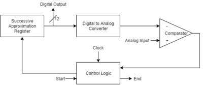
Figure ##: Overview of the successive approximation ADC that the LCP1768 utilizes
The ADC interface utilizes the on-board 12-bit ADC built into the LPC1768 CPU. We needed to understand the pins, registers, and how they worked to give a digital voltage reading. The CPU uses a 12-bit successive approximation register to get the reading of the analog voltage as displayed in the diagram above. The max operating voltage it can read is 3.3V since that is also its reference voltage. With this in mind, we knew we had a sample size of 0.8mv which was accurate for our needs. After figuring all this out, following the manual for the driver and for actually computing information was easy. We are using a voltage dividing circuit to measure the overcharge voltage of the battery according to the table below. The overcharge voltage is sent to an ADC channel on the CPU (we had 8 different ones to choose from), and the voltage we read there gives us a percentage that can be calculated based on the known maximum value.
Table 1: Overcharge Voltage Chart Readings
| Overcharge Voltage (V) | Battery Pct (%) |
|---|---|
| 42.0 | 100 |
| 41.4 | 90 |
| 40.8 | 80 |
| 40.2 | 70 |
| 39.6 | 60 |
| 39.0 | 50 |
| 38.4 | 40 |
| 37.8 | 30 |
| 37.2 | 20 |
| 36.6 | 10 |
| 36.0 | 0 |
UART
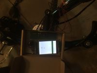
The screen on our e-bike utilizes the UART communication bus. In particular, we are using UART2 from the LPC1768 CPU. The details of the driver code and communication are given in the software section below. For the hardware interface, it's important to note that our screen's RX and TX complement the board's, and both devices share a common ground.
GPIO
The general purpose input and output ports in our system play a very important role in the orchestration of current when charging the battery and activating the motor. We have an input port set to receive information from the push button on the handlebars. Once data is received, we use a general output port to activate a MOSFET controlling a motor if power is available to start spinning the front wheel. In terms of charging, we use the information from the ADC to determine when to send a high signal out of another general purpose output port. This high signal activates a different MOSFET that will allow charging current to flow into the battery.
Software Design
Show your software design. For example, if you are designing an MP3 Player, show the tasks that you are using, and what they are doing at a high level. Do not show the details of the code. For example, do not show exact code, but you may show psuedocode and fragments of code. Keep in mind that you are showing DESIGN of your software, not the inner workings of it.
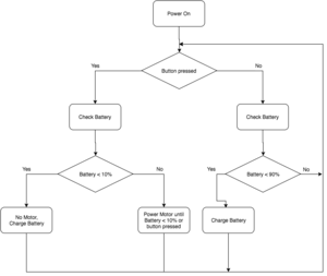
The software communication we have created different tasks and functions to handle different events. The way we send data from the board to the screen is shown below in psuedocode:
void uart2_init(uint32_t baud) {
       clear p2.8 for txd2 and p2.9 for rxd2
       set p2.8 as txd2 and p2.9 for rxd2

       clear uart2 clock
       enable uart2 clock
       set data size as byte
       enable DLAB bit
       calculate speed value
       disable DLAB bit
}
void uart2_putchar(char out) {
    Store data in buffer
    while(1) {
     if (LPC_UART2->LSR & (1 << 5)) // wait until data is sent
     break;
   }
}
void uart2_end() {
uart2_putchar(0xFF); send this 3 times to let screen know we are done sending info
}
Implementation
- Communication between the board and battery
- The battery talks to the board through the ADC.
- Communication between the board and the LCD screen:
- This was done with UART communication. Sending single bytes to update the screen to reflect the proper level of battery remaining.
This section includes implementation, but again, not the details, just the high level. For example, you can list the steps it takes to communicate over a sensor, or the steps needed to write a page of memory onto SPI Flash. You can include sub-sections for each of your component implementation.
Testing & Technical Challenges
Describe the challenges of your project. What advise would you give yourself or someone else if your project can be started from scratch again? Make a smooth transition to testing section and described what it took to test your project.
Include sub-sections that list out a problem and solution, such as:
Software Challenges
- LCD screen
- It came with the wrong instructions
Hardware Challenges
- Mounting the motor to the frame
- When it came to mounting the motor to the frame, we ran into a couple of issues. We couldn't figure out how to attach the motor to the frame so that there was enough tension for it to drive the front tire. We decided to rotate the motor 90 degrees and use a bolt to attach it to the frame and some Zip ties to keep it from rotating when driving the tire.
- Back Bicycle rack kept shifting
- When we installed the rack behind the seat we didn't realize the size of the circumference was too big around the seat pole so it kept rotating. Tightening it didn't help. We needed the rack to be stable because that's where our circuit goes, so we decided to add zip ties to it to keep it from rotating.
- MOSFET Overheating
- We ran into an issue once we had everything wired up. We realized once the motor was
Conclusion
Conclude your project here. You can recap your testing and problems. You should address the "so what" part here to indicate what you ultimately learnt from this project. How has this project increased your knowledge?
Project Video
Project Source Code
References
Acknowledgement
We'd like to thank the Academy.
Bob from Home Depot
References Used
List any references used in project.
Appendix
You can list the references you used.


