Difference between revisions of "F16: Thunderbolt"
Proj user14 (talk | contribs) (→Compass Module) |
Proj user14 (talk | contribs) (→Compass Module) |
||
| Line 1,022: | Line 1,022: | ||
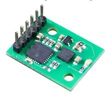
The Compass Module we use in our project is ''CMPS11 - Tilt Compensated Compass Module''. It employs a 3-axis magnetometer, 3-axis gyro and a 3-axis accelerometer. A Kalman filter is used to combine the gyro and accelerometer to remove the errors caused by tilting of the PCB. The output of the three sensors measuring x, y and z components of the magnetic field, together with the pitch and roll are used to calculate the bearing. It requires a power supply of 3.6-5V. The module can be operated in two modes - serial or I2C. <br> | The Compass Module we use in our project is ''CMPS11 - Tilt Compensated Compass Module''. It employs a 3-axis magnetometer, 3-axis gyro and a 3-axis accelerometer. A Kalman filter is used to combine the gyro and accelerometer to remove the errors caused by tilting of the PCB. The output of the three sensors measuring x, y and z components of the magnetic field, together with the pitch and roll are used to calculate the bearing. It requires a power supply of 3.6-5V. The module can be operated in two modes - serial or I2C. <br> | ||
| − | |||
| − | |||
[[File: CmpE243_F16_Thunderbolt_Compass_Module.JPG|right|220px|thumb|Compass Module ]] | [[File: CmpE243_F16_Thunderbolt_Compass_Module.JPG|right|220px|thumb|Compass Module ]] | ||
Revision as of 09:57, 10 December 2016
Contents
- 1 Project Title
- 2 Abstract
- 3 Objectives & Introduction
- 4 Team Schedule
- 5 Team members and Responsibilities
- 6 Parts List & Cost
- 7 DBC File
- 8 Master Controller
- 9 Sensor Controller
- 10 Motor & I/O Controller
- 11 Geographical Controller
- 12 Android and Communication Bridge Controller
- 13 Conclusion
- 14 References
Project Title
Thunderbolt - a self driving RC car
Abstract
This section should be a couple lines to describe what your project does.
Objectives & Introduction
Show list of your objectives. This section includes the high level details of your project. You can write about the various sensors or peripherals you used to get your project completed.
Team Schedule
Color Legends :
- Common to all modules
- Master Controller
- Motor Controller
- Sensor Controller
- Geographical Controller
- Communication Bridge
| Sr No | Start Date | End Date | Task | Status | Problems/Delays if any |
|---|---|---|---|---|---|
| 1 | 09/14/2016 | 09/20/2016 |
|
Completed | |
| 2 | 09/21/2016 | 09/27/2016 |
|
Completed | |
| 3 | 09/28/2016 | 10/04/2016 |
|
Completed | |
| 4 | 10/05/2016 | 10/11/2016 |
|
Completed | |
| 5 | 10/12/2016 | 10/18/2016 |
|
Completed | |
| 6 | 10/19/2016 | 10/25/2016 |
|
Completed | |
| 7 | 10/26/2016 | 11/01/2016 |
|
Completed | |
| 8 | 11/02/2016 | 11/08/2016 |
|
Completed | Compass Calibration is ongoing |
| 9 | 11/09/2016 | 11/15/2016 |
|
In Progress | |
| 10 | 11/16/2016 | 11/22/2016 |
|
||
| 11 | 11/23/2016 | 11/29/2016 |
|
||
| 12 | 11/30/2016 | 12/06/2016 |
|
||
| 13 | 12/07/2016 | 12/13/2016 |
|
Team members and Responsibilities
- Master Controller
- Abhishek Singh
- Saurabh Ravindra Deshmukh
- Neha Biradar
- Motor Controller
- Krishank Mehta
- Neha Biradar
- Saurabh Ravindra Deshmukh
- GPS/Compass Module
- Samiksha Ambekar
- Virginia Menezes
- Sensors
- Arthur Nguyen
- Rajeev Sawant
- Samiksha Ambekar
- Bluetooth
- Abhishek Singh
- Nikhil Namjoshi
- Android Application
- Nikhil Namjoshi
- Saurabh Ravindra Deshmukh
Parts List & Cost
| Item# | Part Desciption | Vendor | Datasheet | Qty | Cost |
|---|---|---|---|---|---|
| 1 | RC Car | from Preet | 1 | ||
| 2 | CAN Transceivers MCP2551-I/P | Microchip [1] | MCP2551-I/P Datasheet [2] | 8 | Free Samples |
| 3 | Sonar Sensor | Amazon [3] | Maxbotix EZ1 MB 1010 Datasheet [4] | 4 | $24.95 |
| 4 | GPS with SMA Connector | SparkFun [5] | Venus638FLPx Datasheet [6] | 1 | $49.95 |
| 5 | Compass (CMPS11) | Acroname [7] | 1 | $45.95 | |
| 6 | Antenna GPS Embedded SMA | Sparkfun [8] | 1 | $11.95 | |
| 7 | Bluetooth to Serial Port Module HC-05 | Gearbest.com [9] | 1 | $3.25 | |
| 8 | Magnets | Amazon.com [10] | 1 | $4.56 |
DBC File
The DBC file implementation can be accessed at the following link:
https://gitlab.com/singh.abhishek21/Thunderbolt_CMPE243/blob/master/243.dbc
CAN Communication Table
| Sr. No | Message ID | Message function | Message Data | From | To |
|---|---|---|---|---|---|
| High | |||||
| 1 | 0x148 | Communication bridge ( | |||
Master Controller
Schedule
| Sr No | Start Date | End Date | Task | Status | Actual Completed Date |
|---|---|---|---|---|---|
| 1 | 10/12/2016 | 10/18/2016 |
|
Completed | |
| 2 | 10/19/2016 | 10/25/2016 |
|
Completed | |
| 3 | 10/25/2016 | 11/01/2016 |
|
Completed | |
| 4 | 11/02/2016 | 11/08/2016 |
|
In Progress | |
| 5 | 11/09/2016 | 11/15/2016 |
|
||
| 6 | 11/16/2016 | 11/22/2016 |
|
||
| 7 | 11/23/2016 | 11/29/2016 |
|
||
| 8 | 11/30/2016 | 12/06/2016 |
|
||
| 9 | 12/07/2016 | 12/13/2016 |
|
Design & Implementation
The design section can go over your hardware and software design. Organize this section using sub-sections that go over your design and implementation.
Hardware Design
Discuss your hardware design here. Show detailed schematics, and the interface here.
Hardware Interface
In this section, you can describe how your hardware communicates, such as which Buses used. You can discuss your driver implementation here, such that the Software Design section is isolated to talk about high level workings rather than inner working of your project.
Software Design
Show your software design. For example, if you are designing an MP3 Player, show the tasks that you are using, and what they are doing at a high level. Do not show the details of the code. For example, do not show exact code, but you may show psuedocode and fragments of code. Keep in mind that you are showing DESIGN of your software, not the inner workings of it.
Implementation
This section includes implementation, but again, not the details, just the high level. For example, you can list the steps it takes to communicate over a sensor, or the steps needed to write a page of memory onto SPI Flash. You can include sub-sections for each of your component implementation.
Testing & Technical Challenges
Describe the challenges of your project. What advise would you give yourself or someone else if your project can be started from scratch again? Make a smooth transition to testing section and described what it took to test your project.
Sensor Controller
Group Members
- Arthur Nguyen
- Rajeev Sawant
Schedule
| Sr No | Start Date | End Date | Task | Status | Actual Completion Date |
|---|---|---|---|---|---|
| 1 | 10/05/2016 | 10/11/2016 |
|
Complete | 10/11/2016 |
| 2 | 10/12/2016 | 10/18/2016 |
|
Complete | 10/18/2016 |
| 3 | 10/19/2016 | 10/25/2016 |
|
Complete | 10/25/2016 |
| 4 | 10/26/2016 | 11/01/2016 |
|
Complete | 11/01/2016 |
| 5 | 11/02/2016 | 11/08/2016 |
|
Complete | |
| 6 | 11/09/2016 | 11/15/2016 |
|
||
| 7 | 11/16/2016 | 11/22/2016 |
|
||
| 8 | 11/23/2016 | 11/29/2016 |
|
||
| 8 | 11/30/2016 | 12/06/2016 |
|
Design & Implementation
The design section can go over your hardware and software design. Organize this section using sub-sections that go over your design and implementation.
Hardware Design
The sensor controller is the crux of the obstacle avoidance algorithm of the car.
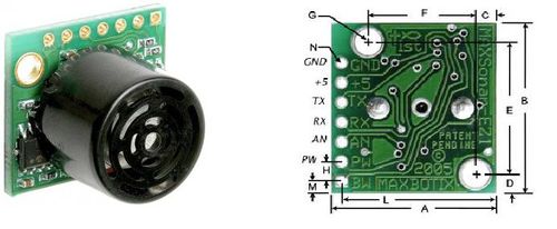
It consists of four ultrasonic sensors connected to the LPC1758 board. We have used the MaxSonar MB1010 sensor as it provides a good balance between sensitivity and object rejection. Three of the sensors (left, center and right) are placed in the front and one sensor is positioned at the back.
Hardware Interface
In this section, you can describe how your hardware communicates, such as which BUSes used. You can discuss your driver implementation here, such that the Software Design section is isolated to talk about high level workings rather than inner working of your project.
MaxSonar MB1010 Sensor
Software Design
Show your software design. For example, if you are designing an MP3 Player, show the tasks that you are using, and what they are doing at a high level. Do not show the details of the code. For example, do not show exact code, but you may show psuedocode and fragments of code. Keep in mind that you are showing DESIGN of your software, not the inner workings of it.
Implementation
This section includes implementation, but again, not the details, just the high level. For example, you can list the steps it takes to communicate over a sensor, or the steps needed to write a page of memory onto SPI Flash. You can include sub-sections for each of your component implementation.
Testing & Technical Challenges
Describe the challenges of your project. What advise would you give yourself or someone else if your project can be started from scratch again? Make a smooth transition to testing section and described what it took to test your project.
1. Delay time of RX
2. Angle of sonar sensors
Motor & I/O Controller
Group Members
- Krishank Mehta
- Saurabh Deshmukh
- Neha Biradar
Schedule
| Sr No | Start Date | End Date | Task | Status | Actual Completed Date | Problems Encountered if any |
|---|---|---|---|---|---|---|
| 1 | 9/19/2016 | 9/27/2016 |
|
Completed | 9/25/2016 | |
| 2 | 9/28/2016 | 10/4/2016 |
|
Completed | 10/5/2016 | |
| 3 | 10/7/2016 | 10/10/2016 |
|
Completed | 10/10/2016 | Problem with finding the starting pwm pattern for DC Motor |
| 4 | 10/11/2016 | 10/18/2016 |
|
Completed | 10/17/2016 | |
| 5 | 10/20/2016 | 10/24/2016 |
|
In progress | ||
| 6 | 10/26/2016 | 10/28/2016 |
|
Completed | 11/26/2016 | |
| 7 | 11/01/2016 | 11/08/2016 |
|
In progress | ||
| 8 | 11/15/2016 | 11/18/2016 |
|
Completed | 11/7/2016 | |
| 9 | 11/18/2016 | 11/22/2016 |
|
In progress |
Design & Implementation
The design section can go over your hardware and software design. Organize this section using sub-sections that go over your design and implementation.
Hardware Design
Motor Module
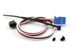
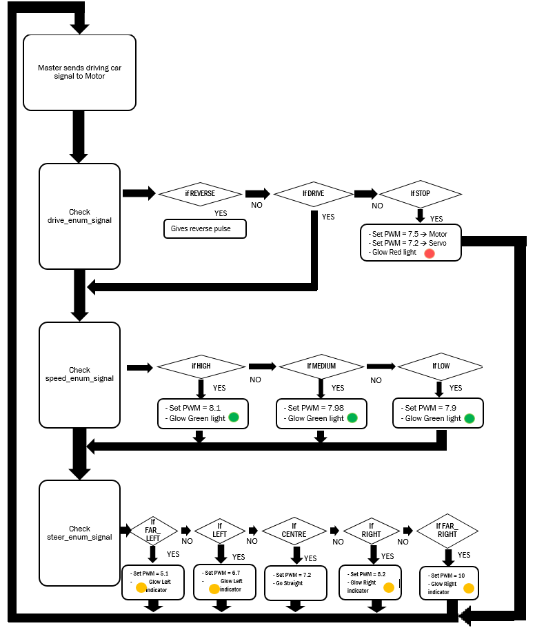
The Motor module consists of servo motor, DC motor and speed sensor module. The servo motor is responsible for steering of the car and the DC motor is responsible for speed control.
The Master controller sends signals of drive, speed and steer to the motor controller to navigate the car, based on the information received from Sensors and GPS.
DC Motor
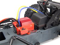
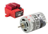
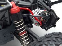
In the car, we have the ARRMA MEGA waterproof 35A ESC, combined with the 15T MEGA Brushed Motor.
The MEGA ESC is designed to be used with the supplied NiMh Battery Pack and can easily handle 2S LiPo battery packs or 7 cell 8.4V NiMh battery packs.
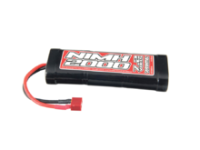
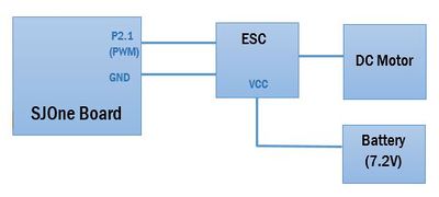
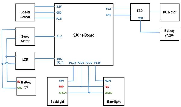
The ESC (Electronic Speed Control) is connected to the SJOne board to generate the PWM as shown in the block diagram below, which is connected to the DC Motor. It is powered by a ARRMA 6 Cell 2000mAh 7.2 volt NiMh Battery.
Servo Motor
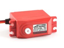
The Servo motor in our car is ADS-5 Steering Servo, which will provide fast and consistent steering response on the most demanding surfaces. This servo provides 5kg/cm (70oz/inch) of torque.
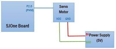
The servo motor is connected to the SJOne board and provided PWM signal to control the steering of the car in 5 directions - far left, left, center, right, far right.
Speed Sensor
IO Module
The IO Module consists of a LCD Module and backlights based on the direction and movement of the car.
LCD Display
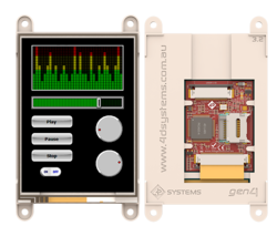
The LCD Module we are using in the project is a gen4 3.2” Picaso Integrated Display Module, which features a TFT LCD Display and is capable of Touch Detection.
The processor includes a microSD memory storage, 13 customizable GPIO, 2 serial ports and a Master I2C interface, along with multiple millisecond resolution timers, and Audio Generation.
The Model number we are using is gen4-uLCD-32PT.
The data from the Sensor controller, Motor controller and GPS controller is sent to the LCD Module through I2C.
LCD displays the following information:
 1st Line -  THUNDERBOLT
 2nd Line -  Sensor Controller Data - Left Sensor, Front Sensor, Right Sensor, Back Sensor Readings
 3rd Line -  Motor Controller Data - Direction,  Speed,  Distance
 4th Line -  GPS Controller Data - Final distance, distance to next checkpoint
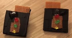
Backlights
The direction and the movement of the car controls the backlight.
When the car is in drive or in reverse mode, the Green LED lights up.
When the car is in stop mode, the Red LED lights up.
When the car is steering to the right, the right indicator is lit, while when it is steering to the left, the left indicator is lit.
Hardware Interface
In this section, you can describe how your hardware communicates, such as which BUSes used. You can discuss your driver implementation here, such that the Software Design section is isolated to talk about high level workings rather than inner working of your project.
Schematic
Software Design
**Drive, Steer and Speed signals from Master to Motor controller

 BO_ 209 MASTER_DRIVING_CAR: 8 MASTER
   SG_ MASTER_DRIVE_ENUM : 0|4@1+ (1,0) [0|0] "" MOTOR,COM_BRIDGE
   SG_ MASTER_STEER_ENUM : 4|4@1+ (1,0) [0|0] "" MOTOR,COM_BRIDGE
   SG_ MASTER_SPEED_ENUM : 8|4@1+ (1,0) [0|0] "" MOTOR,COM_BRIDGE
**Speed and distance travelled data from Motor to Master and Communication bridge controllers

 BO_ 147 MOTOR_CAR_SPEED: 4 MOTOR
   SG_ MOTOR_SPEED_DATA_UNSIGNED : 0|8@1+ (1,0) [0|0] "" MASTER,COM_BRIDGE
   SG_ MOTOR_DISTANCE_FROM_START_POINT_UNSIGNED : 8|8@1+ (1,0) [0|0] "meters" MASTER,COM_BRIDGE
**Heartbeat signal from Motor to Master Controller

 BO_ 339 MOTOR_HEARTBEAT: 2 MOTOR
   SG_ MOTOR_HEARTBEAT_UNSIGNED : 0|11@1+ (1,0) [0|0] "" MASTER
Implementation
Three signals - Drive, Speed and Steer signals are received by the Motor Controller from the Master.
Based on the signals received from the Master module, the motor is controlled.
| Sr No. | Enum Signal name | Signal from Master to Motor | Motor Algorithm | Functionality |
|---|---|---|---|---|
| 1 | Drive Signal |
|
|
|
| 2 | Speed Signal |
|
|
Speed of the car |
| 3 | Steer Signal |
|
|
Direction of the car |
Master-Motor IO Interface
Testing & Technical Challenges
1. Ideally at 7.5% duty cycle PWM, the servo motor should be aligned to center position, but due to faulty hardware the servo motor is inclined towards right giving us wrong movement.
We solved this problem by setting the PWM to 7.2% duty cycle during initialization, which resulted in accurate center position
2. For D.C motor to start running, we have to initialize the ESC. Hence without providing 1.5ms pulse at the beginning, the motor will start running.
3. As the battery voltage decreases, the motor does not run at the same speed with the same PWM. Hence with the decrease in speed we increased the PWM pulse linearly
4. In order to run the motor in reverse direction (when the motor is currently running in the forward direction), it was required to apply reverse pulse, then a stop pulse and again a reverse pulse, back to back.
Geographical Controller
Group Members
- Samiksha Ambekar
- Virginia Menezes
Schedule
| Sr No | Start Date | End Date | Task | Status | Actual Completed Date | Problems/Delay if any |
|---|---|---|---|---|---|---|
| 1 | 09/14/2016 | 09/20/2016 |
|
Completed | 09/20/2016 | |
| 2 | 09/21/2016 | 09/27/2016 |
|
Completed | 09/27/2016 | |
| 3 | 09/28/2016 | 10/04/2016 |
|
Completed | 10/04/2016 | |
| 4 | 10/05/2016 | 10/11/2016 |
|
Completed | 10/11/2016 | |
| 5 | 10/12/2016 | 10/18/2016 |
|
Completed | 10/18/2016 | |
| 6 | 10/19/2016 | 10/25/2016 |
|
Completed | 10/20/2016 | |
| 7 | 10/26/2016 | 11/01/2016 |
|
Completed | 10/31/2016 | |
| 8 | 11/02/2016 | 11/08/2016 |
|
Completed | 11/07/2016 | |
| 9 | 11/09/2016 | 11/15/2016 |
|
Completed | 11/13/2016 | |
| 10 | 11/16/2016 | 11/22/2016 |
|
Completed | 11/20/2016 | |
| 11 | 11/23/2016 | 11/29/2016 |
|
In Progress | ||
| 12 | 11/30/2016 | 12/06/2016 |
|
In Progress | ||
| 13 | 12/07/2016 | 12/13/2016 |
|
Design & Implementation
The Geographical Controller is used to track the current location of the car and the turn angle to steer to the next checkpoint.
The module comprises of a GPS module and a compass.
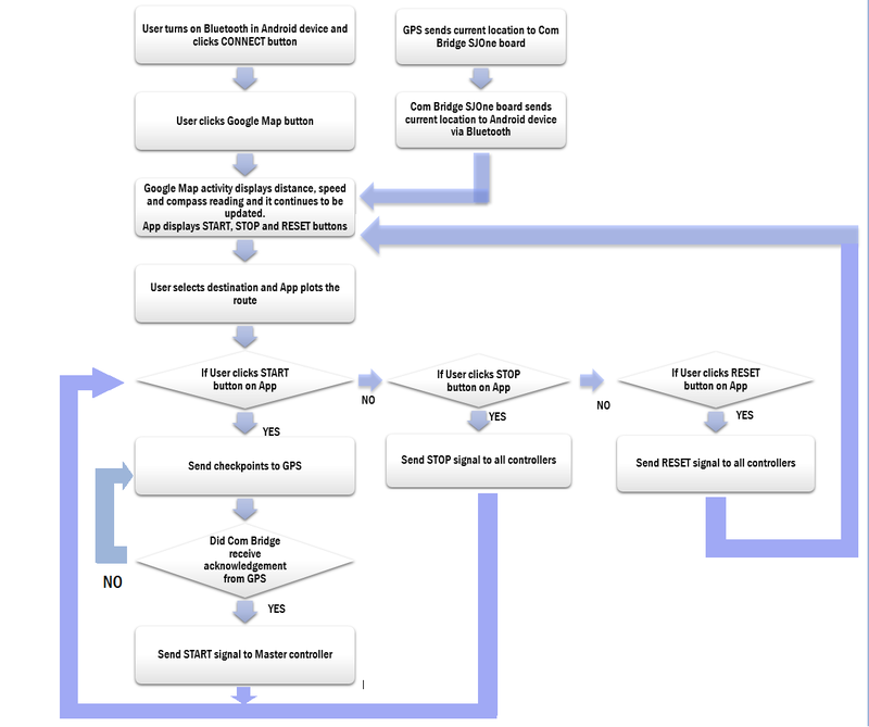
Once the user choses the destination point on the Android application, the app will map the shortest path available from the current location to the destination and plot multiple checkpoints based on that. The coordinates of these checkpoints are sent to the GEO controller, which will calculate the distance between the current location of the car and the next checkpoint and the turn angle required to reach the next checkpoint and send this information to the Master controller.
Hardware Design
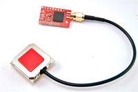
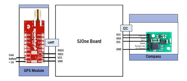
The GPS module used is SparkFun Venus GPS with SMA Connector [11]. And the Compass is CMPS11 - Tilt Compensated Compass Module [12].
GPS Module
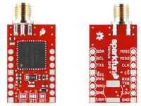
The GPS Module we use in our project is SparkFun Venus GPS with SMA Connector based on Venus638FLPx IC.
There are three modes of operation based on how it is powered:
1. Cold start: If no external battery (VBAT) of 3V is connected to the module, it will take a longer time to start and get a fix.
2. Hot start: When VBAT is connected to the module, even if the GPS is turned off and turned on within a certain time, it will get its fix from the value stored in memory.
3. Warm start: If the GPS is not turned on within the time frame for hot start (typically 2 hours), it will take sometime to get satellite fix.
GPS Configuration
The GPS module sends out the information in standard NMEA-0183 format or SkyTraq Binary sentence format. The default rate is 9600 bps and is configurable up to 115200 bps. The update rate of this GPS module is up to 20Hz. This indicates how often it recalculates and reports its position.
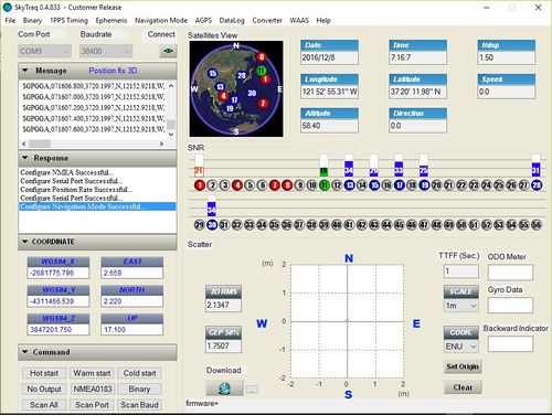
We have configured the GPS module using the GPS Viewer software provided by Skytraq.
1. The rate of UART is set at 38400bps
2. Update rate of 10Hz
3. Also it is possible to choose which NMEA message format we want the data in. For our car, we are using the GPGGA (Global Positioning System Fix Data) message format.
Apart from configuration, all other information like data received from the GPS, if fix position, no. of satellites, latitude and longitude etc. all can be viewed through this software.
GGA Message Structure : $GPGGA,hhmmss.sss,ddmm.mmmm,a,dddmm.mmmm,a,x,xx,x.x,x.x,M,,,,xxxx*hh<CR><LF>

Example data: $GPGGA,120218.899,2400.0000,N,12100.0000,E,0,00,0.0,0.0,M,0.0,M,,0000*69

      where,
                $GPGGA   -- Global Positioning System Fix Data (Sentence Identifier)
            120218.899   -- UTC Time of position in hhmmss.sss format
             2400.0000   -- Latitude in ddmm.mmmm format
                     N   -- Latitude hemisphere indicator, ‘N’ = North, ‘S’ = South
            12100.0000   -- Longitude in dddmm.mmmm format
                     E   -- E/W Indicator
                     0   -- GPS quality indicator
                              0: position fix unavailable
                              1: valid position fix, SPS mode
                              2: valid position fix, differential GPS mode
                              3: GPS PPS Mode, fix valid
                              4: Real Time Kinematic. System used in RTK mode with fixed integers
                              5: Float RTK. Satellite system used in RTK mode. Floating integers
                              6: Estimated (dead reckoning) Mode
                              7: Manual Input Mode
                              8: Simulator Mode
                    00   -- Number of satellites in use (00~12)
                   0.0   -- HDOP (Horizontal dilution of precision), (00.0 ~ 99.9)
                 0.0,M   -- Altitude in Meters - above mean sea level, (-9999.9 ~ 17999.9)
                 0.0,M   -- Height of geoid above WGS84 ellipsoid (mean sea level), (-9999.9 ~ 17999.9)
                  0000   -- DGPS Station ID - Differential reference station ID, 0000 ~ 1023
                            NULL when DGPS not used
                   *69   -- Checksum (begins with *)
Compass Module
The Compass Module we use in our project is CMPS11 - Tilt Compensated Compass Module. It employs a 3-axis magnetometer, 3-axis gyro and a 3-axis accelerometer. A Kalman filter is used to combine the gyro and accelerometer to remove the errors caused by tilting of the PCB. The output of the three sensors measuring x, y and z components of the magnetic field, together with the pitch and roll are used to calculate the bearing. It requires a power supply of 3.6-5V. The module can be operated in two modes - serial or I2C.
Hardware Interface
Schematic
Software Design
Algorithm
- Wait for START signal from COM Bridge
- Get current readings from GPS and compass module.
Implementation
This section includes implementation, but again, not the details, just the high level. For example, you can list the steps it takes to communicate over a sensor, or the steps needed to write a page of memory onto SPI Flash. You can include sub-sections for each of your component implementation.
Testing & Technical Challenges
Describe the challenges of your project. What advise would you give yourself or someone else if your project can be started from scratch again? Make a smooth transition to testing section and described what it took to test your project.
Android and Communication Bridge Controller
Group Members
- Nikhil Namjoshi
- Saurabh Deshmukh
Schedule
| Sr No | Start Date | End Date | Task | Status | Actual Completed Date |
|---|---|---|---|---|---|
| 1 | 9/27/2016 | 10/4/2016 |
|
Complete | 10/4/2016 |
| 2 | 10/6/2016 | 10/8/2016 |
|
Complete | 10/8/2016 |
| 3 | 9/30/2016 | 10/2/2016 |
|
Complete | 10/2/2016 |
| 4 | 10/2/2016 | 10/6/2016 |
|
Complete | 10/6/2016 |
| 5 | 10/10/2016 | 10/25/2016 |
|
In Progress | |
| 6 | 10/25/2016 | 11/2/2016 |
|
Completed | 10/31/2016 |
| 7 | 11/3/2016 | 11/11/2016 |
|
||
| 8 | 11/12/2016 | 11/23/2016 |
|
||
| 9 | 11/26/2016 | 12/5/2016 |
|
Design & Implementation
The design section can go over your hardware and software design. Organize this section using sub-sections that go over your design and implementation.
Hardware Design
Bluetooth Module
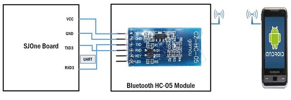
We are using Bluetooth module HC-05 to establish wireless communication between SJOne and the Android device. This module includes the Radio and Memory chips, 26 MHz crystal, antenna and RF matching network. The right section of the BT Board has connection pins for power and signals as well as a 5V to 3.3V Regulator, LED, and level shifting
Hardware Interface
Software Design
Implementation
This section includes implementation, but again, not the details, just the high level. For example, you can list the steps it takes to communicate over a sensor, or the steps needed to write a page of memory onto SPI Flash. You can include sub-sections for each of your component implementation.
Testing & Technical Challenges
Describe the challenges of your project. What advise would you give yourself or someone else if your project can be started from scratch again? Make a smooth transition to testing section and described what it took to test your project.
Conclusion
Conclude your project here. You can recap your testing and problems. You should address the "so what" part here to indicate what you ultimately learnt from this project. How has this project increased your knowledge?
Project Video
Upload a video of your project and post the link here.
Project Source Code
References
Acknowledgement
Any acknowledgement that you may wish to provide can be included here.
References Used
List any references used in project.
Appendix
You can list the references you used.
