|
|
| Line 371: |
Line 371: |
| | === Hardware Design === | | === Hardware Design === |
| | The sensors are interfaced using Port 2 GPIO pins of the microcontroller. The sensors require 5V power supply, which was provided from the main board’s supply. The trigger input to the sensors and the PWM output are interfaced to the GPIO pins as shown below in table. The pins for each sensor are chosen in such a way that it would not tangle each other while physically connecting them on the main board. CAN 1 of the SJOne board is connected to the CAN bus of the car which is also shown in the table below. | | The sensors are interfaced using Port 2 GPIO pins of the microcontroller. The sensors require 5V power supply, which was provided from the main board’s supply. The trigger input to the sensors and the PWM output are interfaced to the GPIO pins as shown below in table. The pins for each sensor are chosen in such a way that it would not tangle each other while physically connecting them on the main board. CAN 1 of the SJOne board is connected to the CAN bus of the car which is also shown in the table below. |
| | + | |
| | + | {| class="wikitable" |
| | + | |- |
| | + | ! scope="col"| Pin Name |
| | + | ! scope="col"| Function |
| | + | |- |
| | + | |- |
| | + | |1 |
| | + | |P2_0 |
| | + | |Trigger for left sensor |
| | + | |- |
| | + | |- |
| | | | |
| | === Hardware Interface === | | === Hardware Interface === |
Revision as of 20:32, 8 December 2016
Project Title
Autonomous Navigating RC Car
Abstract
This section should be a couple lines to describe what your project does.
Objectives & Introduction
Show list of your objectives. This section includes the high level details of your project. You can write about the various sensors or peripherals you used to get your project completed.
Track Progress in KanBan
Team Members & Responsibilities
- Master Controller
- Haroldo Filho
- Urvashi Agrawal
- Motor Controller & I/O Module
- GPS/Compass Module
- Yang Thao (GPS)
- Daamanmeet Paul (Compass)
- Sensors
- Communication Bridge/Android App
- Parth Pachchigar
- Purvil Kamdar
Project Schedule
Legend: Motor & I/O Controller , Master Controller , Communication Bridge Controller, Geographical Controller, Sensor Controller , Team Goal
| Week#
|
Start Date
|
End Date
|
Task
|
Status
|
| 1
|
09/13/2016
|
09/20/2016
|
- Order Components and work distribution.
- Research on the type and model of sensors to use and order them.
- Research on components requirement based on past projects.
- Order motor controller related components: Traxxas RPM sensor, (Servo motor, DC motor and ESC)Included in traxxas RC car.
- Reverse engineering Traxxas ESC, signal receiver, and signal transmitter to learn about basic functionality of the car.
- Android Development Environment Setup. Map API fundamental study.
|
Completed
|
| 2
|
09/21/2016
|
09/27/2016
|
- Set up git and wiki page
- Study the data sheet of sensor & prepare a high level design.
- Interface the sonic sensor to the sensor controller.
- Experiment and Research on voltage requirements for Servo and DC motor.
- Experiment and Research on PWM frequency requirements for DC and Servo motor.
- Experiment and Research on duty cycle required for controlling steer and speed of the car.
- Bluetooth BLE related android programming study and BLE protocol study.
|
Completed
|
| 3
|
09/28/2016
|
10/04/2016
|
- Receive Components and distribute to group members.
- Interface all the front sensors and test the readings with different environment conditions.
- Interface the SJ One Board to car's ESC(Electronic Speed Controller) and servo motor and test research results.
- Decide on the CAN ids and the priorities of the CAN messaged for various nodes.
- Basic Android Application development, Intent passing, Finalize GUI template.
|
Completed
|
| 4
|
10/05/2016
|
10/11/2016
|
- Agree on control system architecture, assign CAN node priorities and decide on communication paradigm between Master and Nodes. Prep for prototype.
- Stress test the sensors and design a filter so that reliable readings are sent to the master.
- Experiment and research on precision control of speed and steering using signals from SJ One board.
- Developing the framework for the I/O display and setting up SPI framework to read the CAN messages.
- Design the barebones basic functionality of the algorithm. Create a skeleton code.
- Controlling Bluetooth of Mobile Phone(i.e. Turn on, Connect), Connect Mobile phone with Bluetooth BLE module on SJOne.
|
Completed
|
| 5
|
10/12/2016
|
10/17/2016
|
- Testing week for all nodes. Goal is for each node to have a basic interface to their sensors and actuators in place, where they are able to read data and manipulate control signals. For instance: sensors node should be reading distance, motors node should be able to generate motor speed control signals. Modify the necessary parts in the CAN.dbc file.
- Interface back sensor and test all the sensors together.
- Debug and fix any issues.
- Design software filter to filter CAN messages required for motor controller.
- Get readings from the RPM sensor.
- Read the CAN messages to display on the LCD connected to the SJ One board.
- Set up CAN communication between the sensor,motor and the master. Test for correct data transmission.
- Establishing basic communication between Android phone and SJOne Board.
|
Completed
|
| 6
|
10/18/2016
|
10/24/2016
|
- Interface all nodes over Can bus and coordinate order and status message transfers between Master and Nodes. PCAN interface should be built to view & test CAN messages via Busmaster.
- Integrate sensors with other nodes via CAN and test the sensor values while the car is on the move.
- The master should have reliable data from sensors by now.
- Send signals to the motor controller from another CAN Node to control speed and steering using CAN interface.
- Creating necessary display messages and graphics related to the I/O modules.
- Design the algorithm to process the data received from the sensors and motors by the master.
- Integrate Google Map, Get Longitude and Latitude data from the position where Marker is placed, Get important data of other nodes from CAN bus.
|
Completed
|
| 7
|
10/25/2016
|
10/31/2016
|
- Integrate all hardware to the RC car, including power supplies from batteries. Test self powered prototype with the goal of controlling forward, reverse, left and right with start/stop command from the phone app. Test & fix basic integration bugs.
- Integrating and testing motor & I/O controller with other nodes.
- Extend the algorithm to control the motors along with the obstacle information received from the sensors.
- Integrate bridge controller with other modules via CAN. Test & fix basic integration bugs.
|
Completed
|
| 8
|
11/1/2016
|
11/7/2016
|
- Continue with hardware/software development & integration and complete first prototype of the collision avoidance feature.
- Design sensor mounts and 3D print them.
- Test and fine tune the algorithm developed so far for the first demo.
- Put multiple markers on Map and implement logic to find shortest route to destination and pass route information on CAN bus.
|
Completed
|
| 9
|
11/8/2016
|
11/14/2016
|
- Integrate GPS coordinates from Android app into Master Node for autonomous feature.
- Mount the sensors and test for any dead band. Position them for maximum coverage.
- Obtain the data from the GPS and process the data to design the algorithm for navigation. Design and implement the kill switch to avoid the car from crashing.
- Integrate GPS coordinates from Android app into Master Node for autonomous feature. Testing and Bug fixing.
|
In Process
|
| 10
|
11/15/2016
|
11/21/2016
|
- Integrate all nodes into one. Start testing car's autonomous driving capabilities with path following from GPS waypoints from Android app.
- Tune & optimize the sensor filter logic and the sensor mount as required.
- Integrate all the modules and test for the functionality. Save the data received from various modules into a log file for debugging purpose.
|
Not Started
|
| 11
|
11/22/2016
|
11/28/2016
|
- Autonomous driving should be working by now. Focus on improving car's performance. Tweak all nodes to better performance, and fix last minutes bugs.
- Interface Head lights and turn them ON based on light sensor value.
- Include the headlights and the LCD on the car and display messages on them.
|
Not Started
|
| 12
|
11/22/2016
|
11/28/2016
|
- Stress test the car with different environment scenarios.
- Improvise the algorithm and carry out stress testing and integration testing. Work on the modifications required and test previous hardware additions to the car.
|
Not Started
|
| 13
|
11/29/2016
|
Presentation date
|
- Final touches to improve overall vehicle's robustness. Self-fixing nodes, reduce/eliminate unexpected behaviors and crashes.
- Integration and testing. Work to improvise on the algorithms and make sure individual modules work. Addition of any extra features and software development.
|
Not Started
|
Parts List & Cost
| Item#
|
Part Desciption
|
Vendor
|
Qty
|
Cost
|
| 1
|
RC Car - Traxxas 1/10 Slash 2WD
|
Amazon
|
1
|
$189.95
|
| 2
|
Traxxas 2872X 5000mAh 11.1V 3S 25C LiPo Battery
|
Amazon
|
1
|
$56.99
|
| 3
|
Traxxas 7600mAh 7.4V 2-Cell 25C LiPo Battery
|
Amazon
|
1
|
$70.99
|
| 4
|
Traxxas 2970 EZ-Peak Plus 4-Amp NiMH/LiPo Fast Charger
|
Amazon
|
1
|
$35.99
|
| 5
|
Bluetooth 4.0 BLE Bee Module (Dual Mode)
|
Robotshop
|
1
|
$19.50
|
| 6
|
4D systems 32u LCD
|
4D systems
|
1
|
$41.55
|
| 7
|
LV Maxsonar EZ0 Ultrasonic sensors
|
Robotshop
|
5
|
$124.75
|
| 8
|
Devantech SF05 Ultrasonic sensor
|
Provided by Preet
|
1
|
Free
|
| 9
|
Venus GPS with SMA connector
|
Amazon
|
1
|
$49.95
|
| 10
|
SMA Male Plug GPS Active Antenna
|
Amazon
|
1
|
$9.45
|
| 11
|
Wire wrapping board
|
Radio shack
|
1
|
$20.0
|
| 12
|
CAN tranceivers
|
Digikey
|
1
|
$2.0
|
| 13
|
SJOne Boards
|
Provided by Preet
|
5
|
$400.0
|
DBC File Implementation
- The following is the DBC file of the project.
VERSION ""
NS_:
 NS_DESC_
 CM_
 BA_DEF_
 BA_
 VAL_
 CAT_DEF_
 CAT_
 FILTER
 BA_DEF_DEF_
 EV_DATA_
 ENVVAR_DATA_
 SGTYPE_
 SGTYPE_VAL_
 BA_DEF_SGTYPE_
 BA_SGTYPE_
 SIG_TYPE_REF_
 VAL_TABLE_
 SIG_GROUP_
 SIG_VALTYPE_
 SIGTYPE_VALTYPE_
 BO_TX_BU_
 BA_DEF_REL_
 BA_REL_
 BA_DEF_DEF_REL_
 BU_SG_REL_
 BU_EV_REL_
 BU_BO_REL_
 SG_MUL_VAL_
BS_:
BU_: DBG MASTER GPS MOTOR SENSOR APP
BO_ 1 APP_START_STOP: 1 APP
 SG_ APP_START_STOP_cmd : 0|8@1+ (1,0) [0|0] "COMMAND" MASTER
BO_ 16 SENSOR_DATA: 3 SENSOR
 SG_ SENSOR_left_sensor : 0|8@1+ (1,0) [0|0] "Inches" MASTER,APP
 SG_ SENSOR_middle_sensor : 8|8@1+ (1,0) [0|0] "Inches" MASTER,APP
 SG_ SENSOR_right_sensor : 16|8@1+ (1,0) [0|0] "Inches" MASTER,APP
BO_ 32 MASTER_HB: 2 MASTER
 SG_ MASTER_SPEED_cmd : 0|8@1+ (1,0) [0|0] "" SENSOR,MOTOR,GPS,APP
 SG_ MASTER_STEER_cmd : 8|8@1+ (1,0) [0|0] "" SENSOR,MOTOR,GPS,APP
BO_ 65 GPS_Data: 8 GPS
 SG_ GPS_READOUT_valid_bit : 0|1@1+ (1,0) [0|1] "" MASTER,MOTOR,APP
 SG_ GPS_READOUT_read_counter : 1|6@1+ (1,0) [0|60] "" MASTER,MOTOR,APP
 SG_ GPS_READOUT_latitude : 7|28@1+ (0.000001,-90.000000) [-90|90] "" MASTER,MOTOR,APP
 SG_ GPS_READOUT_longitude : 35|29@1+ (0.000001,-180.000000) [-180|180] "" MASTER,MOTOR,APP
BO_ 66 COMPASS_Data: 2 GPS
 SG_ COMPASS_Heading : 0|9@1+ (1,0) [0|0] "Degree" MASTER,APP,MOTOR
BO_ 67 GEO_Header: 3 GPS
 SG_ GPS_ANGLE_degree : 0|12@1+ (0.1,-180) [-180.0|180.0] "Degree" MASTER,MOTOR,APP
 SG_ GPS_DISTANCE_meter : 12|12@1+ (0.1,0) [0.0|400.0] "Meters" MASTER,MOTOR,APP
BO_ 48 MOTOR_STATUS: 3 MOTOR
 SG_ MOTOR_STATUS_speed_mph : 0|16@1+ (0.001,0) [0|0] "mph" MASTER,APP,MOTOR
CM_ BU_ MASTER "The master controller driving the car";
CM_ BU_ MOTOR "The motor controller of the car";
CM_ BU_ SENSOR "The sensor controller of the car";
CM_ BU_ APP "The communication bridge controller of car";
CM_ BU_ GPS "GPS and compass controller of the car";
CM_ BO_ 100 "Sync message used to synchronize the controllers";
BA_DEF_ "BusType" STRING ;
BA_DEF_ BO_ "GenMsgCycleTime" INT 0 0;
BA_DEF_ SG_ "FieldType" STRING ;
BA_DEF_DEF_ "BusType" "CAN";
BA_DEF_DEF_ "FieldType" "";
BA_DEF_DEF_ "GenMsgCycleTime" 0;
BA_ "GenMsgCycleTime" BO_ 32 100;
BA_ "GenMsgCycleTime" BO_ 16 100;
BA_ "GenMsgCycleTime" BO_ 48 100;
BA_ "GenMsgCycleTime" BO_ 65 100;
BA_ "GenMsgCycleTime" BO_ 66 100;
Sensor Controller
Design & Implementation
The main purpose of the sensor controller is Obstacle avoidance and one of the straight forward way to achieve the goal is to use an Ultrasonic sensor.
Sensor controller being the “eye” of the project, lot of thoughts were put into deciding the right sensor to serve the purpose of obstacle avoidance. Considering the factors of reliability and cost, Maxbotix EZ0 ultrasonic sensor is chosen to be left and right sensors. EZ ‘0’ model is selected because it has the widest beam coverage of all the Maxbotix EZ series sensor models. Devantech SF05 ultrasonic sensor is selected for the middle sensor. A different model is used for middle sensor because of its different frequency, which avoids interference between sensors.
The sensors are mounted and tested at different angles so that the front three sensors cover a wide area, without leaving any dead or uncovered region.
Hardware Design
The sensors are interfaced using Port 2 GPIO pins of the microcontroller. The sensors require 5V power supply, which was provided from the main board’s supply. The trigger input to the sensors and the PWM output are interfaced to the GPIO pins as shown below in table. The pins for each sensor are chosen in such a way that it would not tangle each other while physically connecting them on the main board. CAN 1 of the SJOne board is connected to the CAN bus of the car which is also shown in the table below.
| Pin Name
|
Function
|
| 1
|
P2_0
|
Trigger for left sensor
|
Hardware Interface
In this section, you can describe how your hardware communicates, such as which BUSes used. You can discuss your driver implementation here, such that the Software Design section is isolated to talk about high level workings rather than inner working of your project.
Software Design
Show your software design. For example, if you are designing an MP3 Player, show the tasks that you are using, and what they are doing at a high level. Do not show the details of the code. For example, do not show exact code, but you may show psuedocode and fragments of code. Keep in mind that you are showing DESIGN of your software, not the inner workings of it.
Implementation
This section includes implementation, but again, not the details, just the high level. For example, you can list the steps it takes to communicate over a sensor, or the steps needed to write a page of memory onto SPI Flash. You can include sub-sections for each of your component implementation.
Testing & Technical Challenges
Describe the challenges of your project. What advise would you give yourself or someone else if your project can be started from scratch again?
Make a smooth transition to testing section and described what it took to test your project.
Motor & I/O Controller
Design & Implementation
The design section can go over your hardware and software design. Organize this section using sub-sections that go over your design and implementation.
Hardware Design
Discuss your hardware design here. Show detailed schematics, and the interface here.
Hardware Interface
In this section, you can describe how your hardware communicates, such as which BUSes used. You can discuss your driver implementation here, such that the Software Design section is isolated to talk about high level workings rather than inner working of your project.
Software Design
Show your software design. For example, if you are designing an MP3 Player, show the tasks that you are using, and what they are doing at a high level. Do not show the details of the code. For example, do not show exact code, but you may show psuedocode and fragments of code. Keep in mind that you are showing DESIGN of your software, not the inner workings of it.
Implementation
This section includes implementation, but again, not the details, just the high level. For example, you can list the steps it takes to communicate over a sensor, or the steps needed to write a page of memory onto SPI Flash. You can include sub-sections for each of your component implementation.
Testing & Technical Challenges
Describe the challenges of your project. What advise would you give yourself or someone else if your project can be started from scratch again?
Make a smooth transition to testing section and described what it took to test your project.
Geographical Controller
Design & Implementation
The design section can go over your hardware and software design. Organize this section using sub-sections that go over your design and implementation.
Hardware Design
Discuss your hardware design here. Show detailed schematics, and the interface here.
Hardware Interface
GPS Module: Readytosky Ublox NEO-M8N GPS Module
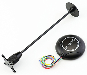
This GPS module uses UART serial communication interface. The refresh rate ranges from 1Hz up to 18Hz with a default baud rate of 9600bps. To achieve the desired refresh rate of 10Hz for our design, the baud rate had to be increased to 115200bps to accommodate for the demanded bandwidth from 10Hz refresh rate.
Specifications & Documentation:
www.u-blox.com
GPS Connector Definition:
- GND,
- TX,data output
- RX,data intput
- VCC,2.7V-3.6V
Why choose u-blox GPS module?
There are several reasons to select this GPS module oppose to other types such as Sparkfun's popular Venus GPS. First, is the price. The u-blox GPS module can be purchased off amazon for about $35 with integrated antenna compared to the Venus for $50 with an additional ~$10-15 for the required external antenna. This brings up the next point and that has to do with the external antenna. Since the antenna's coaxial cable can range between 10 to 15 feet, it becomes a hassle trying to tuck it away on once GPS module is mounted on the RC car. Second point is the accuracy. The u-blox's data sheet claims have an accuracy of about 2 meters (Amazon.com seller claims 0.6 to 0.9 meter) compared to 2.5 meters on the Venus. Although these different GPS modules uses their own software to configure its settings, they all are identically configurable. This means it is a no-brainer to go for the u-blox GPS module.
Setting up u-blox GPS module:
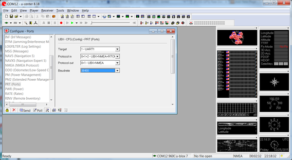
To be able to use u-blox center software to configure the GPS module, either u-blox's developer kit can be purchased or a cheaper alternative choice would be to purchase a FTDI USB to Serial adapter module for about $5 from any convenient online retailer. The u-blox software can be downloaded free from u-blox's website. Once connection is establish between the GPS module and computer, the software provides great number of configurations to change and also a wide GPS map tools to play with. Despite all the fun features the software provides, there are a few important settings that needed to be changed to fit our design.
On default, the refresh rate is set at 1000ms, or 1Hz. This had to be changed to 100ms to be able to get a refresh rate of 10Hz. Next, for the best accuracy possible from this GPS, Navigation Mode needs to be changed to "Pedestrian". This settings ensure best accuracy below speed of 30 meters/second which our RC car is well under. Lastly, since we are only interested in GPRMC messages from our GPS module, u-blox software provided option to turn off all messages except for GPRMC. This helps tremendously when trying to capture reliable messages.
The Readytosky GPS module has a soldered-on little super capacitor that charges up once power is provided and then acts as a battery once power is removed. Although this super capacitor helps by providing power to the memory to keep GSP configuration settings saved as well as provide a warm or hot start (faster to acquire accurate GPS data), it was only able to power for a few hours after power is removed. Although the datasheet says the memory is flash, it kept resetting back to default once battery power is gone. This meant configuration settings had to be redone often. To remedy this problem, the super capacitor had to be removed and in its place, a 3.3V coin battery soldered on.
Interfacing with SJ-One Board:
Interfacing this GPS module to the SJ-One board was straight forward. Since the communication type is UART, TX from GPS is tied to RXD2 pin on SJ-One and RX from GPS is tied to TXD2 pin utilizing UART2 port. Since the refresh rate was configured to 10hz, the default 9600 baud rate was not sufficient enough. Baud rate on both GPS module and SJ-One board both had to be changed to 115200 baud rate. Although baud could have lower and worked just fine, 115200 posed no issue so it was ideally better to get the message sooner and have a longer time in between the next message to avoid cascading messages in the UART read buffer.
**See Hardware Design for wire diagram.**
Razor IMU - 9 Degrees of Freedom
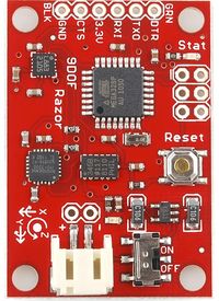
The 9DOF Razor IMU incorporates three sensors - an ITG-3200 (MEMS triple-axis gyro), ADXL345 (triple-axis accelerometer), and HMC5883L (triple-axis magnetometer) - to output nine degrees of inertial measurement. The outputs of all sensors are processed by an on-board ATmega328 and output over a serial interface.
Software Design
Show your software design. For example, if you are designing an MP3 Player, show the tasks that you are using, and what they are doing at a high level. Do not show the details of the code. For example, do not show exact code, but you may show psuedocode and fragments of code. Keep in mind that you are showing DESIGN of your software, not the inner workings of it.
Implementation
This section includes implementation, but again, not the details, just the high level. For example, you can list the steps it takes to communicate over a sensor, or the steps needed to write a page of memory onto SPI Flash. You can include sub-sections for each of your component implementation.
Testing & Technical Challenges
GPS Module
Communication Bridge Controller
Design & Implementation
The design section can go over your hardware and software design. Organize this section using sub-sections that go over your design and implementation.
Hardware Design
Here is the hardware block diagram of Communication Bridge Controller.
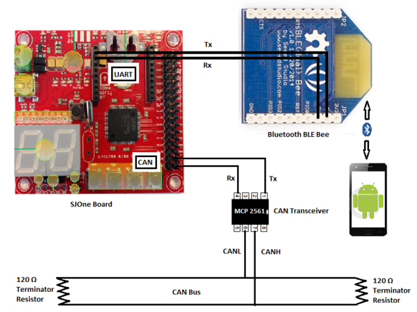
Hardware block diagram for Communication Bridge Module
Here is the hardware block diagram of Communication Bridge Controller.
Here is the hardware block diagram of Communication Bridge Controller.
Here is the hardware block diagram of Communication Bridge Controller.
Hardware Interface
In this section, you can describe how your hardware communicates, such as which BUSes used. You can discuss your driver implementation here, such that the Software Design section is isolated to talk about high level workings rather than inner working of your project.
Software Design
Show your software design. For example, if you are designing an MP3 Player, show the tasks that you are using, and what they are doing at a high level. Do not show the details of the code. For example, do not show exact code, but you may show psuedocode and fragments of code. Keep in mind that you are showing DESIGN of your software, not the inner workings of it.
Implementation
This section includes implementation, but again, not the details, just the high level. For example, you can list the steps it takes to communicate over a sensor, or the steps needed to write a page of memory onto SPI Flash. You can include sub-sections for each of your component implementation.
Testing & Technical Challenges
Describe the challenges of your project. What advise would you give yourself or someone else if your project can be started from scratch again?
Make a smooth transition to testing section and described what it took to test your project.
Master Controller
Design & Implementation
The design section can go over your hardware and software design. Organize this section using sub-sections that go over your design and implementation.
Hardware Design
Discuss your hardware design here. Show detailed schematics, and the interface here.
Hardware Interface
In this section, you can describe how your hardware communicates, such as which BUSes used. You can discuss your driver implementation here, such that the Software Design section is isolated to talk about high level workings rather than inner working of your project.
Software Design
Show your software design. For example, if you are designing an MP3 Player, show the tasks that you are using, and what they are doing at a high level. Do not show the details of the code. For example, do not show exact code, but you may show psuedocode and fragments of code. Keep in mind that you are showing DESIGN of your software, not the inner workings of it.
Implementation
This section includes implementation, but again, not the details, just the high level. For example, you can list the steps it takes to communicate over a sensor, or the steps needed to write a page of memory onto SPI Flash. You can include sub-sections for each of your component implementation.
Testing & Technical Challenges
Describe the challenges of your project. What advise would you give yourself or someone else if your project can be started from scratch again?
Make a smooth transition to testing section and described what it took to test your project.
My Issue #1
Discuss the issue and resolution.
Conclusion
Conclude your project here. You can recap your testing and problems. You should address the "so what" part here to indicate what you ultimately learnt from this project. How has this project increased your knowledge?
Project Video
Upload a video of your project and post the link here.
Project Source Code
References
Acknowledgement
Any acknowledgement that you may wish to provide can be included here.
References Used
List any references used in project.
Appendix
You can list the references you used.


