Difference between revisions of "F12: Evil Watchdog"
Waymond f12 (talk | contribs) (→Schedule) |
(→Appendix) |
||
| (116 intermediate revisions by 2 users not shown) | |||
| Line 1: | Line 1: | ||
==Abstract== | ==Abstract== | ||
| − | The Evil Watchdog takes the responsibilities of a pet guarding a house. | + | [[File:CMPE_146_F12_EWD_Evil_Watchdog.jpg|thumb|220px|A household dog.]]The Evil Watchdog takes the responsibilities of a pet guarding a house. Having a pet dog is one way that homeowners can protect their property. Dogs run quickly and bark loudly to scare away intruders. At the same time, dogs need extra care and attention during the day to maintain their livelihood. To eliminate the required care and attention of typical household canines, the electronic and autonomous Evil Watchdog was created. The Evil Watchdog takes the responsibilities of a pet guarding a house by roaming around an environment, navigating around obstacles, and sounding an alarm whenever foreign motion is detected. |
| − | |||
== Introduction == | == Introduction == | ||
| − | The | + | The team members have always been fascinated with dogs. Combined with their fascination with remote-controlled cars, this became the perfect project to further their understanding of how sensors can safely direct a car through a course. Out in the real world, autonomous cars are in their infancy, but are already making their way onto roadways. In many ways, autonomous cars act similarly to dogs. They travel from point to point as long as safety permits. The parts required for building the Evil Watchdog project are well within a college student’s budget. |
| − | |||
| − | |||
| − | |||
| − | + | The objective of this project was to design a vehicle to imitate a guard dog. The following criteria were incorporated to accomplish this goal: | |
| − | * | + | * A motor-driven chassis |
| − | * | + | * The vehicle will move in a path based on surroundings |
| + | * The vehicle will sound an alarm when motion is detected | ||
| − | ===Team Members | + | === Technology Used === |
| − | *Waymond Chen: Front motor control and distance sensor programming | + | * A motion sensor |
| − | *Hung Vuong: Distance and motion sensor programming | + | * A distance sensor |
| − | *Erik Montoya: Backside motor control and programming | + | |
| + | === Team Members === | ||
| + | * Waymond Chen | ||
| + | * Hung Vuong | ||
| + | * Erik Montoya | ||
| + | |||
| + | === Roles & Responsibilities === | ||
| + | * Waymond Chen: Front motor control and distance sensor programming | ||
| + | * Hung Vuong: Distance and motion sensor programming | ||
| + | * Erik Montoya: Backside motor control and programming | ||
==Schedule== | ==Schedule== | ||
| Line 105: | Line 111: | ||
</td> | </td> | ||
<td valign="top"> | <td valign="top"> | ||
| − | + | * Successfully tested entire vehicle | |
| + | * Updated project report</td> | ||
</tr> | </tr> | ||
<tr> | <tr> | ||
| Line 115: | Line 122: | ||
</td> | </td> | ||
<td valign="top"> | <td valign="top"> | ||
| − | + | * Updated project report | |
| + | * Scheduled demo day</td> | ||
| + | </tr> | ||
| + | <tr> | ||
| + | <td align="center">Dec 19, 2012</td> | ||
| + | <td align="center"> | ||
| + | Dec 19, 2012</td> | ||
| + | <td valign="top"> | ||
| + | * Demo project</td> | ||
| + | <td valign="top"> | ||
| + | * Presented project</td> | ||
</tr> | </tr> | ||
</table> | </table> | ||
==Parts List and Costs== | ==Parts List and Costs== | ||
| − | |||
<table class="wikitable"> | <table class="wikitable"> | ||
| − | <th>Item</th><th>Source</th> | + | <th>Item</th><th>Details</th> |
| + | <th>Source</th> | ||
<th>Cost Ea.</th> | <th>Cost Ea.</th> | ||
<th>Qty.</th> | <th>Qty.</th> | ||
<th>Total</th> | <th>Total</th> | ||
<tr> | <tr> | ||
| − | <td> | + | <td>Batteries</td> |
| − | + | <td align="left">Duracell 1.5V Size AA</td> | |
| − | |||
| − | |||
| − | |||
| − | |||
| − | |||
| − | |||
| − | <td align="left"> | ||
| − | |||
| − | |||
| − | |||
| − | |||
| − | |||
| − | |||
<td align="left">Costco</td> | <td align="left">Costco</td> | ||
<td align="right">$1.33</td> | <td align="right">$1.33</td> | ||
| Line 148: | Line 152: | ||
</tr> | </tr> | ||
<tr> | <tr> | ||
| − | <td> | + | <td>Distance Sensors</td> |
| − | <td align="left"> | + | <td align="left">SRF02 Ultrasonic Range Finder</td> |
| − | + | <td align="left">Preet Kang</td> | |
| − | |||
| − | |||
| − | |||
| − | |||
| − | |||
| − | <td align="left"> | ||
<td align="right">$25.00</td> | <td align="right">$25.00</td> | ||
<td align="center">x3</td> | <td align="center">x3</td> | ||
| Line 163: | Line 161: | ||
<tr> | <tr> | ||
<td>LEDs</td> | <td>LEDs</td> | ||
| + | <td align="left">Blue and Green LEDs</td> | ||
<td align="left">HSC Electronics</td> | <td align="left">HSC Electronics</td> | ||
<td align="right">$0.35</td> | <td align="right">$0.35</td> | ||
| Line 169: | Line 168: | ||
</tr> | </tr> | ||
<tr> | <tr> | ||
| − | <td>Motion Sensor | + | <td>Microcontroller</td> |
| + | <td align="left">ARM7 NXP LPC2148</td> | ||
| + | <td align="left">Preet Kang</td> | ||
| + | <td align="right">$60.00</td> | ||
| + | <td align="center">x1</td> | ||
| + | <td align="right">$60.00</td> | ||
| + | </tr> | ||
| + | <tr> | ||
| + | <td>Motion Sensor</td> | ||
| + | <td align="left">PIR Motion Sensor SEN-08630</td> | ||
<td align="left">Preet Kang</td> | <td align="left">Preet Kang</td> | ||
| − | <td align="right"> | + | <td align="right">$9.95</td> |
| − | <td align="center"> | + | <td align="center">x1</td> |
| − | <td align="right"> | + | <td align="right">$9.95</td> |
</tr> | </tr> | ||
<tr> | <tr> | ||
| − | <td>Motor Controllers | + | <td>Motor Controllers</td> |
| − | <td align="left">SJValley Engineering</td> | + | <td align="left">SJValley Engineering 5A Motor Controller</td> |
| − | <td align="right">$ | + | <td align="left">Dr. Özemek</td> |
| + | <td align="right">$17.99</td> | ||
<td align="center">x2</td> | <td align="center">x2</td> | ||
| − | <td align="right">$ | + | <td align="right">$35.98</td> |
</tr> | </tr> | ||
<tr> | <tr> | ||
| − | <td>Voltage Regulator | + | <td>Piezo Buzzer</td> |
| + | <td align="left">75dB 6VDC Piezo Buzzer</td> | ||
| + | <td align="left">RadioShack</td> | ||
| + | <td align="right">$3.89</td> | ||
| + | <td align="center">x1</td> | ||
| + | <td align="right">$3.89</td> | ||
| + | </tr> | ||
| + | <tr> | ||
| + | <td>RC Car</td> | ||
| + | <td align="left">New Bright Land Rover Mud Slinger</td> | ||
| + | <td align="left">Fry's Electronics</td> | ||
| + | <td align="right">$15.34</td> | ||
| + | <td align="center">x1</td> | ||
| + | <td align="right">$15.34</td> | ||
| + | </tr> | ||
| + | <tr> | ||
| + | <td>Voltage Regulator</td> | ||
| + | <td align="left">LM7805CV Voltage Regulator</td> | ||
<td align="left">HSC Electronics</td> | <td align="left">HSC Electronics</td> | ||
| − | <td align="right">$ | + | <td align="right">$2.00</td> |
<td align="center">x1</td> | <td align="center">x1</td> | ||
| − | <td align="right">$ | + | <td align="right">$2.00</td> |
</tr> | </tr> | ||
</table> | </table> | ||
| − | |||
==Design and Implementation== | ==Design and Implementation== | ||
| + | ===Hardware Design=== | ||
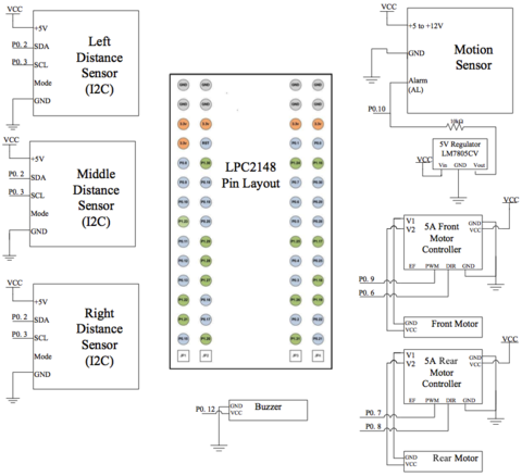
| + | The LPC2148 microcontroller allows for the integration of many components through various popular interfaces, such as I2C, UART, and SPI. The distance sensors were designed primarily for use with the I2C interface. Given the LPC2148's limited pin availability for I2C, pins 0.2 and 0.3 were reserved immediately to prevent additional components from occupying those important pins. Likewise, pins capable of carrying PWM signals were reserved for the rear motor controller. Those were pins 0.7 and 0.8. The GPIO interface was used for the remaining components: the front motor controller, the motion detector, and the alarm. The following diagram illustrates the connections between the LPC2148 microcontroller and the various components used in this project: | ||
| + | [[File:CMPE_146_F12_Pin_Layout.png|thumb|center|480px|Pin selection and connections (click to enlarge).]] | ||
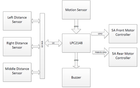
| + | The next block diagram displays the buses and interfaces used in the hardware design: | ||
| + | [[File:CMPE_146_F12_EWD_Blocks.png|thumb|center|480px|Pin selection and connections (click to enlarge).]] | ||
| − | ===Hardware | + | ===Hardware Implementation=== |
====Frame and Inner Placement==== | ====Frame and Inner Placement==== | ||
| − | [[File:CMPE_146_F12_Evil_Watchdog_Toy_Car.jpg|thumb|220px|Original toy car prior to disassembly.]]For convenience, a New Bright toy RC car was purchased and disassembled. The motors and wheels were already pre-mounted onto the chassis | + | [[File:CMPE_146_F12_Evil_Watchdog_Toy_Car.jpg|thumb|220px|Original toy car prior to disassembly.]]For convenience, a New Bright toy RC car was purchased and disassembled. The motors and wheels were already pre-mounted onto the chassis. Motor controllers could easily control the motors to drive and steer the vehicle. On the chassis, slots above the wheel wells were large enough to house motor controllers while the center of the chassis provided enough room to include a small breadboard and the microcontroller. All wires were shortened to the shortest length possible to reduce clutter. |
| − | ====Sensor Placement==== | + | ====Sensor and Alarm Placement==== |
| − | The sensors, which guided car control, were strategically mounted in front and above the car. This increased visibility of the sensors. Three distance sensors were used to detect obstacles: a left-, a center-, and a right-side sensor was used to determine steering of the vehicle. A front-mounted sensor | + | The sensors, which guided car control, were strategically mounted in front and above the car. This increased visibility of the sensors. Three distance sensors were used to detect obstacles: a left-, a center-, and a right-side sensor was used to determine steering of the vehicle. A front-mounted sensor sought motion as the car was stopped. Once motion was detected, the car promptly sounded the piezo buzzer alarm after determining that the motion was legitimate. |
====Power Supply==== | ====Power Supply==== | ||
| Line 208: | Line 238: | ||
<th>Source</th> | <th>Source</th> | ||
<tr> | <tr> | ||
| − | <td>Distance Sensors (Parallel)</td> | + | <td align="center">Distance Sensors (Parallel)</td> |
| − | <td align=" | + | <td align="center">+5V</td> |
<td align="center">Microcontroller Pin</td> | <td align="center">Microcontroller Pin</td> | ||
</tr> | </tr> | ||
<tr> | <tr> | ||
| − | <td>LPC2148 Microcontroller</td> | + | <td align="center">LPC2148 Microcontroller</td> |
| − | <td align=" | + | <td align="center">+7V to +20V</td> |
<td align="center">Battery Pack</td> | <td align="center">Battery Pack</td> | ||
</tr> | </tr> | ||
<tr> | <tr> | ||
| − | <td>Motion Sensors</td> | + | <td align="center">Motion Sensors</td> |
| − | <td align=" | + | <td align="center">+5V to +12V</td> |
<td align="center">Battery Pack</td> | <td align="center">Battery Pack</td> | ||
</tr> | </tr> | ||
<tr> | <tr> | ||
| − | <td>Motor Controllers</td> | + | <td align="center">Motor Controllers</td> |
| − | <td align=" | + | <td align="center">+7V to +30V</td> |
<td align="center">Battery Pack</td> | <td align="center">Battery Pack</td> | ||
</tr> | </tr> | ||
<tr> | <tr> | ||
| − | <td>Piezo Buzzer</td> | + | <td align="center">Piezo Buzzer</td> |
| − | <td align=" | + | <td align="center">+3V to +6V</td> |
<td align="center">Microcontroller Pin</td> | <td align="center">Microcontroller Pin</td> | ||
</tr> | </tr> | ||
</table> | </table> | ||
| − | === | + | ====Motion Sensor==== |
| + | [[File:CMPE_146_F12_EWD_Motion.png|thumb|220px|Motion sensor.]] | ||
| + | The passive infrared sensor measures changes in the environment, using heat as an indicator. It signals the pin low when it detects a change in heat. Three pins, with associated wire colorings, are used: red for voltage source, brown for ground, and black for alarm signal. The alarm signal can be connected to any pin on the microcontroller that can handle GPIO. Also, a pull up resistor is needed on the pin to GPIO. The pull up resistor is required because the sensor alarm pin is an open collector. Without this resistor, the value of the alarm will merely fluctuate between low and high constantly. Shown below are the connections between the microcontroller and the alarm: | ||
| + | |||
| + | <table class="wikitable"> | ||
| + | <th>Microcontroller</th><th>Motion Sensor</th> | ||
| + | <tr> | ||
| + | <td align="center">VCC (7.5V) </td> | ||
| + | <td align="center">VCC (7.5V) </td> | ||
| + | </tr> | ||
| + | <tr> | ||
| + | <td align="center">GND</td> | ||
| + | <td align="center">GND</td> | ||
| + | </tr> | ||
| + | <tr> | ||
| + | <td align="center"> P0.10 </td> | ||
| + | <td align="center">Alarm (AL)</td> | ||
| + | </tr> | ||
| + | </table> | ||
| + | |||
| + | ==== Alarm ==== | ||
| + | [[File:CMPE_146_F12_EWD_Alarm.png|thumb|220px|75dB piezo buzzer.]] | ||
| + | The 75dB alarm can handle up to 6 volts of power. A quick test on the voltage generator showed that 3 volts, which comes from a GPIO output pin, was plenty to create an audible sound. | ||
| + | |||
| + | <table class="wikitable"> | ||
| + | <th>Microcontroller</th><th>Alarm</th> | ||
| + | <tr> | ||
| + | <td align="center">P0.12</td> | ||
| + | <td align="center">VCC (3.3V) </td> | ||
| + | </tr> | ||
| + | <tr> | ||
| + | <td align="center"> GND</td> | ||
| + | <td align="center">GND</td> | ||
| + | </tr> | ||
| + | </table> | ||
| + | |||
| + | ====Distance Sensor==== | ||
| + | [[File:CMPE_146_F12_EWD_Dist.png|thumb|220px|Distance sensor.]] | ||
| + | The SRF02 ultrasonic range finder (distance sensor) can operate through serial mode or I2C mode. This device carries five pins: +5V VCC, SDA, SCL, Mode, and Ground. Since the I2C mode is used, the mode pin doesn’t need to connect to anything. The SCL and SDA lines are connected to the pins that support SCL0 and SDA0 on the microcontroller. These pins also need a pair of resistors because I2C is an open collector. | ||
| + | |||
| + | <table class="wikitable"> | ||
| + | <th>Microcontroller</th><th>Distance Sensor</th> | ||
| + | <tr> | ||
| + | <td align="center">Regulator (+5V) </td> | ||
| + | <td align="center">VCC (+5V) </td> | ||
| + | </tr> | ||
| + | <tr> | ||
| + | <td align="center"> P0.2 </td> | ||
| + | <td align="center"> SDA </td> | ||
| + | </tr> | ||
| + | <tr> | ||
| + | <td align="center"> P0.3 </td> | ||
| + | <td align="center"> SCL </td> | ||
| + | </tr> | ||
| + | <tr> | ||
| + | <td align="center"> GND</td> | ||
| + | <td align="center">GND</td> | ||
| + | </tr> | ||
| + | </table> | ||
| + | |||
| + | ====5A Motor Controllers==== | ||
| + | [[File:CMPE_146_F12_EWD_MC.png|thumb|220px|5A motor controller.]] | ||
| + | The motor controllers were used to adjust speed on the motors. The controllers maintain a continuous 5A current while applying voltage. Interfacing the motor controllers requires three pins: PWM, direction, and ground. Pins were initiated prior to using the motor controllers. The rear motor used PWM while the front motor used GPIO in place of PWM. | ||
| + | |||
| + | <table class="wikitable"> | ||
| + | <th>Microcontroller</th><th>Front Motor Controller</th> | ||
| + | <tr> | ||
| + | <td align="center">VCC (7.5v) </td> | ||
| + | <td align="center">VCC (7.5v) </td> | ||
| + | </tr> | ||
| + | <tr> | ||
| + | <td align="center"> P0.9 </td> | ||
| + | <td align="center"> PWM </td> | ||
| + | </tr> | ||
| + | <tr> | ||
| + | <td align="center"> P0.6 </td> | ||
| + | <td align="center"> DIR </td> | ||
| + | </tr> | ||
| + | <tr> | ||
| + | <td align="center"> GND</td> | ||
| + | <td align="center">GND</td> | ||
| + | </tr> | ||
| + | </table> | ||
| + | |||
| + | <table class="wikitable"> | ||
| + | <th>Microcontroller</th><th>Rear Motor Controller</th> | ||
| + | <tr> | ||
| + | <td align="center">VCC (7.5v) </td> | ||
| + | <td align="center">VCC (7.5v) </td> | ||
| + | </tr> | ||
| + | <tr> | ||
| + | <td align="center"> P0.7 </td> | ||
| + | <td align="center"> PWM </td> | ||
| + | </tr> | ||
| + | <tr> | ||
| + | <td align="center"> P0.8 </td> | ||
| + | <td align="center"> DIR </td> | ||
| + | </tr> | ||
| + | <tr> | ||
| + | <td align="center"> GND</td> | ||
| + | <td align="center">GND</td> | ||
| + | </tr> | ||
| + | </table> | ||
| + | |||
| + | ==== Switch ==== | ||
| + | [[File:CMPE_146_F12_EWD_Switch.png|thumb|220px|Switch added to circuitry.]] | ||
| + | A single-pole double-throw switch was added to the board to quickly connect and disconnect power to the system. | ||
===Software Design=== | ===Software Design=== | ||
| + | ==== Using FreeRTOS ==== | ||
| + | FreeRTOS, a real-time operating system, was used to program the hardware used on the vehicle. FreeRTOS mainly uses C while allowing for some expansion into C++. Its support for tasks and semaphores made it a convenient platform for writing and implementing software for this project. Furthermore, FreeRTOS requires a small amount of memory while running tasks quickly and efficiently. | ||
| + | |||
| + | Several labs built using FreeRTOS were completed prior to starting this project, which contributed to a good understanding of the FreeRTOS system. The basic coding structure used for the labs also served as the basic coding framework for the Evil Watchdog. | ||
| + | |||
| + | ==== Part-by-part Expansion ==== | ||
| + | Once all the necessary parts were collected, each part received its own dedicated piece of code and its own testing before becoming integrated with the other parts used for the car. Intuitively, the motor controllers were selected as the first parts for writing code, because the vehicle's movement depended entirely on the motors and wheels. Each motor controller can regulate the speed at which the attached wheels spin, through the use of pulse-width modulation (PWM). Looking at the car, only the rear wheels need speed control. It was not necessary to implement PWM on the front wheels because those wheels are used for steering and simply require steering extreme left, extreme right, or straight, thanks to the car's small size. The rear wheels were controlled through PWM, and the front wheels through GPIO. | ||
| + | |||
| + | ==== Pulse-width Modulation ==== | ||
| + | Pulse-width modulation, or PWM, allows a motor controller to govern the speed at which a motor turns. Two key features of a PWM driver are the frequency, which determines how often a cycle repeats, and the duty cycle, which controls the speed of the motor spinning. The PWM driver allows the microcontroller to send out pulses based on the frequency and duty cycle settings, similar to a person flapping a rope up and down with the other end of the rope attached to a wall. By changing the PWM's frequency, the vehicle's rear motors could be slowed down or sped up. The board pins were set up accordingly: | ||
| + | # Reset P0.7 | ||
| + | # Assign P0.7 for PWM2 | ||
| + | # Assign P0.8 for direction (GPIO) | ||
| + | # Set P0.8 direction as output | ||
| + | |||
| + | The PWM driver was initialized, too: | ||
| + | [[File:CMPE_146_F12_EWD_PWMinit.png|thumb|center|175px|Initializing the PWM driver.]] | ||
| + | The PWM registers had to be set accordingly. Looking at the LPC2148 datasheet, the registers shown above were configured: | ||
| + | * PWMTCR: Timer control. Reset first with bit 1. | ||
| + | * PWMPR: Prescale. Increments every PCLK cycle. Set to zero. | ||
| + | * PWMMCR: Match control. Control if interrupt is generated. Will reset on MR0. | ||
| + | * PWMPCR: Control. Enables PWM in single-edge mode. | ||
| + | * PWMMR0: PWM period. Set to 48000 Hz to match CPU. | ||
| + | * PWMMR2: Duty cycle/PWM width. Compared to PWMMR0. Output duty is inversely related to PWMMR0. | ||
| + | * PWMLER: Latch enable. Latch in all PWMMRx. | ||
| + | * PWMTCR: Timer control (again). Enable counter with bits 0 and 3. | ||
| + | |||
| + | With the PWM registers initialized, the duty cycle could later be modified to change motor speed. PWMMR2 was used in this case. Therefore, if a change in motor speed was necessary, PWMMR2 could be set inclusively between 0 and 48000 to change the duty cycle. | ||
| + | |||
| + | ==== Steering Control ==== | ||
| + | At first, it seemed a good idea that PWM be used on the front motor controller. After attempting to establish PWM on the steering side of the car, Preet recommended that GPIO could handle the steering job just as well. The pins had to be initialized first: | ||
| + | # Assign P0.9 as GPIO for controlling full or zero power | ||
| + | # Set P0.9 as output | ||
| + | # Assign P0.6 as GPIO for direction | ||
| + | # Set P0.6 as output | ||
| + | The most difficult part of using GPIO for steering was mapping out which voltages corresponded to which steering direction. The motor controller could turn extreme left, extreme right, or stayed straight. To help determine the directions, a handy table was created: | ||
| + | <table class="wikitable"> | ||
| + | <th>Controller</th> | ||
| + | <th>GPIO Low (0V)</th><th>GPIO High (+3.3V)</th> | ||
| + | <tr> | ||
| + | <td align="center">PWM Pin</td> | ||
| + | <td align="center">Power</td> | ||
| + | <td align="center">No Power</td> | ||
| + | </tr> | ||
| + | <tr> | ||
| + | <td align="center"> DIR Pin</td> | ||
| + | <td align="center"> Left</td> | ||
| + | <td align="center"> Right</td> | ||
| + | </tr> | ||
| + | </table> | ||
| + | Changing the motor between go/stop and left/right was done by either setting the P0.6 or P0.9 pins, respectively, to 1 or 0 using IOSET0 and IOCLR0. Using the help of LEDs, the correct directions and power distribution was mapped for the motor controller. It was interesting to note that to get back to center, a change of direction had to take place. For example, if the car was heading left, it had to be steered back to the right to "release" the left steering before returning to center position. | ||
| + | |||
| + | ==== Distance Sensors: I2C ==== | ||
| + | The distance sensors were designed for use on the I2C or serial buses. Based on pin availability and software convenience, I2C was used to gather distance information from the sensors. The next question was: How would the microcontroller distinguish between the three sensors? A glance at the technical specifications provided the solution. Each sensor was equipped with a handy LED that flashed its address in a recognizable sequence. Each sequence was one long flash, accompanied by a number of short flashes. The short flashes represented the difference in the current address from 0xE0 in increments of 0x02, up to 15 short flashes. Legal addresses ranged from 0xE0 to 0xFE. | ||
| + | |||
| + | By comparing the sequence emitted, a programmer could determine the sensor's set address. Also, its address could be altered to allow the I2C to accommodate additional sensors, though each sensor must be programmed individually, one at a time. This sequence was used to set each sensor: | ||
| + | # Get sensor address | ||
| + | # Send 0xA0 to address | ||
| + | # Send 0xAA to address | ||
| + | # Send 0xA5 to address | ||
| + | # Send new address to address | ||
| + | |||
| + | For convenience, the following addresses were selected for the sensors: 0xE2 for the left sensor, 0xE4 for the center, and 0xE6 for the right. | ||
| + | [[File:CMPE_146_F12_EWD_DistCode.png|center|frame|461px|Code to gather information from center sensor.]] | ||
| + | An I2C call is made when the microcontroller wants to retrieve information from the distance sensors. The I2C bus is shared, and the program allocates enough time to release slave devices when required. The "unit_command" variable was set to 81 to force the sensor to measure distances in centimeters. If the user wants to opt for measurements in inches, the variable can simply be changed to 80. | ||
| + | |||
| + | Locations 2 and 3 hold the newest reading in a 16-bit unsigned integer format. Through high and low bytes, the sensor readings could be retrieved. The datasheet warns that it is best to give a minimum of 65 milliseconds for the pings to fade away properly. In the code, a 75 ms vTaskDelay was added to accommodate for the wait. | ||
| + | |||
| + | ====Motion Sensor ==== | ||
| + | As with the front motor, the pins for the motion sensor were initialized: | ||
| + | # Assign P0.10 as GPIO | ||
| + | # Set P0.10 as input | ||
| + | |||
| + | A GPIO input pin was designated on the microcontroller to interact with the motion sensor. The motion sensor dropped its voltage to zero whenever motion was detected, which registered sufficient data for the pin on the board. | ||
| + | |||
| + | To check for motion, the code looked for a zero on the P0.10 pin. | ||
| + | |||
| + | The system surveyed for motion eight times in 500 millisecond intervals. When motion was detected in five out of those eight intervals, the alarm was sounded. This prevented false alarms from occurring, in the event that stray, non-legitimate motion came across the sensor's environment. This diagram shows the motion surveying method: | ||
| + | [[File:CMPE_146_F12_EWD_Motion_Flow.png|center|frame|529px|Motion sensor polling sequence.]] | ||
| + | |||
| + | ==== Alarm Triggering ==== | ||
| + | One more GPIO pin was used for the alarm: | ||
| + | # Assign P0.12 as GPIO | ||
| + | # Set P0.12 as output | ||
| + | |||
| + | Whenever the pin was set active, the alarm rang. Turning the alarm on and off was based on whether motion was detected. Using IOSET and IOCLR to change the pin to 1 and 0 was done through functions. | ||
| + | |||
| + | ==== Loading the Software ==== | ||
| + | [[File:CMPE_146_F12_EWD_Hyperload.png|thumb|220px|HyperLoad 1.1 interface.]]Once the program was built and compiled, a .hex file was generated, which contained the program that will be read by the microcontroller. The .hex file was transferred from computer to microcontroller through a USB cable. HyperLoad 1.1 was run on the programming computer to interact with the microcontroller via USB. Setting up HyperLoad 1.1 included changing the COM port speed to 500000 bps and target CPU frequency to 48000000. The .hex file was chosen, the proper port was opened, and the file was transferred. | ||
===Software Implementation=== | ===Software Implementation=== | ||
| + | ==== Task Flowchart ==== | ||
| + | The program was designed to run by employing tasks that handled sensor readings and appropriate outputs. A "drive" task was assigned to handle vehicular driving, and a "SensorValue" task was assigned to continuously capture data from the distance and motion sensors. When combined, the tasks worked to drive the vehicle safely through a path. The below illustrates how the general function of the program used to control the Evil Watchdog: | ||
| + | [[File:CMPE_146_F12_EWD_Flowchart.png|thumb|center|590px|General program flow (click to enlarge).]] | ||
| + | A timer, in conjunction with the vTaskDelay command, allowed the microcontroller to switch between driving mode and motion sensing mode. It is important to note that scanning for motion while the vehicle is moving is pointless. Unless there was a way to filter out motion caused by the vehicle, it was better to stop the vehicle briefly to look for motion before continuing driving. | ||
| − | ==Testing and Technical Challenges== | + | == Testing == |
| + | === Motor Controllers === | ||
| + | The motor controllers were the first components tested once the PWM driver was written. At first, the assumption was that setting PWMMR2 to zero meant a full stop. That became untrue as the dog tried to run away at full speed. Once it was realized that a higher duty cycle corresponded to slower motion, the rear controller was successfully configured. The front motor controller was tested too. The main difficulty was in mapping out the voltage levels and voltage directions to see whether they corresponded to left, right, or center steering. Using LEDs helped figure out the mappings. An interesting point to note is that to return to center steering via GPIO, a change in steering direction must take place. | ||
| + | |||
| + | === Distance Sensors === | ||
| + | Prior to implementation, the distance sensors were placed on a breadboard to verify the accuracy of their readings. The sensors featured measurements at the centimeter level, allowing for more detailed integer readings compared to readings in inches. During testing, a tape measure was used to confirm sensor measurements. The error found was no more than 3-5% at distances up to 250 cm, which showed that the sensors were highly reliable for providing the vehicle's sight. | ||
| + | |||
| + | === Motion Sensor === | ||
| + | The motion sensor was tested independently with a voltage generator and a digital multimeter. During everything, the multimeter showed that the sensor was very sensitive to nearby movement. Another observation was that when higher voltage was applied, the motion sensor captured motion from further distances. Lastly, it was noted that there was a delay between returning from "motion detected" to "no motion detected." It turns out that the alarm signal stayed low when detecting motion for about 3 seconds before returning to high. An open collector circuit caused the delays observed. | ||
| + | |||
| + | === Alarm === | ||
| + | Because the alarm worked with different voltages, it was tested on a voltage generator before being placed in the car. 3.3 volts was enough to supply an audible tone. | ||
| + | |||
| + | When working with registers, it is important to double-check the code to see whether logic is written properly. Using IOSET and IOCLR, for instance, may seem easy and straightforward. However, they can easily become mixed up when a boolean checker is thrown into the mix. At one point during testing, the alarm rang when motion was sighted, and continued to ring forever. The suspect was an IOSET assignment that was instead supposed to be IOCLR. Once that was repaired, the dog ran happily again. | ||
| + | |||
| + | === The Entire Dog === | ||
| + | Once all the components were stitched and strapped onto the dog, the canine was released into the wild (the Engineering building hallways). It ran freely and occasionally bumped into walls. The distance sensor thresholds were modified to allow extra space between the dog and its nearest obstacles. At one point, steering froze for no apparent reason. A close examination revealed that super glue holding the distance sensor posts had dripped onto the front axle, preventing the dog from making turns. Small corrections were made to the code whenever the vehicle did not behave as expected. For example, if the rear wheels spun too fast, the PWMMR2 setting was decreased. | ||
| + | |||
| + | ==Technical Challenges== | ||
| + | === Battery Life === | ||
| + | [[File:CMPE_146_F12_EWD_VSupply.png|thumb|220px|Voltage generator with amperage reading.]] | ||
| + | By far, the battery pack was the most vulnerable component in keeping the Evil Watchdog alive. Only five 1.5-volt AA batteries powered the entire system. Possible solutions to this problem were to either use batteries with longer lifespans or to use rechargeable batteries to avoid wasting single-use cells. During testing, a variable-voltage DC power supply, grabbing power from a wall outlet, was used to power the project. This saved battery power later needed for demoing. One key observation was that the system consumed the most power with the rear motors spinning at full speed, allowing the motor controller to consume a full 5 amps. This was devastating to the batteries. When the rear motors were set to run at only 20% of maximum speed, the system as a whole consumed a more generous current of 0.3 amps, as shown in the picture at right. | ||
| + | |||
| + | === Distance Sensor Placement === | ||
| + | [[File:CMPE_146_F12_EWD_Glass.png|thumb|220px|Car with perpendicular distance sensors.]] | ||
| + | It is a good idea to keep the side distance sensors pointing 45 degrees away from the center sensor instead of perpendicular to it. Suggested by Preet, this allows the car to see more of its path ahead while maintaining some peripheral vision. In early stages of testing, the distance sensors were placed perpendicular to each other, as shown in the picture. | ||
| + | |||
| + | === Motion Sensor Polling === | ||
| + | The motion sensor is highly sensitive. It can detect slight movements in its environment. To avoid false alarms, the program was modified to force the motion sensor to detect continuous movement before it decides to ring the alarm. By doing so, the system ignored sudden movements that were assumed to be non-dangerous. | ||
| + | |||
| + | === Vehicle Weight === | ||
| + | The original toy car was designed to carry a lightweight circuit board that received RF signals to control the motors. When the car was torn apart and new components were added for this project, the amount of weight placed on the wheels rapidly increased. Additional weight required extra torque from the wheels to move the carried load, which drained the AA alkaline batteries much more quickly. The best way to alleviate this problem was to eliminate excess weight and to select the lightest available parts to be placed on the vehicle. | ||
==Conclusion== | ==Conclusion== | ||
| + | [[File:CMPE_146_F12_EWD_Board.png|thumb|220px|Microcontroller board up close.]] | ||
| + | The journey from learning how to program the LPC2148 to creating a fully working autonomous “watchdog” was extremely rewarding. Through Preet’s guidance in lab, it became apparent that the LPC2148 contains plenty of potential for hands-on projects. Seeing classmates build their own creative projects showed the power and versatility of the LPC2148. Even though this project was built on a small scale, it built a foundation for a better understanding of embedded systems’ impact in the real world. | ||
| + | |||
| + | The main obstacle (no pun intended) for this project was delivering work according to schedule. While every team member had additional projects to complete, the proposed schedule ensured that the project was completed in a timely manner to prevent last-minute exhaustion. Many thanks go to Preet for encouraging the entire CmpE 146 class to adhere to their schedules, and this was certainly true for the creators of this project. | ||
| + | |||
| + | After project completion, it became apparent that good programming and understanding impacts how the project evolves from stage to stage. It was ideal to prepare every part until it functions properly before integrating them with additional parts. When individual parts are prepared well with useful program functions, fewer errors will occur down the road. | ||
| + | |||
| + | In addition, good communication was crucial in moving forward in not just this project, but in any project or lab. Sometimes, code and datasheets can become confusing. It may take one hour for one person to solve a problem, whereas asking for help from a more knowledgeable person can produce a solution in 10 minutes. The main challenge with working in groups was to find common times to gather to resume work on the Evil Watchdog project. E-mails and phone calls were not always the fastest ways to keep everyone on track. Working at the same table allowed faster progress than long-distance collaboration. | ||
| + | |||
| + | Creating the Evil Watchdog and taking the CmpE 146 lab with Preet was a memorable experience. Through countless tests, compilation errors, and hand-on experience with the LPC2148, better knowledge of embedded systems was gained. This project will serve as a big achievement that will be reflected on for years to come. | ||
| + | |||
| + | == Finished Product == | ||
| + | [[File:CMPE_146_F12_EWD_FinalProject.png|center|frame|632px|The Evil Watchdog in finished form.]] | ||
==References== | ==References== | ||
| + | |||
| + | === Thanks To... === | ||
| + | * Dr. Haluk Özemek: Lecturer | ||
| + | * Preet Kang: Lab Instructor | ||
| + | |||
| + | === Datasheets === | ||
| + | * [1] Philips Semiconductors. LPC214x datasheet. August 2006. | ||
| + | * [2] Robot Electronics. SRF02 ultrasonic range finder datasheet. Retrieved from http://www.robot-electronics.co.uk/htm/srf02techI2C.htm | ||
| + | |||
| + | === Appendix === | ||
| + | * [http://sourceforge.net/projects/sjsuf12/files Project source code is available at SourceForge] | ||
| + | * [http://youtu.be/DoyQDPgDjoM Project Demonstration Video] | ||
Latest revision as of 22:00, 4 February 2013
Contents
Abstract
The Evil Watchdog takes the responsibilities of a pet guarding a house. Having a pet dog is one way that homeowners can protect their property. Dogs run quickly and bark loudly to scare away intruders. At the same time, dogs need extra care and attention during the day to maintain their livelihood. To eliminate the required care and attention of typical household canines, the electronic and autonomous Evil Watchdog was created. The Evil Watchdog takes the responsibilities of a pet guarding a house by roaming around an environment, navigating around obstacles, and sounding an alarm whenever foreign motion is detected.Introduction
The team members have always been fascinated with dogs. Combined with their fascination with remote-controlled cars, this became the perfect project to further their understanding of how sensors can safely direct a car through a course. Out in the real world, autonomous cars are in their infancy, but are already making their way onto roadways. In many ways, autonomous cars act similarly to dogs. They travel from point to point as long as safety permits. The parts required for building the Evil Watchdog project are well within a college student’s budget.
The objective of this project was to design a vehicle to imitate a guard dog. The following criteria were incorporated to accomplish this goal:
- A motor-driven chassis
- The vehicle will move in a path based on surroundings
- The vehicle will sound an alarm when motion is detected
Technology Used
- A motion sensor
- A distance sensor
Team Members
- Waymond Chen
- Hung Vuong
- Erik Montoya
Roles & Responsibilities
- Waymond Chen: Front motor control and distance sensor programming
- Hung Vuong: Distance and motion sensor programming
- Erik Montoya: Backside motor control and programming
Schedule
| Starting | Ending | Planned Activities | Actual |
|---|---|---|---|
| Oct 26, 2012 | Nov 1, 2012 |
|
|
| Nov 2, 2012 | Nov 8, 2012 |
|
|
| Nov 9, 2012 | Nov 15, 2012 |
|
|
| Nov 16, 2012 | Nov 22, 2012 |
|
|
| Nov 23, 2012 | Nov 29, 2012 |
|
|
| Nov 30, 2012 | Dec 6, 2012 |
|
|
| Dec 7, 2012 | Dec 13, 2012 |
|
|
| Dec 19, 2012 | Dec 19, 2012 |
|
|
Parts List and Costs
| Item | Details | Source | Cost Ea. | Qty. | Total |
|---|---|---|---|---|---|
| Batteries | Duracell 1.5V Size AA | Costco | $1.33 | x5 | $6.65 |
| Distance Sensors | SRF02 Ultrasonic Range Finder | Preet Kang | $25.00 | x3 | $75.00 |
| LEDs | Blue and Green LEDs | HSC Electronics | $0.35 | x2 | $0.70 |
| Microcontroller | ARM7 NXP LPC2148 | Preet Kang | $60.00 | x1 | $60.00 |
| Motion Sensor | PIR Motion Sensor SEN-08630 | Preet Kang | $9.95 | x1 | $9.95 |
| Motor Controllers | SJValley Engineering 5A Motor Controller | Dr. Özemek | $17.99 | x2 | $35.98 |
| Piezo Buzzer | 75dB 6VDC Piezo Buzzer | RadioShack | $3.89 | x1 | $3.89 |
| RC Car | New Bright Land Rover Mud Slinger | Fry's Electronics | $15.34 | x1 | $15.34 |
| Voltage Regulator | LM7805CV Voltage Regulator | HSC Electronics | $2.00 | x1 | $2.00 |
Design and Implementation
Hardware Design
The LPC2148 microcontroller allows for the integration of many components through various popular interfaces, such as I2C, UART, and SPI. The distance sensors were designed primarily for use with the I2C interface. Given the LPC2148's limited pin availability for I2C, pins 0.2 and 0.3 were reserved immediately to prevent additional components from occupying those important pins. Likewise, pins capable of carrying PWM signals were reserved for the rear motor controller. Those were pins 0.7 and 0.8. The GPIO interface was used for the remaining components: the front motor controller, the motion detector, and the alarm. The following diagram illustrates the connections between the LPC2148 microcontroller and the various components used in this project:
The next block diagram displays the buses and interfaces used in the hardware design:
Hardware Implementation
Frame and Inner Placement
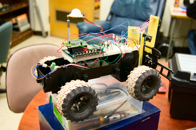
For convenience, a New Bright toy RC car was purchased and disassembled. The motors and wheels were already pre-mounted onto the chassis. Motor controllers could easily control the motors to drive and steer the vehicle. On the chassis, slots above the wheel wells were large enough to house motor controllers while the center of the chassis provided enough room to include a small breadboard and the microcontroller. All wires were shortened to the shortest length possible to reduce clutter.Sensor and Alarm Placement
The sensors, which guided car control, were strategically mounted in front and above the car. This increased visibility of the sensors. Three distance sensors were used to detect obstacles: a left-, a center-, and a right-side sensor was used to determine steering of the vehicle. A front-mounted sensor sought motion as the car was stopped. Once motion was detected, the car promptly sounded the piezo buzzer alarm after determining that the motion was legitimate.
Power Supply
The battery box beneath the car provided additional convenience. It housed five 1.5-volt AA batteries that supplied up to 7.5 volts in series. This power supply provided enough power to run all of the components of this project. Whenever existing batteries began to run low on power, new batteries could be swapped into place easily. The following list describes the power requirements of each part used:
| Part | Voltage Range | Source |
|---|---|---|
| Distance Sensors (Parallel) | +5V | Microcontroller Pin |
| LPC2148 Microcontroller | +7V to +20V | Battery Pack |
| Motion Sensors | +5V to +12V | Battery Pack |
| Motor Controllers | +7V to +30V | Battery Pack |
| Piezo Buzzer | +3V to +6V | Microcontroller Pin |
Motion Sensor
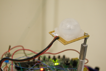
The passive infrared sensor measures changes in the environment, using heat as an indicator. It signals the pin low when it detects a change in heat. Three pins, with associated wire colorings, are used: red for voltage source, brown for ground, and black for alarm signal. The alarm signal can be connected to any pin on the microcontroller that can handle GPIO. Also, a pull up resistor is needed on the pin to GPIO. The pull up resistor is required because the sensor alarm pin is an open collector. Without this resistor, the value of the alarm will merely fluctuate between low and high constantly. Shown below are the connections between the microcontroller and the alarm:
| Microcontroller | Motion Sensor |
|---|---|
| VCC (7.5V) | VCC (7.5V) |
| GND | GND |
| P0.10 | Alarm (AL) |
Alarm
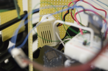
The 75dB alarm can handle up to 6 volts of power. A quick test on the voltage generator showed that 3 volts, which comes from a GPIO output pin, was plenty to create an audible sound.
| Microcontroller | Alarm |
|---|---|
| P0.12 | VCC (3.3V) |
| GND | GND |
Distance Sensor
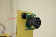
The SRF02 ultrasonic range finder (distance sensor) can operate through serial mode or I2C mode. This device carries five pins: +5V VCC, SDA, SCL, Mode, and Ground. Since the I2C mode is used, the mode pin doesn’t need to connect to anything. The SCL and SDA lines are connected to the pins that support SCL0 and SDA0 on the microcontroller. These pins also need a pair of resistors because I2C is an open collector.
| Microcontroller | Distance Sensor |
|---|---|
| Regulator (+5V) | VCC (+5V) |
| P0.2 | SDA |
| P0.3 | SCL |
| GND | GND |
5A Motor Controllers
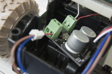
The motor controllers were used to adjust speed on the motors. The controllers maintain a continuous 5A current while applying voltage. Interfacing the motor controllers requires three pins: PWM, direction, and ground. Pins were initiated prior to using the motor controllers. The rear motor used PWM while the front motor used GPIO in place of PWM.
| Microcontroller | Front Motor Controller |
|---|---|
| VCC (7.5v) | VCC (7.5v) |
| P0.9 | PWM |
| P0.6 | DIR |
| GND | GND |
| Microcontroller | Rear Motor Controller |
|---|---|
| VCC (7.5v) | VCC (7.5v) |
| P0.7 | PWM |
| P0.8 | DIR |
| GND | GND |
Switch
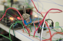
A single-pole double-throw switch was added to the board to quickly connect and disconnect power to the system.
Software Design
Using FreeRTOS
FreeRTOS, a real-time operating system, was used to program the hardware used on the vehicle. FreeRTOS mainly uses C while allowing for some expansion into C++. Its support for tasks and semaphores made it a convenient platform for writing and implementing software for this project. Furthermore, FreeRTOS requires a small amount of memory while running tasks quickly and efficiently.
Several labs built using FreeRTOS were completed prior to starting this project, which contributed to a good understanding of the FreeRTOS system. The basic coding structure used for the labs also served as the basic coding framework for the Evil Watchdog.
Part-by-part Expansion
Once all the necessary parts were collected, each part received its own dedicated piece of code and its own testing before becoming integrated with the other parts used for the car. Intuitively, the motor controllers were selected as the first parts for writing code, because the vehicle's movement depended entirely on the motors and wheels. Each motor controller can regulate the speed at which the attached wheels spin, through the use of pulse-width modulation (PWM). Looking at the car, only the rear wheels need speed control. It was not necessary to implement PWM on the front wheels because those wheels are used for steering and simply require steering extreme left, extreme right, or straight, thanks to the car's small size. The rear wheels were controlled through PWM, and the front wheels through GPIO.
Pulse-width Modulation
Pulse-width modulation, or PWM, allows a motor controller to govern the speed at which a motor turns. Two key features of a PWM driver are the frequency, which determines how often a cycle repeats, and the duty cycle, which controls the speed of the motor spinning. The PWM driver allows the microcontroller to send out pulses based on the frequency and duty cycle settings, similar to a person flapping a rope up and down with the other end of the rope attached to a wall. By changing the PWM's frequency, the vehicle's rear motors could be slowed down or sped up. The board pins were set up accordingly:
- Reset P0.7
- Assign P0.7 for PWM2
- Assign P0.8 for direction (GPIO)
- Set P0.8 direction as output
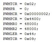
The PWM driver was initialized, too:
The PWM registers had to be set accordingly. Looking at the LPC2148 datasheet, the registers shown above were configured:
- PWMTCR: Timer control. Reset first with bit 1.
- PWMPR: Prescale. Increments every PCLK cycle. Set to zero.
- PWMMCR: Match control. Control if interrupt is generated. Will reset on MR0.
- PWMPCR: Control. Enables PWM in single-edge mode.
- PWMMR0: PWM period. Set to 48000 Hz to match CPU.
- PWMMR2: Duty cycle/PWM width. Compared to PWMMR0. Output duty is inversely related to PWMMR0.
- PWMLER: Latch enable. Latch in all PWMMRx.
- PWMTCR: Timer control (again). Enable counter with bits 0 and 3.
With the PWM registers initialized, the duty cycle could later be modified to change motor speed. PWMMR2 was used in this case. Therefore, if a change in motor speed was necessary, PWMMR2 could be set inclusively between 0 and 48000 to change the duty cycle.
Steering Control
At first, it seemed a good idea that PWM be used on the front motor controller. After attempting to establish PWM on the steering side of the car, Preet recommended that GPIO could handle the steering job just as well. The pins had to be initialized first:
- Assign P0.9 as GPIO for controlling full or zero power
- Set P0.9 as output
- Assign P0.6 as GPIO for direction
- Set P0.6 as output
The most difficult part of using GPIO for steering was mapping out which voltages corresponded to which steering direction. The motor controller could turn extreme left, extreme right, or stayed straight. To help determine the directions, a handy table was created:
| Controller | GPIO Low (0V) | GPIO High (+3.3V) |
|---|---|---|
| PWM Pin | Power | No Power |
| DIR Pin | Left | Right |
Changing the motor between go/stop and left/right was done by either setting the P0.6 or P0.9 pins, respectively, to 1 or 0 using IOSET0 and IOCLR0. Using the help of LEDs, the correct directions and power distribution was mapped for the motor controller. It was interesting to note that to get back to center, a change of direction had to take place. For example, if the car was heading left, it had to be steered back to the right to "release" the left steering before returning to center position.
Distance Sensors: I2C
The distance sensors were designed for use on the I2C or serial buses. Based on pin availability and software convenience, I2C was used to gather distance information from the sensors. The next question was: How would the microcontroller distinguish between the three sensors? A glance at the technical specifications provided the solution. Each sensor was equipped with a handy LED that flashed its address in a recognizable sequence. Each sequence was one long flash, accompanied by a number of short flashes. The short flashes represented the difference in the current address from 0xE0 in increments of 0x02, up to 15 short flashes. Legal addresses ranged from 0xE0 to 0xFE.
By comparing the sequence emitted, a programmer could determine the sensor's set address. Also, its address could be altered to allow the I2C to accommodate additional sensors, though each sensor must be programmed individually, one at a time. This sequence was used to set each sensor:
- Get sensor address
- Send 0xA0 to address
- Send 0xAA to address
- Send 0xA5 to address
- Send new address to address
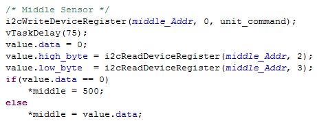
For convenience, the following addresses were selected for the sensors: 0xE2 for the left sensor, 0xE4 for the center, and 0xE6 for the right.
An I2C call is made when the microcontroller wants to retrieve information from the distance sensors. The I2C bus is shared, and the program allocates enough time to release slave devices when required. The "unit_command" variable was set to 81 to force the sensor to measure distances in centimeters. If the user wants to opt for measurements in inches, the variable can simply be changed to 80.
Locations 2 and 3 hold the newest reading in a 16-bit unsigned integer format. Through high and low bytes, the sensor readings could be retrieved. The datasheet warns that it is best to give a minimum of 65 milliseconds for the pings to fade away properly. In the code, a 75 ms vTaskDelay was added to accommodate for the wait.
Motion Sensor
As with the front motor, the pins for the motion sensor were initialized:
- Assign P0.10 as GPIO
- Set P0.10 as input
A GPIO input pin was designated on the microcontroller to interact with the motion sensor. The motion sensor dropped its voltage to zero whenever motion was detected, which registered sufficient data for the pin on the board.
To check for motion, the code looked for a zero on the P0.10 pin.
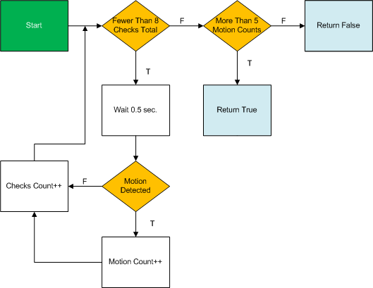
The system surveyed for motion eight times in 500 millisecond intervals. When motion was detected in five out of those eight intervals, the alarm was sounded. This prevented false alarms from occurring, in the event that stray, non-legitimate motion came across the sensor's environment. This diagram shows the motion surveying method:
Alarm Triggering
One more GPIO pin was used for the alarm:
- Assign P0.12 as GPIO
- Set P0.12 as output
Whenever the pin was set active, the alarm rang. Turning the alarm on and off was based on whether motion was detected. Using IOSET and IOCLR to change the pin to 1 and 0 was done through functions.
Loading the Software
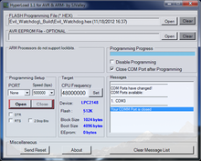
Once the program was built and compiled, a .hex file was generated, which contained the program that will be read by the microcontroller. The .hex file was transferred from computer to microcontroller through a USB cable. HyperLoad 1.1 was run on the programming computer to interact with the microcontroller via USB. Setting up HyperLoad 1.1 included changing the COM port speed to 500000 bps and target CPU frequency to 48000000. The .hex file was chosen, the proper port was opened, and the file was transferred.Software Implementation
Task Flowchart
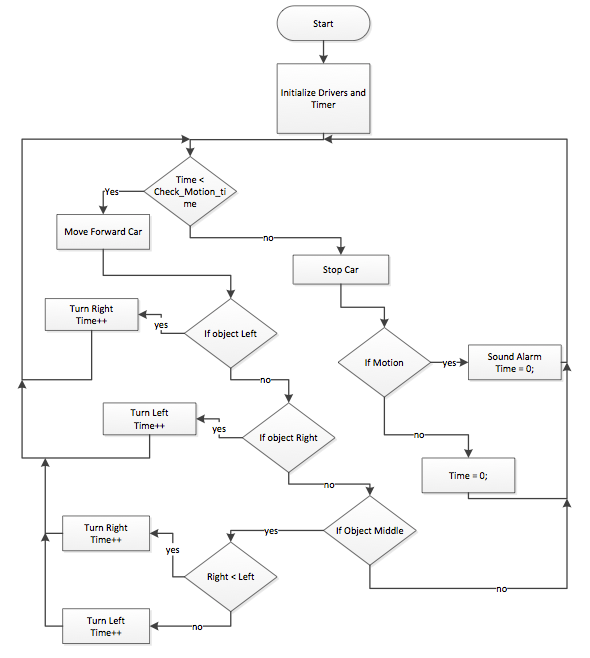
The program was designed to run by employing tasks that handled sensor readings and appropriate outputs. A "drive" task was assigned to handle vehicular driving, and a "SensorValue" task was assigned to continuously capture data from the distance and motion sensors. When combined, the tasks worked to drive the vehicle safely through a path. The below illustrates how the general function of the program used to control the Evil Watchdog:
A timer, in conjunction with the vTaskDelay command, allowed the microcontroller to switch between driving mode and motion sensing mode. It is important to note that scanning for motion while the vehicle is moving is pointless. Unless there was a way to filter out motion caused by the vehicle, it was better to stop the vehicle briefly to look for motion before continuing driving.
Testing
Motor Controllers
The motor controllers were the first components tested once the PWM driver was written. At first, the assumption was that setting PWMMR2 to zero meant a full stop. That became untrue as the dog tried to run away at full speed. Once it was realized that a higher duty cycle corresponded to slower motion, the rear controller was successfully configured. The front motor controller was tested too. The main difficulty was in mapping out the voltage levels and voltage directions to see whether they corresponded to left, right, or center steering. Using LEDs helped figure out the mappings. An interesting point to note is that to return to center steering via GPIO, a change in steering direction must take place.
Distance Sensors
Prior to implementation, the distance sensors were placed on a breadboard to verify the accuracy of their readings. The sensors featured measurements at the centimeter level, allowing for more detailed integer readings compared to readings in inches. During testing, a tape measure was used to confirm sensor measurements. The error found was no more than 3-5% at distances up to 250 cm, which showed that the sensors were highly reliable for providing the vehicle's sight.
Motion Sensor
The motion sensor was tested independently with a voltage generator and a digital multimeter. During everything, the multimeter showed that the sensor was very sensitive to nearby movement. Another observation was that when higher voltage was applied, the motion sensor captured motion from further distances. Lastly, it was noted that there was a delay between returning from "motion detected" to "no motion detected." It turns out that the alarm signal stayed low when detecting motion for about 3 seconds before returning to high. An open collector circuit caused the delays observed.
Alarm
Because the alarm worked with different voltages, it was tested on a voltage generator before being placed in the car. 3.3 volts was enough to supply an audible tone.
When working with registers, it is important to double-check the code to see whether logic is written properly. Using IOSET and IOCLR, for instance, may seem easy and straightforward. However, they can easily become mixed up when a boolean checker is thrown into the mix. At one point during testing, the alarm rang when motion was sighted, and continued to ring forever. The suspect was an IOSET assignment that was instead supposed to be IOCLR. Once that was repaired, the dog ran happily again.
The Entire Dog
Once all the components were stitched and strapped onto the dog, the canine was released into the wild (the Engineering building hallways). It ran freely and occasionally bumped into walls. The distance sensor thresholds were modified to allow extra space between the dog and its nearest obstacles. At one point, steering froze for no apparent reason. A close examination revealed that super glue holding the distance sensor posts had dripped onto the front axle, preventing the dog from making turns. Small corrections were made to the code whenever the vehicle did not behave as expected. For example, if the rear wheels spun too fast, the PWMMR2 setting was decreased.
Technical Challenges
Battery Life
By far, the battery pack was the most vulnerable component in keeping the Evil Watchdog alive. Only five 1.5-volt AA batteries powered the entire system. Possible solutions to this problem were to either use batteries with longer lifespans or to use rechargeable batteries to avoid wasting single-use cells. During testing, a variable-voltage DC power supply, grabbing power from a wall outlet, was used to power the project. This saved battery power later needed for demoing. One key observation was that the system consumed the most power with the rear motors spinning at full speed, allowing the motor controller to consume a full 5 amps. This was devastating to the batteries. When the rear motors were set to run at only 20% of maximum speed, the system as a whole consumed a more generous current of 0.3 amps, as shown in the picture at right.
Distance Sensor Placement
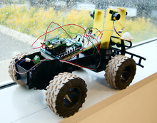
It is a good idea to keep the side distance sensors pointing 45 degrees away from the center sensor instead of perpendicular to it. Suggested by Preet, this allows the car to see more of its path ahead while maintaining some peripheral vision. In early stages of testing, the distance sensors were placed perpendicular to each other, as shown in the picture.
Motion Sensor Polling
The motion sensor is highly sensitive. It can detect slight movements in its environment. To avoid false alarms, the program was modified to force the motion sensor to detect continuous movement before it decides to ring the alarm. By doing so, the system ignored sudden movements that were assumed to be non-dangerous.
Vehicle Weight
The original toy car was designed to carry a lightweight circuit board that received RF signals to control the motors. When the car was torn apart and new components were added for this project, the amount of weight placed on the wheels rapidly increased. Additional weight required extra torque from the wheels to move the carried load, which drained the AA alkaline batteries much more quickly. The best way to alleviate this problem was to eliminate excess weight and to select the lightest available parts to be placed on the vehicle.
Conclusion
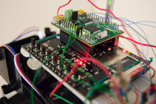
The journey from learning how to program the LPC2148 to creating a fully working autonomous “watchdog” was extremely rewarding. Through Preet’s guidance in lab, it became apparent that the LPC2148 contains plenty of potential for hands-on projects. Seeing classmates build their own creative projects showed the power and versatility of the LPC2148. Even though this project was built on a small scale, it built a foundation for a better understanding of embedded systems’ impact in the real world.
The main obstacle (no pun intended) for this project was delivering work according to schedule. While every team member had additional projects to complete, the proposed schedule ensured that the project was completed in a timely manner to prevent last-minute exhaustion. Many thanks go to Preet for encouraging the entire CmpE 146 class to adhere to their schedules, and this was certainly true for the creators of this project.
After project completion, it became apparent that good programming and understanding impacts how the project evolves from stage to stage. It was ideal to prepare every part until it functions properly before integrating them with additional parts. When individual parts are prepared well with useful program functions, fewer errors will occur down the road.
In addition, good communication was crucial in moving forward in not just this project, but in any project or lab. Sometimes, code and datasheets can become confusing. It may take one hour for one person to solve a problem, whereas asking for help from a more knowledgeable person can produce a solution in 10 minutes. The main challenge with working in groups was to find common times to gather to resume work on the Evil Watchdog project. E-mails and phone calls were not always the fastest ways to keep everyone on track. Working at the same table allowed faster progress than long-distance collaboration.
Creating the Evil Watchdog and taking the CmpE 146 lab with Preet was a memorable experience. Through countless tests, compilation errors, and hand-on experience with the LPC2148, better knowledge of embedded systems was gained. This project will serve as a big achievement that will be reflected on for years to come.
Finished Product
References
Thanks To...
- Dr. Haluk Özemek: Lecturer
- Preet Kang: Lab Instructor
Datasheets
- [1] Philips Semiconductors. LPC214x datasheet. August 2006.
- [2] Robot Electronics. SRF02 ultrasonic range finder datasheet. Retrieved from http://www.robot-electronics.co.uk/htm/srf02techI2C.htm

