Difference between revisions of "F16: Kasper"
Proj user18 (talk | contribs) (→Team Schedule) |
Proj user18 (talk | contribs) (→Team Schedule) |
||
| Line 96: | Line 96: | ||
| | | | ||
|- | |- | ||
| − | ! scope="row"| 6 | + | ! scope="row" colspan="2"| 6 |
| 10/25/2016 | | 10/25/2016 | ||
| | | | ||
Revision as of 23:17, 20 October 2016
Contents
Project Title
Self Driving Car
Abstract
This project implements a self-driving car.
Objectives & Introduction
Objective of this project is to create a self driving car
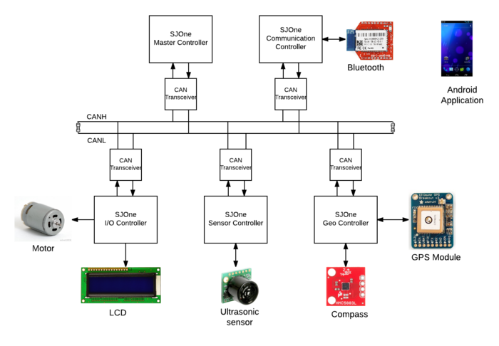
System Block Diagram
Team Members & Responsibilities
We have used five controllers
- Sensor Controller
- Shruthi Narayan
- Rimjhim Ghosh
- Motor & I/O Controller
- Prashant Aithal
- Chethan Keshava
- Geographical Controller
- Ankit Gandhi
- Master Controller
- Aajna Karki
- Spoorthi Mysore Shivakumar
- Communication Bridge Controller
- Bharat Khanna
- Shantanu Vasishtha
Team Schedule
| Sl No. | Start Date | End Date | Task | Status | Actual Completion Date | |
|---|---|---|---|---|---|---|
| 1 | 09/20/2016 | 09/27/2016 |
|
Completed | 09/27/2016 | |
| 2 | 09/28/2016 | 10/04/2016 |
|
Completed | 10/04/2016 | |
| 3 | 10/05/2016 | 10/11/2016 |
|
Completed | 10/11/2016 | |
| 4 | 10/12/2016 | 10/18/2016 |
|
Completed | 10/18/2016 | |
| 5 | 10/19/2016 | 10/25/2016 |
|
Upcoming Task | ||
| 6 | 10/25/2016 |
CAN COMMUNICATION DEMO |
Upcoming Task | |||
| 7 | 10/26/2016 | 11/07/2016 |
|
Upcoming Task | ||
| 8 | 11/08/2016 |
PROJECT PROTOTYPE DEMO |
Upcoming Task | |||
| 9 | 11/08/2016 | 11/15/2016 |
|
Upcoming Task | ||
| 10 | 11/16/2016 | 11/29/2016 |
|
Upcoming Task | ||
| 11 | 11/29/2016 |
PROJECT PROTOTYPE DEMO 2 |
Upcoming Task | |||
| 12 | 11/29/2016 | 12/06/2016 |
|
Upcoming Task | ||
| 13 | 12/07/2016 | 12/15/2016 |
|
Upcoming Task | ||
| 14 | 12/17/2016 |
FINAL PROJECT DEMO |
Upcoming Task | |||
| 14 | 12/20/2016 |
|
Upcoming Task | |||
Parts List & Cost
| Item# | Part Desciption | Vendor | Qty | Cost $ |
|---|---|---|---|---|
| 1 | RC Car | From Preet | 1 | 0 |
| 2 | SJOne board | Preet | 5 | 80 |
| 3 | GPS Module | From Preet | 1 | 40 |
| 4 | Triple Axis Magnetometer (Compass) | Sparkfun | 1 | 15 |
| 5 | Bluetooth Module | Sparkfun | 1 | 24.95 |
| 6 | LCD screen | Adafruit | 1 | 24.95 |
Sensor Controller
Team Members & Responsibilities
- Shruthi Narayan
- Rimjhim Ghosh
Schedule
| SI No. | Start Date | End Date | Task | Status | Actual Completion Date |
|---|---|---|---|---|---|
| 1 | 10/5/2016 | 10/11/2016 |
|
Completed | 10/9/2016 |
| 2 | 10/12/2016 | 10/18/2016 |
|
In Progress | |
| 3 | 10/19/2016 | 10/25/2016 |
|
Upcoming Task | |
| 4 | 10/26/2016 | 11/1/2016 |
|
Upcoming Task | |
| 5 | 11/2/2016 | 11/8/2016 |
|
Upcoming Task | |
| 6 | 11/9/2016 | 11/15/2016 |
|
Upcoming Task | |
| 7 | 11/16/2016 | 11/22/2016 |
|
Upcoming Task | |
| 8 | 11/23/2016 | 11/29/2016 |
|
Upcoming Task | |
| 9 | 11/30/2016 | 12/6/2016 |
|
Upcoming Task | |
| 10 | 12/7/2016 | 12/17/2016 |
|
Upcoming Task |
Design & Implementation
The design section can go over your hardware and software design. Organize this section using sub-sections that go over your design and implementation.
Hardware Design
Discuss your hardware design here. Show detailed schematics, and the interface here.
Hardware Interface
In this section, you can describe how your hardware communicates, such as which BUSes used. You can discuss your driver implementation here, such that the Software Design section is isolated to talk about high level workings rather than inner working of your project.
Software Design
Show your software design. For example, if you are designing an MP3 Player, show the tasks that you are using, and what they are doing at a high level. Do not show the details of the code. For example, do not show exact code, but you may show psuedocode and fragments of code. Keep in mind that you are showing DESIGN of your software, not the inner workings of it.
Implementation
This section includes implementation, but again, not the details, just the high level. For example, you can list the steps it takes to communicate over a sensor, or the steps needed to write a page of memory onto SPI Flash. You can include sub-sections for each of your component implementation.
Testing & Technical Challenges
Describe the challenges of your project. What advise would you give yourself or someone else if your project can be started from scratch again? Make a smooth transition to testing section and described what it took to test your project.
Motor & I/O Controller
Team Members & Responsibilities
- Chethan Keshava
- Prashant Aithal
Schedule
| SI No. | Start Date | End Date | Task | Status | Actual Completion Date | |
|---|---|---|---|---|---|---|
| 1 | 09/27/2016 | 10/04/2016 |
|
Completed | 10/04/2016 | |
| 2 | 10/04/2016 | 10/11/2016 |
|
Completed | 10/07/2016 | |
| 3 | 10/11/2016 | 10/18/2016 |
|
Upcoming Task | ||
| 4 | 10/18/2016 | 10/25/2016 |
|
Upcoming Task | ||
| 5 | 10/25/2016 | 11/1/2016 |
|
Upcoming Task | ||
| 6 | 11/1/2016 | 11/15/2016 |
|
Upcoming Task | ||
| 7 | 11/15/2016 | 11/28/2016 |
|
Upcoming Task | ||
| 8 | 11/28/2016 | 12/05/2016 |
|
Upcoming Task |
Design & Implementation
The design section can go over your hardware and software design. Organize this section using sub-sections that go over your design and implementation.
Hardware Design
Discuss your hardware design here. Show detailed schematics, and the interface here.
Hardware Interface
In this section, you can describe how your hardware communicates, such as which BUSes used. You can discuss your driver implementation here, such that the Software Design section is isolated to talk about high level workings rather than inner working of your project.
Software Design
Show your software design. For example, if you are designing an MP3 Player, show the tasks that you are using, and what they are doing at a high level. Do not show the details of the code. For example, do not show exact code, but you may show psuedocode and fragments of code. Keep in mind that you are showing DESIGN of your software, not the inner workings of it.
Implementation
This section includes implementation, but again, not the details, just the high level. For example, you can list the steps it takes to communicate over a sensor, or the steps needed to write a page of memory onto SPI Flash. You can include sub-sections for each of your component implementation.
Testing & Technical Challenges
Describe the challenges of your project. What advise would you give yourself or someone else if your project can be started from scratch again? Make a smooth transition to testing section and described what it took to test your project.
Geographical Controller
Team Members & Responsibilities
- Ankit Gandhi
Schedule
| SI No. | Start Date | End Date | Task | Status | Actual Completion Date |
|---|---|---|---|---|---|
| 1 | 09/28/2016 | 10/4/2016 |
|
Completed | 10/6/2016 |
| 3 | 10/5/2016 | 10/11/2016 |
|
Completed | 10/10/2016 |
| 4 | 10/12/2016 | 10/18/2016 |
|
InProgress | |
| 5 | 10/19/2016 | 10/25/2016 |
|
Upcoming Task | |
| 6 | 10/26/2016 | 11/01/2016 |
|
Upcoming Task | |
| 7 | 11/02/2016 | 11/08/2016 |
|
Upcoming Task | |
| 8 | 11/09/2016 | 12/05/2016 |
|
Upcoming Task |
Design & Implementation
The design section can go over your hardware and software design. Organize this section using sub-sections that go over your design and implementation.
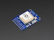
GPS Module
The breakout is built around the MTK3339 chipset, a no-nonsense, high-quality GPS module that can track up to 22 satellites on 66 channels
- -165 dBm sensitivity, 10 Hz updates, 66 channels
- 5V friendly design and only 20mA current draw
- RTC battery-compatible
- Internal patch antenna + u.FL connector for external active antenna
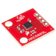
The Compass Module - HMC5883L
Compass module is based on Honeywell’s HMC5883L. <br\> When current flows through a wire, a magnetic field is created. This is the basic principle behind electromagnets. This is also the principle used to measure magnetic fields with a magnetometer. The direction of Earth's magnetic fields affects the flow of electrons in the sensor, and those changes in current can be measured and calculated to derive a compass heading.
The features of HMC5883L are:
- Simple I2C interface
- 2.16-3.6VDC supply range
- Low current draw
- 5 milli-gauss resolution
Hardware Design
Discuss your hardware design here. Show detailed schematics, and the interface here.
Hardware Interface
In this section, you can describe how your hardware communicates, such as which BUSes used. You can discuss your driver implementation here, such that the Software Design section is isolated to talk about high level workings rather than inner working of your project.
Software Design
Show your software design. For example, if you are designing an MP3 Player, show the tasks that you are using, and what they are doing at a high level. Do not show the details of the code. For example, do not show exact code, but you may show psuedocode and fragments of code. Keep in mind that you are showing DESIGN of your software, not the inner workings of it.
Implementation
This section includes implementation, but again, not the details, just the high level. For example, you can list the steps it takes to communicate over a sensor, or the steps needed to write a page of memory onto SPI Flash. You can include sub-sections for each of your component implementation.
Testing & Technical Challenges
Describe the challenges of your project. What advise would you give yourself or someone else if your project can be started from scratch again? Make a smooth transition to testing section and described what it took to test your project.
Communication Bridge Controller
Team Members & Responsibilities
- Bharat Khanna
- Shantanu Vashishtha
Schedule
| SI No. | Start Date | End Date | Task | Status | Actual Completion Date |
|---|---|---|---|---|---|
| 1 | 09/20/2016 | 09/27/2016 |
|
Completed | 09/27/2016 |
| 2 | 09/28/2016 | 10/4/2016 |
|
Completed | 10/9/2016 |
| 3 | 10/5/2016 | 10/11/2016 |
|
In Progress | |
| 4 | 10/12/2016 | 10/18/2016 |
|
Upcoming Task | |
| 5 | 10/19/2016 | 10/25/2016 |
|
Upcoming Task | |
| 6 | 10/26/2016 | 11/08/2016 |
|
Upcoming Task | |
| 7 | 11/9/2016 | 11/20/2016 |
|
Upcoming Task | |
| 8 | 11/21/2016 | 12/05/2016 |
|
Upcoming Task |
Design & Implementation
The design section can go over your hardware and software design. Organize this section using sub-sections that go over your design and implementation.
Hardware Design
Discuss your hardware design here. Show detailed schematics, and the interface here.
Hardware Interface
In this section, you can describe how your hardware communicates, such as which BUSes used. You can discuss your driver implementation here, such that the Software Design section is isolated to talk about high level workings rather than inner working of your project.
Software Design
Show your software design. For example, if you are designing an MP3 Player, show the tasks that you are using, and what they are doing at a high level. Do not show the details of the code. For example, do not show exact code, but you may show psuedocode and fragments of code. Keep in mind that you are showing DESIGN of your software, not the inner workings of it.
Implementation
This section includes implementation, but again, not the details, just the high level. For example, you can list the steps it takes to communicate over a sensor, or the steps needed to write a page of memory onto SPI Flash. You can include sub-sections for each of your component implementation.
Testing & Technical Challenges
Describe the challenges of your project. What advise would you give yourself or someone else if your project can be started from scratch again? Make a smooth transition to testing section and described what it took to test your project.
Master Controller
Team Members & Responsibilities
- Aajna Karki
- Spoorthi Mysore Shivakumar
Schedule
| SI No. | Start Date | End Date | Task | Status | Actual Completion Date |
|---|---|---|---|---|---|
| 1 | 09/26/2016 | 10/05/2016 |
|
Completed | 10/05/2016 |
| 2 | 10/06/2016 | 10/18/2016 |
|
Completed | 10/18/2016 |
| 3 | 10/19/2016 | 10/25/2016 |
|
Upcoming Task | |
| 4 | 10/26/2016 | 11/05/2016 |
|
Upcoming Task | |
| 5 | 11/06/2016 | 11/15/2016 |
|
Upcoming Task | |
| 6 | 11/16/2016 | 11/25/2016 |
|
Upcoming Task | |
| 7 | 11/25/2016 | 12/05/2016 |
|
Upcoming Task | |
| 9 | 12/06/2016 | 12/15/2016 |
|
Upcoming Task |
Design & Implementation
The design section can go over your hardware and software design. Organize this section using sub-sections that go over your design and implementation.
Hardware Design
Discuss your hardware design here. Show detailed schematics, and the interface here.
Hardware Interface
In this section, you can describe how your hardware communicates, such as which BUSes used. You can discuss your driver implementation here, such that the Software Design section is isolated to talk about high level workings rather than inner working of your project.
Software Design
Show your software design. For example, if you are designing an MP3 Player, show the tasks that you are using, and what they are doing at a high level. Do not show the details of the code. For example, do not show exact code, but you may show psuedocode and fragments of code. Keep in mind that you are showing DESIGN of your software, not the inner workings of it.
Implementation
This section includes implementation, but again, not the details, just the high level. For example, you can list the steps it takes to communicate over a sensor, or the steps needed to write a page of memory onto SPI Flash. You can include sub-sections for each of your component implementation.
Testing & Technical Challenges
Describe the challenges of your project. What advise would you give yourself or someone else if your project can be started from scratch again? Make a smooth transition to testing section and described what it took to test your project.
My Issue #1
Discuss the issue and resolution.
Conclusion
Conclude your project here. You can recap your testing and problems. You should address the "so what" part here to indicate what you ultimately learnt from this project. How has this project increased your knowledge?
Project Video
Upload a video of your project and post the link here.
Project Source Code
References
Acknowledgement
Any acknowledgement that you may wish to provide can be included here.
References Used
List any references used in project.
Appendix
You can list the references you used.


