Difference between revisions of "S16: Sound Buddy"
Proj user12 (talk | contribs) (→The Sender Board) |
Proj user12 (talk | contribs) (→References) |
||
| (149 intermediate revisions by the same user not shown) | |||
| Line 1: | Line 1: | ||
| − | |||
| − | |||
| − | |||
| − | |||
| − | |||
| − | |||
| − | |||
| − | |||
| − | |||
| − | |||
| − | |||
| − | |||
== Project Title == | == Project Title == | ||
| − | [[File:SP16_Sound_Buddy_Logo_1.jpg| | + | [[File:CMPE244 SP16_Sound_Buddy_Logo_1.jpg|600px|center]] |
== Abstract == | == Abstract == | ||
| Line 22: | Line 10: | ||
Developed with amazing technologies such as the Nordic transceiver device, MP3 decoder, SJOne board, and the powerful FreeRTOS, Sound Buddy comes to life! | Developed with amazing technologies such as the Nordic transceiver device, MP3 decoder, SJOne board, and the powerful FreeRTOS, Sound Buddy comes to life! | ||
| + | |||
| + | Walk through the design and development of the prototype for this exciting project. | ||
== Objectives == | == Objectives == | ||
| Line 39: | Line 29: | ||
=== Team Members - Responsibilities === | === Team Members - Responsibilities === | ||
| − | * Brigitte De Leon - Tell everyone what to do | + | * [https://www.linkedin.com/in/brigittedeleon Brigitte De Leon] - Tell everyone what to do |
* Catherine Gamboa - Be early to all the meetings | * Catherine Gamboa - Be early to all the meetings | ||
* Hudo Assenco - Wake up | * Hudo Assenco - Wake up | ||
| Line 106: | Line 96: | ||
== Parts List & Cost == | == Parts List & Cost == | ||
| + | The parts tabulated below are those necessary to complete the project. It does not reflect the acutal parts used during testing also. During testing, extra devices were used to debug and replace damaged devices. Those dead components lay peacefully in our project graveyard. | ||
{| class="wikitable" | {| class="wikitable" | ||
|- | |- | ||
| Line 126: | Line 117: | ||
| $5.94 | | $5.94 | ||
|- | |- | ||
| − | ! scope="row"| | + | ! scope="row"| 2 |
| Audio Jack 3.5mm | | Audio Jack 3.5mm | ||
| − | | | + | | 2 |
| $1.50 | | $1.50 | ||
| $4.50 | | $4.50 | ||
| Line 141: | Line 132: | ||
| Printed Circuit Boards | | Printed Circuit Boards | ||
| 2 | | 2 | ||
| − | | $-.-- | + | | $--.-- |
| $32.05 | | $32.05 | ||
|- | |- | ||
| Line 164: | Line 155: | ||
! scope="row"| 9 | ! scope="row"| 9 | ||
| Screw Terminals 3.5mm Pitch(2-Pin) | | Screw Terminals 3.5mm Pitch(2-Pin) | ||
| − | | | + | | 4 |
| $0.95 | | $0.95 | ||
| − | | $ | + | | $3.80 |
|- | |- | ||
! scope="row"| 10 | ! scope="row"| 10 | ||
| Line 176: | Line 167: | ||
! scope="row"| 11 | ! scope="row"| 11 | ||
| Resistors | | Resistors | ||
| − | | | + | | 20 |
| $0.19 | | $0.19 | ||
| − | | $ | + | | $3.80 |
|- | |- | ||
! scope="row"| 12 | ! scope="row"| 12 | ||
| Capacitors | | Capacitors | ||
| 120 | | 120 | ||
| − | | $--- | + | | $--.-- |
| $20.11 | | $20.11 | ||
|- | |- | ||
| Line 199: | Line 190: | ||
|- | |- | ||
! scope="row"| 15 | ! scope="row"| 15 | ||
| + | | LEDs | ||
| + | | 8 | ||
| + | | $0.20 | ||
| + | | $1.60 | ||
| + | |- | ||
| + | ! scope="row"| 16 | ||
| SJOne Board | | SJOne Board | ||
| 3 | | 3 | ||
| $80.00 | | $80.00 | ||
| $240.00 | | $240.00 | ||
| + | |- | ||
| + | ! scope="row"| 17 | ||
| + | | 9V batteries | ||
| + | | 2 | ||
| + | | $-.-- | ||
| + | | $8.00 | ||
|- | |- | ||
! scope="row"| | ! scope="row"| | ||
| Line 208: | Line 211: | ||
| | | | ||
| $-.-- | | $-.-- | ||
| − | | $ | + | | $373.11 |
|- | |- | ||
|} | |} | ||
| Line 219: | Line 222: | ||
=== Hardware Design === | === Hardware Design === | ||
| − | + | The hardware design was limited by the pins that the SJOne board provided. Luckily, this was not an issue for Sound Buddy. The protocols used were SPI/SSP and I2C so the number of pins were already availble for use of communication. A PCB was designed to house the MP3 decoder circuit. This PCB is mounted right on top of the SJOne board enclosing the unit as one functional device. | |
| − | |||
| − | |||
| + | ==== System Design ==== | ||
{| | {| | ||
| − | + | |- | |
| − | + | | [[File:CMPE244 S16 Sound Buddy System Design.jpg|400px|left|thumb]] | |
| − | + | | Sound Buddy's core component is the SJOne board. For more information about the SJOne board click this link <span class="plainlinks">[http://www.socialledge.com/sjsu/index.php?title=SJ_One_Board SJOne board]</span> or visit the main page of this Wiki. | |
| − | + | ||
| − | + | Its system is composed of a sender device and one or more receiver devices. An MP3 file will be stored on the micro SD card which will be inserted into the sender's SD slot. The sender device will read and send out the raw MP3 data over the Nordic wireless protocol. Each device uses the built-in Nordic wireless transceiver which allows for one-way communication from the sender to the receiver(s). | |
| + | |||
| + | Plugged onto each on the other receivers is the MP3 decoder circuit. The receiver device will be waiting for the MP3 data. Once it detects data has been sent over, it begins to process the data by sending it out to the MP3 decoder. The MP3 decoder translates the raw data and sends it out to the onboard DAC. The DAC converts the raw data into audible signals that get pushed out to the audio0 jack where the speakers play the music. | ||
| + | |||
| + | Now, that was a mouthful. Let's dive deeper into each of the component design. | ||
|} | |} | ||
<br><br> | <br><br> | ||
| + | |||
==== Sender Board ==== | ==== Sender Board ==== | ||
| − | + | {| | |
| + | |- | ||
| + | | The sender board uses the SD card and the [https://www.sparkfun.com/datasheets/Components/SMD/nRF24L01Pluss_Preliminary_Product_Specification_v1_0.pdf Nordic wireless transceiver] onboard. Using the SPI protocol, the SD card will be enabled for I/O purposes. There is a total of four wires utilized namely the SCK, MOSI, MISO, and CS. These wires are connected internally and the data transfer and chip select are handled by the driver and application code. | ||
| + | |||
| + | Similar to the SD card, the Nordic transceiver uses SPI protocol to send and receive data. This, too, is hooked up internally and the initialization and function are done through coding. The additional hardware part attached to the SJOne board is the 2.4GHz Duck Antenna RP-SMA to support the Nordic wireless data transfer. The Nordic data transfer can be sent on an on-air data rate of 250 kbps, 1Mbs, or 2Mbps depending on configuration. It has a maximum speed of 10Mbps on the SPI line and 3 separate 32 bytes TX and RX FIFO. On page 21 of the Nordic nrf24l01+ datasheet, the state diagram from communication can be found. Standby-II mode was used because it was determined to produce the fastest data transfer speed. If the TX FIFO detects a data packet uploaded, then the PLL starts and transmits immediately after PLL delay. To drive the Nordic device, the nrf24L01Plus class (included in the SJOne FreeRTOS project) was used to build a driver class. The driver simply checked if whether the TX FIFO is full and if it's not, data will be sent. It uses a polling method to achieve this. | ||
| + | |||
| + | And, that is it for the sender device! Let's move on to the receiver device. | ||
| + | | [[File:CMPE244 S16 Sound Buddy Master Board.png|350px|right|thumb]] | ||
| + | |} | ||
| − | ==== Receiver Board === | + | ==== Receiver Board ==== |
| − | + | {| | |
| − | + | |- | |
| + | | [[File:CMPE244 S16 Sound Buddy Receiver Board.png|600px|left|thumb]] | ||
| + | | The design of the receiver board is very similar to the sender board. Since its microcontroller is also the SJOne board, the onboard Nordic wireless transceiver and SD card slot were used for data transfer and storage. The raw data is sent over the Nordic wireless communication at about 200KBps even though it was able to send data at 1MBps. This is due to the write limitation that the available microSD cards imposed. The pins on the board for the SPI protocol are the same as those indicated in the sender board. A chip select pin was needed to enable the MP3 decoder. A GPIO pin from the SJOne board was configured for that purpose. The MP3 decoder board is connected on top of the SJOne board. The MP3 decoder shares the same SSP1 lines as the SD card. The software controls where the data transfer occurs. The MP3 decoder, also, utilizes the I2C protocol for initialization. The MP3 decoder circuit will be dissected later. Lastly, a speaker with an AUX port is attached to the MP3 decoder. | ||
| + | |} | ||
| − | + | ==== MP3 Decoder ==== | |
| + | This circuit is based on the [https://www.pjrc.com/mp3/sta013.html#config tutorial] that details how to use the STA013 chip. The MP3 decoder circuit uses an STA013 MP3 decoder chip to translate raw MP3 data to audible data. A detailed data sheet can be found at [https://www.pjrc.com/mp3/sta013.html STA013 MP3 Decoder]. | ||
| + | We used the standard configuration suggested by the manufacturer which recommends that all of the voltage sources higher than 3.3V be brought down to 3.3V to safely operate the device. Since the voltage supply from the SJOne board is 3.3V, this was not an issue. | ||
| − | + | For the data coming out of the MP3 decoder to produce music through speakers, the [https://www.cirrus.com/en/pubs/proDatasheet/CS4334-5-8-9_F6.pdf CS4334 DAC] is used. This chip operates on a 5V supply so the SJOne board could not be used as a source. Instead, a 9V battery is used to supply the power. A 5V regulator circuit using a [https://www.sparkfun.com/datasheets/Components/LM7805.pdf 7805 voltage regulator] was built to step down the voltage level supply to prevent damage to the DAC device. | |
| − | + | An audio jack is tied to the output of the DAC device to send music out to speakers with an auxiliary port. The speakers are powered internally with a rechargeable baterry. Any off-the-shelf speaker can be transformed into a Sound Buddy receiver. | |
| − | |||
| − | + | [[File:CMPE244 S16 Sound Buddy MP3 Decoder Board.png|800px|left|thumb]] | |
| + | Some assumptions are made about the usage of the STA013 device according to the tutorial. To summarize, for "normal" usage, its assumed that the STA013 will run off multimedia mode. The device will detect the MP3 data's bitrate and will send a signal that requesting for data. Data is fed to the STA013 up to 20Mbit/sec. The correct clock and data out to the DAC is also handled by the device. The STA013 will be driving the DAC and the output clock to synchronize with it. Since the tutorial uses a Cs4334 DAC chip in conjunction with a 14.7456 MHz crystal, those devices were used in the MP3 decoder as well. The DAC was chose due to it being inexpensive and its ability to output audio without noise. | ||
| + | <br> | ||
| + | <br> | ||
| + | <br> | ||
| + | <br> | ||
| + | <br> | ||
| + | <br> | ||
| + | <br> | ||
| + | <br> | ||
| + | <br> | ||
| + | <br> | ||
| + | The following is an illustration of the circuit described in the STA013 tutorial. Each significant portion of the circuit is boxed and labeled. | ||
| + | [[File:CMPE244 S16 Sound Buddy MP3 Decoder Schematic.png]] | ||
| + | <br> | ||
| + | <br> | ||
| + | <br> | ||
| + | To package the MP3 decoder circuit nicely, a PCB was designed and printed to house the circuit. [https://learn.sparkfun.com/tutorials/how-to-install-and-setup-eagle EAGLE PCB] software was used to design the board layout. [https://oshpark.com/ OSH Park] was used to print the boards since the supply location was location locally in the Silicon Valley and the cost was affordable. | ||
| + | LEDs were added in pins for enable and data signals to assist with debugging to assure that the MP3 was functioning as designed. | ||
| + | <br> | ||
| + | {| | ||
| + | |- | ||
| + | | [[File:CMPE244 S16 SoundBuddy PCB layers.png|500px|left]] | ||
| + | | The illustration on the left is the layout the devices and interconnections on the board. It showcases both the top and bottom layers. The components were positioned with the thought of ease during the soldering of the devices and accessiblitity of the pins and ports. | ||
<br> | <br> | ||
| − | .... | + | <br> |
| + | To the right are the images of the top and bottom of the expected layouts of the board. The PCB was designed to fit snuggly on top of the SJOne board. The pins on the right of the board align right on top the SJOne board's I/O pins to allow for accessibility. | ||
| + | | [[File:CMPE244 S16 SoundBuddy PCB Top Bottom.png|300px|right]] | ||
| + | |} | ||
| + | === Software Design === | ||
| + | The software design is separated by three different components that make up the Sound Buddy system. These components are the sender, receiver, and MP3 decoder. Each required a driver to be implemented to get the subsystems functioning properly. | ||
| + | ==== Sender Board ==== | ||
| + | The sender board was designed to initialize the necessary device drivers (SPI/SSP & Nordic wireless) and run FreeRTOS. The tasks created were used to read data from the SD card to the RAM and from the RAM, send the data to the Nordic wireless device. There were two tasks created, one to read from the SD card and another to write to SPI bus out the Nordic wireless device. | ||
| + | <br> | ||
| − | + | [[File:CMPE244 S16 Sound Buddy SendTask.png]] | |
| − | + | <br> | |
| − | === | + | ==== Receiver Board ==== |
| + | The receiver board also initializes the necessary device drivers (SPI/SSP & Nordic wireless) and run FreeRTOS. It also depends primarily on two tasks. One task to wait for the RX FIFO to receive a data packet and the send task to handle the writing to the SD card. As soon as the MP3 file is completely loaded into the SD card, it waits for a command to be sent to control the MP3 decoder functionality. | ||
| + | [[File:CMPE244 S16 Sound Buddy ReceiveTask.png]] | ||
| − | [ | + | ==== MP3 Decoder ==== |
| + | The [https://www.pjrc.com/mp3/sta013.html#config tutorial] describes the configuration and use of the STA013 MP3 decoder chip. The basic configuration and data transmit are depicted in the flowchart below. | ||
| + | <br> | ||
| − | + | [[File:CMPE244 S16 Sound Buddy MP3 Decoder Flow.png ]] | |
| − | + | <br> | |
| + | With an I2C address of 0x86, communicating to the MP3 decoder chip was simple after configuration. The SJOne board's code base includes an I2C driver that helped drive the communication. | ||
| + | When you start feeding in valid MP3 data, the chip detects the MP3 sample rate and creates the correct clock for the DAC and starts pushing data into it. | ||
| + | The STA013 will ignore non-MP3 data so it is safe to send the entire file without needing to strip out ID3 tags, etc. | ||
| + | The STA013 expects the most significant bit first, which corresponds to the SPI standard. | ||
| − | + | <br> | |
| + | === Hardware Implementation === | ||
| + | ==== Sender & Receiver Board ==== | ||
| + | The following image is of the entire Sound Buddy system which includes the sender, receiver, and MP3 decoder board. The board in the middle is the sender board which is connected to the laptop to access the interface. The off-the-shelf speakers are connected to receiver boards. | ||
| + | <br> | ||
| + | {| | ||
| + | |- | ||
| + | | [[File:CMPE244 S16 Sound Buddy System ALL.png|600px]] | ||
| + | | | ||
| + | | | ||
| + | | | ||
| + | | | ||
| + | | | ||
| + | | | ||
| + | | | ||
| + | | [[File:CMPE244 S16 Sound Buddy Reciever Speaker.JPG|500px]] | ||
| + | |} | ||
| − | [[File: | + | ==== MP3 Decoder ==== |
| + | {| | ||
| + | |- | ||
| + | |[[File:CMPE244 S16 Sound Buddy PCB Top1.jpg|300px|left]] | ||
| + | | When the PCB boards arrived, the components were carefully soldered on. The image on the left is the top of the of the board exposing the LEDs for debugging. The image on the right is the bottom of the board for reference. | ||
| − | + | | [[File:CMPE244 S16 Sound Buddy PCB Bottom1.jpg|300px|right]] | |
| − | + | |} | |
| + | === Software Implementation === | ||
| + | This section will explain the software implementation a little deeper but not too deep. You can check out the code in the References link to view the interworkings of the code. A Nordic wireless driver and MP3 decoder driver were adopted and updated to fit the current project code base. Minimal changes were made to accommodate the project. For the Nordic wireless driver, the Nordic mesh class was thrown out of the window removing any data checks for integrity. | ||
| + | |||
| + | When the software was implemented, a variable was used to determine whether the code built was for the sender or the receiver. | ||
| + | <syntaxhighlight lang="cpp"> | ||
| + | #define NRF_SENDER 0 // 1 - Sender | ||
| + | // 0 - Receiver | ||
| + | </syntaxhighlight> | ||
| − | + | To distinguish between control commands and the music data, a data packet structure was created. The available commands are play, pause, stop, and end. | |
| − | |||
| − | + | [[File:CMPE244 S16 Sound Buddy Data Packet.png|500px]] | |
| − | |||
| − | [[File: | ||
| − | |||
| − | + | The following is the psuedo code on how the packet is built: | |
| + | <syntaxhighlight lang="cpp"> | ||
| + | void buildPacket(char * PACKET, header_cmd_t COMMAND, char * BUFFER, unsigned int DATASIZE){ | ||
| + | if DATASIZE > MAX_DATA_PACKET | ||
| + | return; | ||
| − | + | PACKET[0] = (COMMAND << 5); | |
| + | PACKET[0] |= DATASIZE; | ||
| − | + | if(COMMAND == DATA) | |
| − | + | memcpy(PACKET + PACKET_HEADER_SIZE, BUFFER, DATASIZE); | |
| − | < | + | } |
| − | + | </syntaxhighlight> | |
| − | The | + | ==== Sender Board ==== |
| − | + | The sender board depends primarily on two tasks, ReaderTask and SenderWirelessTask, to function properly after initialization. | |
| − | + | The job of the ReaderTask is to retrieve the data from the SD card so the SenderWirelessTask can send the data out to the Nordic wireless output buffer. | |
| − | + | Below, are the steps the to achieve this. | |
| − | |||
| − | The | ||
| − | + | Nordic Wireless Transmission | |
| − | + | <syntaxhighlight lang="text"> | |
| − | + | Step 1: Call the init function and set the device as a transmitter. | |
| + | Step 2: Check if TX FIFO is full. If it's full, then wait, else continue to the next step. | ||
| + | Step 3: Send data packet to the TX FIFO. Data is sent out immediately from TX FIFO. | ||
| − | + | </syntaxhighlight> | |
| − | + | An if-statement controls whether to send commands or the MP3 data at the user interface console. | |
| − | |||
| − | === | + | <syntaxhighlight lang="cpp"> |
| − | + | if option == '1' | |
| + | loop until end of DATA | ||
| + | READ_DATA_FROM_SD = (DATA); | ||
| + | xQueueSend(g_sender_queue, DATA, portMAX_DELAY ); | ||
| + | else if option == '2' | ||
| + | buildPacket(PACKET, PLAY, NULL, 0); | ||
| + | SenderWireless_service(PACKET); | ||
| + | else if option == '3' | ||
| + | buildPacket(PACKET, PAUSE, NULL, 0); | ||
| + | SenderWireless_service(PACKET); | ||
| + | else if option == '4' | ||
| + | buildPacket(PACKET, STOP, NULL, 0); | ||
| + | SenderWireless_service(PACKET); | ||
| − | |||
| − | + | </syntaxhighlight> | |
| − | |||
| − | |||
| − | |||
| − | + | ==== Receiver Board ==== | |
| − | The | + | The receiver board requires the data packet to be parsed to pull the necessary information to process. Once the essential data is obtained, the data is sent through a queue to be saved into the SD card to be sent out to the MP3 decoder. |
| − | === | + | This code parses the packet to be processed in the recceiver tasks: |
| − | + | <syntaxhighlight lang="cpp"> | |
| + | void decodePacket(char* packet, header_cmd_t* cmd, char** dataPtr, unsigned int* dataSize){ | ||
| + | *cmd = (header_cmd_t) ((packet[0] >> 5) & 0x07); | ||
| + | *dataSize = (packet[0] & 0x1F); | ||
| + | *dataPtr = packet + PACKET_HEADER_SIZE; | ||
| + | } | ||
| + | </syntaxhighlight> | ||
| − | + | The following are the steps the Nordic driver cycles through relative to the receive task. | |
| + | Nordic Wireless Receive | ||
| + | <syntaxhighlight lang="text"> | ||
| + | Step 1: Call the init function and set the device as a receiver. | ||
| + | Step 2: Check if data packet is available. If it's available, continue, else wait. | ||
| + | Step 3: Clear packet available flag. | ||
| + | Step 4: Read data packet from RX FIFO. | ||
| + | </syntaxhighlight> | ||
| − | + | To handle the commands/data the following pseudo code is added to the receiver task: | |
| + | <syntaxhighlight lang="cpp"> | ||
| + | if cmd == DATA | ||
| + | STORE_DATA(DATA) | ||
| + | else if cmd == PLAY | ||
| + | vTaskResume(mp3Task->getTaskHandle()); | ||
| + | else if cmd == PAUSE | ||
| + | vTaskSuspend(mp3Task->getTaskHandle()); | ||
| + | else if cmd == STOP | ||
| + | mp3Task->stop(); | ||
| + | vTaskSuspend(mp3Task->getTaskHandle()); | ||
| + | </syntaxhighlight> | ||
| + | ==== MP3 Decoder ==== | ||
| + | Once the STA013 MP3 decoder chip is initialized, sending data to the device becomes a breeze. | ||
| + | A long list of configuration settings must be uploaded correctly to STA013. The following is the initialization code after uploading the settings is completed. The important configuration to note below is how the clocks are handled. Proper configuration of these rates are necessary to have STA013 functioning correctly. | ||
| − | + | <syntaxhighlight lang="cpp"> | |
| + | void sta013StartDecoder(void) | ||
| + | { | ||
| + | // Soft reset | ||
| + | sta013WriteReg(STA_REG_SOFT_RESET, 0x01); | ||
| + | sta013WriteReg(STA_REG_SOFT_RESET, 0x00); | ||
| − | + | // Mute | |
| − | + | sta013WriteReg(STA_REG_MUTE, 0x01); | |
| − | + | // Configure DAC output for PCM1774 DAC: | |
| − | + | sta013WriteReg(STA_REG_PCMDIVIDER, 0x03); // changed to 256xFs 16-bit (used to be 0x01) | |
| − | + | sta013WriteReg(STA_REG_PCMCONF, 0x30); // changed to LRCKT I2S 16-bit mode (used to be 0x21) | |
| − | |||
| − | |||
| − | + | // Configure PLL for MP3 rates | |
| − | + | sta013WriteReg(STA_REG_PLLFRAC_441_H, 0x04); | |
| + | sta013WriteReg(STA_REG_PLLFRAC_441_L, 0x00); | ||
| + | sta013WriteReg(STA_REG_PLLFRAC_H, 0x55); | ||
| + | sta013WriteReg(STA_REG_PLLFRAC_L, 0x55); | ||
| + | sta013WriteReg(STA_REG_MFSDF_441, 0x10); | ||
| + | sta013WriteReg(STA_REG_MFSDF, 0x0F); | ||
| − | + | // Configure interface polarities, etc | |
| − | + | sta013WriteReg(STA_REG_RESERVED, 0x03); | |
| − | + | sta013WriteReg(STA_REG_PLLCTL_2, 0x0C); | |
| − | + | sta013WriteReg(STA_REG_PLLCTL_3, 0x00); | |
| − | + | sta013WriteReg(STA_REG_PLLCTL_1, 0xA1); | |
| + | sta013WriteReg(STA_REG_SCLK_POL, 0x00); | ||
| + | sta013WriteReg(STA_REG_REQ_POL, 0x01); | ||
| + | sta013WriteReg(STA_REG_DATA_REQ_ENABLE, 0x04); | ||
| + | } | ||
| + | </syntaxhighlight> | ||
| − | + | The following is code that locks the SPI bus to send data out to the MP3 decoder. The lock is needed to prevent bus contention between the Nordic device and MP3 decoder | |
| − | + | <syntaxhighlight lang="cpp"> | |
| − | + | while(streamedBytes < bytesRead) { | |
| − | + | if(STA013_NEEDS_DATA()){ | |
| − | + | spi1_lock; | |
| − | + | SELECT_MP3_CS(); | |
| − | + | ssp1_exchange_byte(data[streamedBytes++]); | |
| − | + | DESELECT_MP3_CS(); | |
| − | + | spi1_unlock(); | |
| − | + | } | |
| − | |||
| − | |||
| − | |||
| − | < | + | </syntaxhighlight> |
| − | |||
| − | |||
| − | |||
<br> | <br> | ||
| − | + | == Testing & Technical Challenges == | |
| + | During the development of Sound Buddy, many problems came about. Some problems were resolved and others forced us to rethink the design. There was a lot of learning happening during the resolution of the problems. | ||
| − | + | This section aims to help you resolve design issues and give you hints on how to fix issues that we ran into. | |
| − | |||
| − | |||
<br> | <br> | ||
| − | + | [[File:CMPE244 S16 Sound Buddy Debugging.jpg|center|700px]] | |
| − | |||
| − | |||
<br> | <br> | ||
| − | |||
| − | |||
| − | |||
| − | |||
| − | |||
| − | |||
| − | |||
| − | + | === Issue #1: Repurposing the existing Nordic driver code === | |
| − | We | + | In the SJOne project, a Nordic driver was already created. This was used for the implementation of a mesh network. Now, we were warned that this would lead to a lot of overhead and slowdown our code. We decided to make the driver lean and build it for the functions that we need. In doing so, things started to get complicated. Namely, the interrupt that was used in the existing driver was slowing our code down but at one point it was causing unexpected crashes. |
| + | |||
| + | === Solution #1: Be simple, efficient === | ||
| + | We decided to try out a more simple way. There were functions in a lower level driver that allowed us to look at FIFO buffers. We went straight to the source instead of trying to get fancy. Even though using interrupts may have been considered best practice, for the purpose of having a functioning product at the end of the project deadline to demo, we simplified the sending and receiving of the data. | ||
| + | |||
| + | === Issue #2: Buffer data transfer speed === | ||
| + | This was a foreseen issue at the beginning of the project. How were we going to handle the buffer issue? Well, the buffer issue was only a problem when we were testing speeds. We didn't need the data to be sent very fast because we were limited buy the write speed of the SD card. We still wanted to see how fast we can get the speed to transfer. | ||
| − | + | === Solution #2: Increase the data and buffer === | |
| − | + | We didn't have time to implement a fully functional stream due to time constraints so we downloaded the file to the SD card on the receiver board instead. Essentially, the SD card was our buffer. We tested various solutions for a faster speed. These test results can be found in the Testing section below. | |
| + | === Issue #3: MP3 decoder circuit initialization === | ||
| + | During the prototype of the MP3 decoder circuit, initializing the STA013 IC was the most difficult task. The chip required what looked like hundreds of registers to be initialized. This was too many to take into account for given the time crunch that we were in but we attempted to initialize anyway. We hit a brick wall and couldn't figure out why we get Ready signal but couldn't output any audible data. | ||
| − | + | === Solution #3: Don't reinvent the wheel === | |
| + | We resorted to using code that was dug up from another team's [http://www.socialledge.com/sjsu/index.php?title=S12:_Web-based_MP3_Player#Appendix project]. Using the STA013 driver in that project helped us initialize the STA013 chip properly. | ||
| − | ' | + | === Issue #4: MP3 decoder's unexpected behavior === |
| − | + | We got the MP3 decoder to initialize but it still wasn't functioning properly. We noticed a design flaw. Earlier, we had decided to hardwire the chip select on the STA013 IC thinking that it will always be enabled. This was giving us problems. | |
| − | |||
| − | |||
| − | |||
| − | |||
| − | |||
| − | |||
| − | |||
| − | |||
| − | |||
| − | |||
| − | |||
| − | |||
| − | + | === Solution #4: Exercise good practice with wiring HW === | |
| − | + | The chip was working as expected as soon as we decided not to hardwire the chip enable on the board and instead use the STA013 driver's chip enable function to control it. | |
| + | === Issue #5: ICs were not what we expected === | ||
| + | As we designed our PCB, we were still ordering our parts. Being novices with PCB design, we didn't double check the IC packaging. Wehen we recieved the PCB, we realized that the IC package for STA013 was bigger than we expected. | ||
| + | === Solution #5: Make do with what you have === | ||
| + | In order to solve this, we could have reordered the PCB boards but that would take too long and cost too much. Instead, we decided to bend the legs in an utilize the teams soldering skills. We can be surgeons with these skill. JK. | ||
| − | + | <br> | |
| − | + | <br> | |
| − | + | ==== The prototype board for the MP3 decoder circuit ==== | |
| − | + | Before soldering the components on the PCB, we tested on a prototype board to make sure the design was functioning correctly. We found some connection issues and resolved it appropriately on the PCB when the components were soldered. | |
| + | <br> | ||
| + | [[File:CMPE244 S16_SoundBuddy_ProtoType.png|600px]] | ||
| + | <br> | ||
| − | + | === Testing === | |
| − | The | + | '''Nordic Test Cases''' |
| − | The | + | * Sending a byte over nordic to all of the receiver devices |
| + | * Sending text file over nordic to all of the receiver devices | ||
| + | * Sending an MP3 file over nordic to a receiver device | ||
| + | * Sending an MP3 file over nordic to all of the receiver devices | ||
| + | * Performance test to increase data transfer speed of Nordic | ||
| + | **The [http://elm-chan.org/fsw/ff/00index_e.html FATfs information site] was referenced to run similar [http://elm-chan.org/fsw/ff/img/rwtest1.png testbench] and understand how to increase data transfer rates. | ||
| + | **The following is a list of test cases executed for performance testing: | ||
| + | |||
| + | <pre> | ||
| + | Format: | ||
| + | data, sizeof(data), wait, fileSize, priority | ||
| + | |||
| + | 2 item, 1024 size, semaphore + delay(1), audio1 ~ 2mb | ||
| + | time bytes kbps | ||
| + | 90144 2885632 256 | ||
| − | + | 2 item, 1024 size, poll, audio1 ~ 2mb | |
| + | time bytes kbps | ||
| + | 26948 2885632 856 | ||
| − | + | 10 item, 1024 size, poll, audio1 ~ 2mb | |
| + | time bytes kbps | ||
| + | 26947 2885632 856 | ||
| − | + | 10 item, 1024 size, poll, audio1 ~ 2mb, reader > sender | |
| + | time bytes kbps | ||
| + | 26917 2885632 857 | ||
| − | + | 2 item, 2048 size, poll, audio1 ~ 2mb, reader > sender | |
| + | time bytes kbps | ||
| + | 24978 2885632 924 | ||
| − | + | 2 item, 4092 size, poll, audio1 ~ 2mb, reader > sender | |
| − | + | time bytes kbps | |
| + | 22887 2883584 1007 | ||
| − | + | 2 item, 4092 size, poll, audio1 ~ 2mb, reader = sender | |
| + | time bytes kbps | ||
| + | 21918 2883584 1052 | ||
| − | = | + | 4 item, 4092 size, poll, audio1 ~ 2mb, reader = sender |
| − | + | time bytes bps | |
| + | 21980 2883584 1049 | ||
| − | ''' | + | 1 item, 4092 size, poll, audio1 ~ 2mb, reader |
| + | time bytes kbps | ||
| + | 1 4096 32768 | ||
| + | </pre> | ||
| + | <br> | ||
| + | '''MP3 Decoder Tests Cases''' | ||
| + | * Send a sample MP3 file from receiver's SD card | ||
| + | * Send an full MP3 file from receiver's SD card | ||
| + | <br> | ||
| + | '''Integration Test Cases''' | ||
| + | * Send and play an MP3 file to one reciever board | ||
| + | * Broadcast to and play an MP3 file on all receiver boards | ||
| + | <br> | ||
| − | + | All the test cases were executed. A handful failed at first execution but those that failed were resolved. The tests were run again until we agreed the function was behaving as expected and no major/minor defects were observed. At the end of the project cycle, all of the test cases listed above were run successfully. | |
| − | |||
| − | |||
| − | |||
| − | + | == Conclusion == | |
| − | + | Sound Buddy is only at its first stages of development. At the end of this project cycle, we have Sound Buddy demoing its ability to send data over Nordic and play music on one or multiple receiver devices. | |
| − | + | [[File:CMPE244 S16 Sound Buddy PCB Side.jpg|600px|center]] | |
| − | |||
| − | |||
| − | |||
| − | |||
<br> | <br> | ||
| − | |||
| − | |||
| − | We have | + | In relation to the FreeRTOS, we were able to exploit the function of queues to communicate between tasks. Our knowledge about the drivers in the SJOne project was also strengthened because we had to understand the drivers to utilize them with the peripherals. There was a lot of research that went into this project. The skill of reading datasheets was exercised extensively. This project was a practical use of the topics learnt from the Embedded Systems course at SJSU. |
| + | |||
| + | We were able to gain insight on how to work as a team to get things done. Even though we would have hoped to accomplish more with Sound Buddy such as a visually pleasing GUI, an actual stream of data from one board to the other, and professional product packaging, time became our biggest constraint. Working with such a diverse group of team members, we were able to learn from each other and adopt each others' skills at some points during the project. | ||
| − | + | This project was a stressful yet enjoyable one to take part of. | |
| − | |||
=== Project Video === | === Project Video === | ||
| − | + | [https://youtu.be/D93sKmOlRlw Sound Buddy in ACTION!] | |
=== Project Source Code === | === Project Source Code === | ||
| − | + | [http://www.socialledge.com/sjsu/index.php?title=File:SP16_SOUND_BUDDY_Source.zip Sound Buddy's Guts (source code)] | |
| + | <br> | ||
| + | <br> | ||
| + | [[FILE:CMPE244 SP16_Sound_Buddy_Logo_2.jpg|200px]] | ||
== References == | == References == | ||
=== Acknowledgement === | === Acknowledgement === | ||
| − | + | Preet Kang, who taught us what we needed to know to use the SJOne board and FreeRTOS for our project. | |
| + | <br> | ||
| + | ...And humor. For without it, we would not be able to enjoy each other's presence during the completion of this project. | ||
<br> | <br> | ||
| − | |||
| − | === References | + | === References === |
| − | |||
* Wiki Page Development | * Wiki Page Development | ||
** <span class="plainlinks">[https://en.wikipedia.org/wiki/Help:List#Multi-column_bulleted_list Wiki Help List]</span> | ** <span class="plainlinks">[https://en.wikipedia.org/wiki/Help:List#Multi-column_bulleted_list Wiki Help List]</span> | ||
| Line 500: | Line 655: | ||
* Project | * Project | ||
| + | **[http://www.socialledge.com/sjsu/index.php?title=SJ_One_Board SJOne board] | ||
** Nordic Wireless | ** Nordic Wireless | ||
***<span class="plainlinks">[http://www.socialledge.com/sjsu/index.php?title=Nordic_Low_Powered_Mesh_Network_stack Nordic Low Powered Mesh Network stack]</span> | ***<span class="plainlinks">[http://www.socialledge.com/sjsu/index.php?title=Nordic_Low_Powered_Mesh_Network_stack Nordic Low Powered Mesh Network stack]</span> | ||
| + | ***[https://www.sparkfun.com/datasheets/Components/SMD/nRF24L01Pluss_Preliminary_Product_Specification_v1_0.pdf Nordic wireless transceiver] | ||
| + | ***[http://elm-chan.org/fsw/ff/00index_e.html FATfs information site] | ||
| + | ***[http://elm-chan.org/fsw/ff/img/rwtest1.png Model FATfs testbench] | ||
** MP3 Decoder | ** MP3 Decoder | ||
***<span class="plainlinks">[https://www.pjrc.com/mp3/sta013.html How To Use The STA013 MP3 Decoder Chip]</span> | ***<span class="plainlinks">[https://www.pjrc.com/mp3/sta013.html How To Use The STA013 MP3 Decoder Chip]</span> | ||
| − | + | ***[https://www.cirrus.com/en/pubs/proDatasheet/CS4334-5-8-9_F6.pdf CS4334 DAC] | |
| − | = | + | ***[https://www.sparkfun.com/datasheets/Components/LM7805.pdf 7805 Voltage Regulator] |
| − | + | ***[https://learn.sparkfun.com/tutorials/how-to-install-and-setup-eagle EAGLE PCB] | |
| + | ***[https://oshpark.com/ OSH Park] | ||
| + | *** [http://www.socialledge.com/sjsu/index.php?title=S12:_Web-based_MP3_Player#Appendix MP3 Decoder Driver References] | ||
Latest revision as of 03:38, 24 May 2016
Contents
- 1 Project Title
- 2 Abstract
- 3 Objectives
- 4 Schedule
- 5 Parts List & Cost
- 6 Design & Implementation
- 7 Testing & Technical Challenges
- 7.1 Issue #1: Repurposing the existing Nordic driver code
- 7.2 Solution #1: Be simple, efficient
- 7.3 Issue #2: Buffer data transfer speed
- 7.4 Solution #2: Increase the data and buffer
- 7.5 Issue #3: MP3 decoder circuit initialization
- 7.6 Solution #3: Don't reinvent the wheel
- 7.7 Issue #4: MP3 decoder's unexpected behavior
- 7.8 Solution #4: Exercise good practice with wiring HW
- 7.9 Issue #5: ICs were not what we expected
- 7.10 Solution #5: Make do with what you have
- 7.11 Testing
- 8 Conclusion
- 9 References
Project Title
Abstract
You turn up your music to rock out to but you forget your dancing shades in the other room so you run to the other room to look for it and by the time you find it your favorite part has already passed. Now, you have to start the song all over again.
What a bummer!
Sound Buddy is an affordable wireless speaker system designed to play your favorite music in any room you are walking into or every room. Load your favorite MP3 songs onto a micro SD card and plug it into Sound Buddy. Place the Sound Buddy speakers in any room, and you are ready. You can jam out to your favorite song and if you forget your favorite dancing shades again, Sound Buddy will switch the speaker in another room to blast your song. You will never miss your favorite part again!
Developed with amazing technologies such as the Nordic transceiver device, MP3 decoder, SJOne board, and the powerful FreeRTOS, Sound Buddy comes to life!
Walk through the design and development of the prototype for this exciting project.
Objectives
The implementation of Sound Buddy can be broken down into four main efforts.
Reading the MP3 File The MP3 file is read from a loaded mircoSD card to the SJSU-ONE board's flash memory.
Converting and Sending MP3 over Nordic Wireless The MP3 is wirelessly sent from the Sender-board's flash memory to the Receiver-boards' flash memory.
Receiving MP3 Files The Receiver-boards receive the MP3 file and prepare the MP3 file for transmission over an I2C communication bus to the MP3 decoder board.
Decoding MP3 to Audio The decoder board receives the file over the SPI communication bus and reformats the file to send raw data to the DAC where the speakers will be connected.
Team Members - Responsibilities
- Brigitte De Leon - Tell everyone what to do
- Catherine Gamboa - Be early to all the meetings
- Hudo Assenco - Wake up
- Yang Thao - Buy everything
The team members worked closely together every weekend of their hectic lives in the spring semester of 2016 to produce a beating heart for this project. Brigitte and Hudo worked on the Nordic wireless device code to get the data sent from one board to another in a streaming fashion. Catherine and Yang worked on the MP3 decoder circuit to be able to properly decode the MP3 file from the SJ-One board. Hudo and Catherine designed the PCB board that houses the MP3 decoder circuit. Yang made sure to supply the team with all of the material and then some. Brigitte brought the team together and kept the vision alive. Everyone put in time and effort to keep the Wiki document up-to-date through the duration of the project. Each sub team ran their own tests to assure that the subsystems were working as designed. The integration tests and debugging were tackled by all the members.
Schedule
| Week# | Date | Task | Actual |
|---|---|---|---|
| 1 | 03.14 | |
|
| 2 | 03.21 | |
|
| 3 | 03.28 | |
|
| 4 | 04.04 | |
|
| 5 | 04.11 | |
|
| 6 | 04.18 | |
|
| 7 | 04.25 | |
|
| 8 | 05.02 | |
|
| 9 | 05.09 | |
|
| 10 | 05.16 | |
|
Parts List & Cost
The parts tabulated below are those necessary to complete the project. It does not reflect the acutal parts used during testing also. During testing, extra devices were used to debug and replace damaged devices. Those dead components lay peacefully in our project graveyard.
| Item# | Part Desciption | Qty | Cost per Item | Cost |
|---|---|---|---|---|
| 1 | STA013 MP3 Decoder Chip | 2 | $11.67 | $23.34 |
| 2 | CS4334 DAC | 2 | $2.97 | $5.94 |
| 2 | Audio Jack 3.5mm | 2 | $1.50 | $4.50 |
| 4 | Crystal 14.7456MHz | 2 | $0.95 | $1.90 |
| 5 | Printed Circuit Boards | 2 | $--.-- | $32.05 |
| 6 | SparkFun SOIC to Dip Adapter 8-pin | 1 | $2.95 | $2.95 |
| 7 | SparkFun SOIC to Dip Adapter 28-pin | 1 | $7.90 | $7.90 |
| 8 | Breakaway headers | 2 | $1.50 | $3.00 |
| 9 | Screw Terminals 3.5mm Pitch(2-Pin) | 4 | $0.95 | $3.80 |
| 10 | Antennas | 3 | $4.20 | $12.60 |
| 11 | Resistors | 20 | $0.19 | $3.80 |
| 12 | Capacitors | 120 | $--.-- | $20.11 |
| 13 | Inductors | 2 | $0.19 | $0.38 |
| 14 | Voltage Regulators | 2 | $0.62 | $1.24 |
| 15 | LEDs | 8 | $0.20 | $1.60 |
| 16 | SJOne Board | 3 | $80.00 | $240.00 |
| 17 | 9V batteries | 2 | $-.-- | $8.00 |
| Total Cost | $-.-- | $373.11 |
Design & Implementation
The following sections will walk you through the system design and dive into the implementation of Sound Buddy.
After reading through the sections, you'll be able to understand what makes up Sound Buddy's beating heart.
Hardware Design
The hardware design was limited by the pins that the SJOne board provided. Luckily, this was not an issue for Sound Buddy. The protocols used were SPI/SSP and I2C so the number of pins were already availble for use of communication. A PCB was designed to house the MP3 decoder circuit. This PCB is mounted right on top of the SJOne board enclosing the unit as one functional device.
System Design
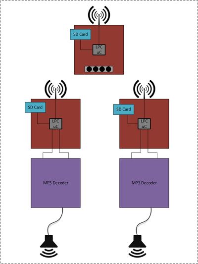
| Sound Buddy's core component is the SJOne board. For more information about the SJOne board click this link SJOne board or visit the main page of this Wiki.
Its system is composed of a sender device and one or more receiver devices. An MP3 file will be stored on the micro SD card which will be inserted into the sender's SD slot. The sender device will read and send out the raw MP3 data over the Nordic wireless protocol. Each device uses the built-in Nordic wireless transceiver which allows for one-way communication from the sender to the receiver(s). Plugged onto each on the other receivers is the MP3 decoder circuit. The receiver device will be waiting for the MP3 data. Once it detects data has been sent over, it begins to process the data by sending it out to the MP3 decoder. The MP3 decoder translates the raw data and sends it out to the onboard DAC. The DAC converts the raw data into audible signals that get pushed out to the audio0 jack where the speakers play the music. Now, that was a mouthful. Let's dive deeper into each of the component design. |
Sender Board
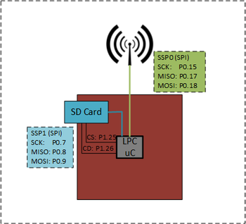
| The sender board uses the SD card and the Nordic wireless transceiver onboard. Using the SPI protocol, the SD card will be enabled for I/O purposes. There is a total of four wires utilized namely the SCK, MOSI, MISO, and CS. These wires are connected internally and the data transfer and chip select are handled by the driver and application code.
Similar to the SD card, the Nordic transceiver uses SPI protocol to send and receive data. This, too, is hooked up internally and the initialization and function are done through coding. The additional hardware part attached to the SJOne board is the 2.4GHz Duck Antenna RP-SMA to support the Nordic wireless data transfer. The Nordic data transfer can be sent on an on-air data rate of 250 kbps, 1Mbs, or 2Mbps depending on configuration. It has a maximum speed of 10Mbps on the SPI line and 3 separate 32 bytes TX and RX FIFO. On page 21 of the Nordic nrf24l01+ datasheet, the state diagram from communication can be found. Standby-II mode was used because it was determined to produce the fastest data transfer speed. If the TX FIFO detects a data packet uploaded, then the PLL starts and transmits immediately after PLL delay. To drive the Nordic device, the nrf24L01Plus class (included in the SJOne FreeRTOS project) was used to build a driver class. The driver simply checked if whether the TX FIFO is full and if it's not, data will be sent. It uses a polling method to achieve this. And, that is it for the sender device! Let's move on to the receiver device. |
Receiver Board
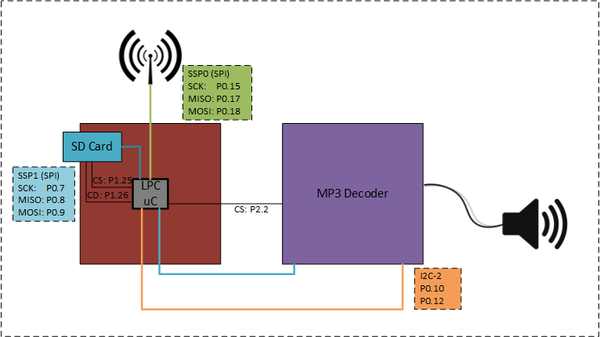
| The design of the receiver board is very similar to the sender board. Since its microcontroller is also the SJOne board, the onboard Nordic wireless transceiver and SD card slot were used for data transfer and storage. The raw data is sent over the Nordic wireless communication at about 200KBps even though it was able to send data at 1MBps. This is due to the write limitation that the available microSD cards imposed. The pins on the board for the SPI protocol are the same as those indicated in the sender board. A chip select pin was needed to enable the MP3 decoder. A GPIO pin from the SJOne board was configured for that purpose. The MP3 decoder board is connected on top of the SJOne board. The MP3 decoder shares the same SSP1 lines as the SD card. The software controls where the data transfer occurs. The MP3 decoder, also, utilizes the I2C protocol for initialization. The MP3 decoder circuit will be dissected later. Lastly, a speaker with an AUX port is attached to the MP3 decoder. |
MP3 Decoder
This circuit is based on the tutorial that details how to use the STA013 chip. The MP3 decoder circuit uses an STA013 MP3 decoder chip to translate raw MP3 data to audible data. A detailed data sheet can be found at STA013 MP3 Decoder. We used the standard configuration suggested by the manufacturer which recommends that all of the voltage sources higher than 3.3V be brought down to 3.3V to safely operate the device. Since the voltage supply from the SJOne board is 3.3V, this was not an issue.
For the data coming out of the MP3 decoder to produce music through speakers, the CS4334 DAC is used. This chip operates on a 5V supply so the SJOne board could not be used as a source. Instead, a 9V battery is used to supply the power. A 5V regulator circuit using a 7805 voltage regulator was built to step down the voltage level supply to prevent damage to the DAC device.
An audio jack is tied to the output of the DAC device to send music out to speakers with an auxiliary port. The speakers are powered internally with a rechargeable baterry. Any off-the-shelf speaker can be transformed into a Sound Buddy receiver.
Some assumptions are made about the usage of the STA013 device according to the tutorial. To summarize, for "normal" usage, its assumed that the STA013 will run off multimedia mode. The device will detect the MP3 data's bitrate and will send a signal that requesting for data. Data is fed to the STA013 up to 20Mbit/sec. The correct clock and data out to the DAC is also handled by the device. The STA013 will be driving the DAC and the output clock to synchronize with it. Since the tutorial uses a Cs4334 DAC chip in conjunction with a 14.7456 MHz crystal, those devices were used in the MP3 decoder as well. The DAC was chose due to it being inexpensive and its ability to output audio without noise.
The following is an illustration of the circuit described in the STA013 tutorial. Each significant portion of the circuit is boxed and labeled.
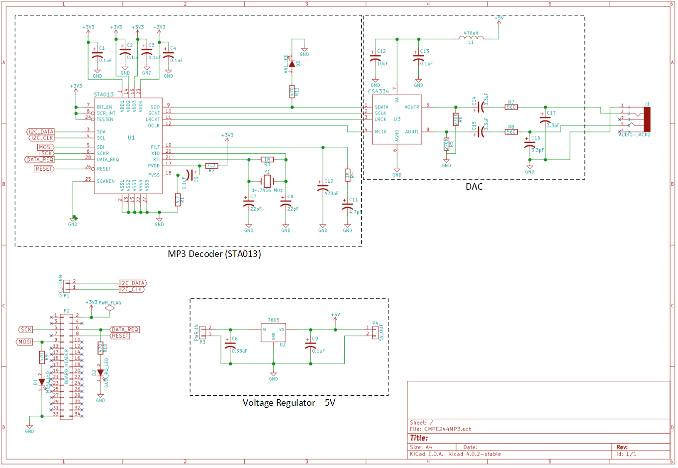
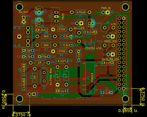
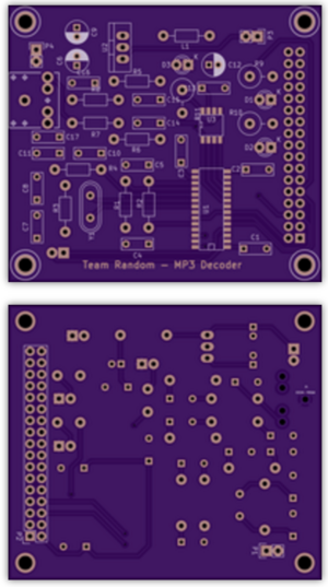
To package the MP3 decoder circuit nicely, a PCB was designed and printed to house the circuit. EAGLE PCB software was used to design the board layout. OSH Park was used to print the boards since the supply location was location locally in the Silicon Valley and the cost was affordable.
LEDs were added in pins for enable and data signals to assist with debugging to assure that the MP3 was functioning as designed.
| The illustration on the left is the layout the devices and interconnections on the board. It showcases both the top and bottom layers. The components were positioned with the thought of ease during the soldering of the devices and accessiblitity of the pins and ports.
|
Software Design
The software design is separated by three different components that make up the Sound Buddy system. These components are the sender, receiver, and MP3 decoder. Each required a driver to be implemented to get the subsystems functioning properly.
Sender Board
The sender board was designed to initialize the necessary device drivers (SPI/SSP & Nordic wireless) and run FreeRTOS. The tasks created were used to read data from the SD card to the RAM and from the RAM, send the data to the Nordic wireless device. There were two tasks created, one to read from the SD card and another to write to SPI bus out the Nordic wireless device.
Receiver Board
The receiver board also initializes the necessary device drivers (SPI/SSP & Nordic wireless) and run FreeRTOS. It also depends primarily on two tasks. One task to wait for the RX FIFO to receive a data packet and the send task to handle the writing to the SD card. As soon as the MP3 file is completely loaded into the SD card, it waits for a command to be sent to control the MP3 decoder functionality.
MP3 Decoder
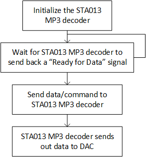
The tutorial describes the configuration and use of the STA013 MP3 decoder chip. The basic configuration and data transmit are depicted in the flowchart below.
With an I2C address of 0x86, communicating to the MP3 decoder chip was simple after configuration. The SJOne board's code base includes an I2C driver that helped drive the communication. When you start feeding in valid MP3 data, the chip detects the MP3 sample rate and creates the correct clock for the DAC and starts pushing data into it. The STA013 will ignore non-MP3 data so it is safe to send the entire file without needing to strip out ID3 tags, etc. The STA013 expects the most significant bit first, which corresponds to the SPI standard.
Hardware Implementation
Sender & Receiver Board
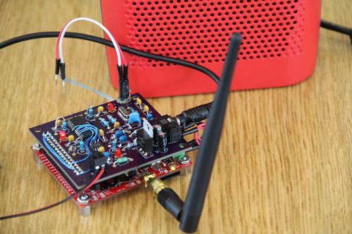
The following image is of the entire Sound Buddy system which includes the sender, receiver, and MP3 decoder board. The board in the middle is the sender board which is connected to the laptop to access the interface. The off-the-shelf speakers are connected to receiver boards.
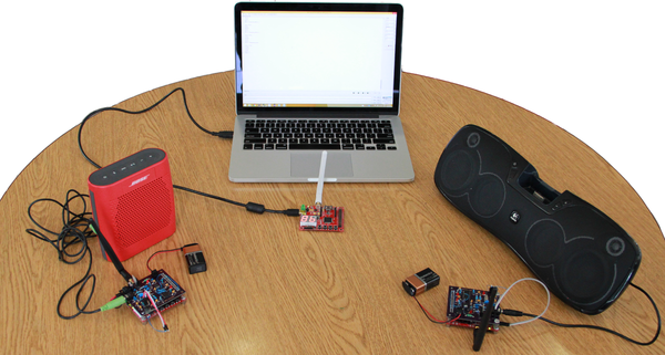
|
|
MP3 Decoder
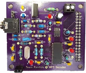
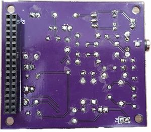
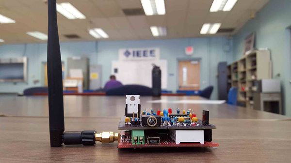
| When the PCB boards arrived, the components were carefully soldered on. The image on the left is the top of the of the board exposing the LEDs for debugging. The image on the right is the bottom of the board for reference. |
Software Implementation
This section will explain the software implementation a little deeper but not too deep. You can check out the code in the References link to view the interworkings of the code. A Nordic wireless driver and MP3 decoder driver were adopted and updated to fit the current project code base. Minimal changes were made to accommodate the project. For the Nordic wireless driver, the Nordic mesh class was thrown out of the window removing any data checks for integrity.
When the software was implemented, a variable was used to determine whether the code built was for the sender or the receiver.
#define NRF_SENDER 0          // 1 - Sender
                              // 0 - Receiver
To distinguish between control commands and the music data, a data packet structure was created. The available commands are play, pause, stop, and end.
The following is the psuedo code on how the packet is built:
void buildPacket(char * PACKET, header_cmd_t COMMAND, char * BUFFER, unsigned int DATASIZE){
	if DATASIZE > MAX_DATA_PACKET
		return;

	PACKET[0] = (COMMAND << 5);
	PACKET[0] |= DATASIZE;

	if(COMMAND == DATA)
	        memcpy(PACKET + PACKET_HEADER_SIZE, BUFFER, DATASIZE);
}
Sender Board
The sender board depends primarily on two tasks, ReaderTask and SenderWirelessTask, to function properly after initialization.
The job of the ReaderTask is to retrieve the data from the SD card so the SenderWirelessTask can send the data out to the Nordic wireless output buffer. Below, are the steps the to achieve this.
Nordic Wireless Transmission
   Step 1: Call the init function and set the device as a transmitter.
   Step 2: Check if TX FIFO is full. If it's full, then wait, else continue to the next step.
   Step 3: Send data packet to the TX FIFO. Data is sent out immediately from TX FIFO.
An if-statement controls whether to send commands or the MP3 data at the user interface console.
if option == '1'
       loop until end of DATA
	   READ_DATA_FROM_SD = (DATA);
           xQueueSend(g_sender_queue, DATA, portMAX_DELAY );
else if option == '2'
	buildPacket(PACKET, PLAY, NULL, 0);
	SenderWireless_service(PACKET);
else if option == '3'
	buildPacket(PACKET, PAUSE, NULL, 0);
	SenderWireless_service(PACKET);
else if option == '4'
	buildPacket(PACKET, STOP, NULL, 0);
	SenderWireless_service(PACKET);
Receiver Board
The receiver board requires the data packet to be parsed to pull the necessary information to process. Once the essential data is obtained, the data is sent through a queue to be saved into the SD card to be sent out to the MP3 decoder.
This code parses the packet to be processed in the recceiver tasks:
void decodePacket(char* packet, header_cmd_t* cmd, char** dataPtr, unsigned int* dataSize){
        *cmd = (header_cmd_t) ((packet[0] >> 5) & 0x07);
        *dataSize = (packet[0] & 0x1F);
        *dataPtr = packet + PACKET_HEADER_SIZE;
}
The following are the steps the Nordic driver cycles through relative to the receive task.
Nordic Wireless Receive
   Step 1: Call the init function and set the device as a receiver.
   Step 2: Check if data packet is available. If it's available, continue, else wait.
   Step 3: Clear packet available flag.
   Step 4: Read data packet from RX FIFO.
To handle the commands/data the following pseudo code is added to the receiver task:
if cmd == DATA
	STORE_DATA(DATA)
else if cmd == PLAY
	vTaskResume(mp3Task->getTaskHandle());
else if cmd == PAUSE
	vTaskSuspend(mp3Task->getTaskHandle());
else if cmd == STOP
	mp3Task->stop();
	vTaskSuspend(mp3Task->getTaskHandle());
MP3 Decoder
Once the STA013 MP3 decoder chip is initialized, sending data to the device becomes a breeze.
A long list of configuration settings must be uploaded correctly to STA013. The following is the initialization code after uploading the settings is completed. The important configuration to note below is how the clocks are handled. Proper configuration of these rates are necessary to have STA013 functioning correctly.
void sta013StartDecoder(void)
{
	// Soft reset
	sta013WriteReg(STA_REG_SOFT_RESET,		0x01);
	sta013WriteReg(STA_REG_SOFT_RESET,		0x00);

	// Mute
	sta013WriteReg(STA_REG_MUTE,			0x01);

	// Configure DAC output for PCM1774 DAC:
	sta013WriteReg(STA_REG_PCMDIVIDER,		0x03); // changed to 256xFs 16-bit (used to be 0x01)
	sta013WriteReg(STA_REG_PCMCONF,			0x30); // changed to LRCKT I2S 16-bit mode (used to be 0x21)

	// Configure PLL for MP3 rates
	sta013WriteReg(STA_REG_PLLFRAC_441_H,		0x04);
	sta013WriteReg(STA_REG_PLLFRAC_441_L,		0x00);
	sta013WriteReg(STA_REG_PLLFRAC_H,		0x55);
	sta013WriteReg(STA_REG_PLLFRAC_L,		0x55);
	sta013WriteReg(STA_REG_MFSDF_441,		0x10);
	sta013WriteReg(STA_REG_MFSDF,			0x0F);

	// Configure interface polarities, etc
	sta013WriteReg(STA_REG_RESERVED,      		0x03);
	sta013WriteReg(STA_REG_PLLCTL_2,		0x0C);
	sta013WriteReg(STA_REG_PLLCTL_3,		0x00);
	sta013WriteReg(STA_REG_PLLCTL_1,		0xA1);
	sta013WriteReg(STA_REG_SCLK_POL,		0x00);
	sta013WriteReg(STA_REG_REQ_POL,			0x01);
	sta013WriteReg(STA_REG_DATA_REQ_ENABLE,		0x04);
}
The following is code that locks the SPI bus to send data out to the MP3 decoder. The lock is needed to prevent bus contention between the Nordic device and MP3 decoder
while(streamedBytes < bytesRead) {
     if(STA013_NEEDS_DATA()){
	spi1_lock;
	SELECT_MP3_CS();
	ssp1_exchange_byte(data[streamedBytes++]);
	DESELECT_MP3_CS();
	spi1_unlock();
}
Testing & Technical Challenges
During the development of Sound Buddy, many problems came about. Some problems were resolved and others forced us to rethink the design. There was a lot of learning happening during the resolution of the problems.
This section aims to help you resolve design issues and give you hints on how to fix issues that we ran into.
Issue #1: Repurposing the existing Nordic driver code
In the SJOne project, a Nordic driver was already created. This was used for the implementation of a mesh network. Now, we were warned that this would lead to a lot of overhead and slowdown our code. We decided to make the driver lean and build it for the functions that we need. In doing so, things started to get complicated. Namely, the interrupt that was used in the existing driver was slowing our code down but at one point it was causing unexpected crashes.
Solution #1: Be simple, efficient
We decided to try out a more simple way. There were functions in a lower level driver that allowed us to look at FIFO buffers. We went straight to the source instead of trying to get fancy. Even though using interrupts may have been considered best practice, for the purpose of having a functioning product at the end of the project deadline to demo, we simplified the sending and receiving of the data.
Issue #2: Buffer data transfer speed
This was a foreseen issue at the beginning of the project. How were we going to handle the buffer issue? Well, the buffer issue was only a problem when we were testing speeds. We didn't need the data to be sent very fast because we were limited buy the write speed of the SD card. We still wanted to see how fast we can get the speed to transfer.
Solution #2: Increase the data and buffer
We didn't have time to implement a fully functional stream due to time constraints so we downloaded the file to the SD card on the receiver board instead. Essentially, the SD card was our buffer. We tested various solutions for a faster speed. These test results can be found in the Testing section below.
Issue #3: MP3 decoder circuit initialization
During the prototype of the MP3 decoder circuit, initializing the STA013 IC was the most difficult task. The chip required what looked like hundreds of registers to be initialized. This was too many to take into account for given the time crunch that we were in but we attempted to initialize anyway. We hit a brick wall and couldn't figure out why we get Ready signal but couldn't output any audible data.
Solution #3: Don't reinvent the wheel
We resorted to using code that was dug up from another team's project. Using the STA013 driver in that project helped us initialize the STA013 chip properly.
Issue #4: MP3 decoder's unexpected behavior
We got the MP3 decoder to initialize but it still wasn't functioning properly. We noticed a design flaw. Earlier, we had decided to hardwire the chip select on the STA013 IC thinking that it will always be enabled. This was giving us problems.
Solution #4: Exercise good practice with wiring HW
The chip was working as expected as soon as we decided not to hardwire the chip enable on the board and instead use the STA013 driver's chip enable function to control it.
Issue #5: ICs were not what we expected
As we designed our PCB, we were still ordering our parts. Being novices with PCB design, we didn't double check the IC packaging. Wehen we recieved the PCB, we realized that the IC package for STA013 was bigger than we expected.
Solution #5: Make do with what you have
In order to solve this, we could have reordered the PCB boards but that would take too long and cost too much. Instead, we decided to bend the legs in an utilize the teams soldering skills. We can be surgeons with these skill. JK.
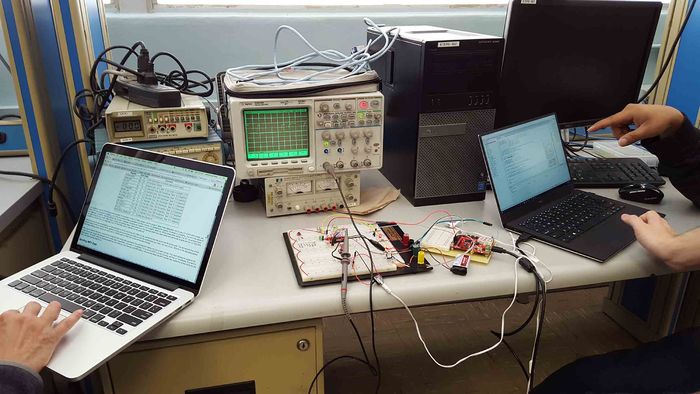
The prototype board for the MP3 decoder circuit
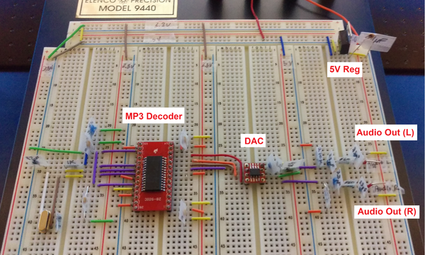
Before soldering the components on the PCB, we tested on a prototype board to make sure the design was functioning correctly. We found some connection issues and resolved it appropriately on the PCB when the components were soldered.
Testing
Nordic Test Cases
- Sending a byte over nordic to all of the receiver devices
- Sending text file over nordic to all of the receiver devices
- Sending an MP3 file over nordic to a receiver device
- Sending an MP3 file over nordic to all of the receiver devices
- Performance test to increase data transfer speed of Nordic
- The FATfs information site was referenced to run similar testbench and understand how to increase data transfer rates.
- The following is a list of test cases executed for performance testing:
  	Format:
        data, sizeof(data), wait, fileSize, priority

	2 item, 1024 size, semaphore + delay(1), audio1 ~ 2mb
	time   bytes  kbps
	90144 2885632 256

	2 item, 1024 size, poll, audio1 ~ 2mb
	time   bytes  kbps
	26948 2885632 856

	10 item, 1024 size, poll, audio1 ~ 2mb
	time   bytes  kbps
	26947 2885632 856

	10 item, 1024 size, poll, audio1 ~ 2mb, reader > sender
	time   bytes  kbps
	26917 2885632 857

	2 item, 2048 size, poll, audio1 ~ 2mb, reader > sender
	time   bytes  kbps
	24978 2885632 924

	2 item, 4092 size, poll, audio1 ~ 2mb, reader > sender
	time   bytes  kbps
	22887 2883584 1007

	2 item, 4092 size, poll, audio1 ~ 2mb, reader = sender
	time   bytes  kbps
	21918 2883584 1052

	4 item, 4092 size, poll, audio1 ~ 2mb, reader = sender
	time   bytes  bps
	21980 2883584 1049

	1 item, 4092 size, poll, audio1 ~ 2mb, reader
	time   bytes  kbps
	1 	4096  32768
MP3 Decoder Tests Cases
- Send a sample MP3 file from receiver's SD card
- Send an full MP3 file from receiver's SD card
Integration Test Cases
- Send and play an MP3 file to one reciever board
- Broadcast to and play an MP3 file on all receiver boards
All the test cases were executed. A handful failed at first execution but those that failed were resolved. The tests were run again until we agreed the function was behaving as expected and no major/minor defects were observed. At the end of the project cycle, all of the test cases listed above were run successfully.
Conclusion
Sound Buddy is only at its first stages of development. At the end of this project cycle, we have Sound Buddy demoing its ability to send data over Nordic and play music on one or multiple receiver devices.
In relation to the FreeRTOS, we were able to exploit the function of queues to communicate between tasks. Our knowledge about the drivers in the SJOne project was also strengthened because we had to understand the drivers to utilize them with the peripherals. There was a lot of research that went into this project. The skill of reading datasheets was exercised extensively. This project was a practical use of the topics learnt from the Embedded Systems course at SJSU.
We were able to gain insight on how to work as a team to get things done. Even though we would have hoped to accomplish more with Sound Buddy such as a visually pleasing GUI, an actual stream of data from one board to the other, and professional product packaging, time became our biggest constraint. Working with such a diverse group of team members, we were able to learn from each other and adopt each others' skills at some points during the project.
This project was a stressful yet enjoyable one to take part of.
Project Video
Project Source Code
Sound Buddy's Guts (source code)

References
Acknowledgement
Preet Kang, who taught us what we needed to know to use the SJOne board and FreeRTOS for our project.
...And humor. For without it, we would not be able to enjoy each other's presence during the completion of this project.
References
- Wiki Page Development

