Difference between revisions of "F12: Self-Driving GPS Following Car"
(→Schedule) |
|||
| Line 29: | Line 29: | ||
== Schedule == | == Schedule == | ||
<table class="wikitable"> | <table class="wikitable"> | ||
| − | <th>Week Number</th> <th> | + | <th>Week Number</th> <th>Planned Items</th> <th>Actual Items</th> |
<tr> | <tr> | ||
| Line 43: | Line 43: | ||
</td> | </td> | ||
<td> | <td> | ||
| − | * | + | * Ordered parts |
| − | * | + | * Designed proximity sensor placement |
| + | * Designed obstacle avoidance algorithm | ||
| + | * Designed move to destination GPS algorithm | ||
</td> | </td> | ||
| Line 57: | Line 59: | ||
* Upgrade leading car with microcontroller, XBee, GPS, <BR/> and a battery pack | * Upgrade leading car with microcontroller, XBee, GPS, <BR/> and a battery pack | ||
* Upgrade following car with microcontroller, XBee, GPS, <BR/> compass, proximity sensors, motor controllers, and a <BR/> battery pack | * Upgrade following car with microcontroller, XBee, GPS, <BR/> compass, proximity sensors, motor controllers, and a <BR/> battery pack | ||
| − | * Read GPS | + | * Read GPS coordinate from GPS module |
</td> | </td> | ||
<td> | <td> | ||
| − | * | + | * Tested proximity sensors |
| − | * | + | * Finished ADC and PWM drivers |
| − | * GPS | + | * Paired XBee modules |
| + | * Read GPS coordinates and computed required bearing and <BR/>distance to travel to destination | ||
</td> | </td> | ||
</tr> | </tr> | ||
| Line 72: | Line 75: | ||
</center> </td> | </center> </td> | ||
<td> | <td> | ||
| − | |||
* Read direction from compass | * Read direction from compass | ||
* Enable car driving capabilities / motor controllers | * Enable car driving capabilities / motor controllers | ||
| Line 78: | Line 80: | ||
</td> | </td> | ||
<td> | <td> | ||
| − | * | + | * Motors controllers fully interfaced |
| − | * | + | * Mounted proximity sensors, motor controllers, microcontroller, and GPS |
| − | + | * Created upgrade module for leading car | |
| − | * | ||
</td> | </td> | ||
</tr> | </tr> | ||
| Line 94: | Line 95: | ||
</td> | </td> | ||
<td> | <td> | ||
| − | * | + | * Tested obstacle avoidance |
| + | * Sent GPS data from leading car to following car | ||
| + | * Swapped to non-tilt compensated compass | ||
| + | * Mounted compass | ||
| + | * Restructure and reorganize code | ||
</td> | </td> | ||
</tr> | </tr> | ||
| Line 107: | Line 112: | ||
</td> | </td> | ||
<td> | <td> | ||
| − | * | + | * Tested obstacle avoidance |
| + | * Swapped a proximity sensor to unify sensors | ||
| + | * Swapped to less power hungry motor controllers | ||
| + | * New motor controllers fully interfaced | ||
| + | * Upgraded to use 5xAA battery pack | ||
| + | * Rewired parts with finalized placement | ||
</td> | </td> | ||
</tr> | </tr> | ||
| Line 120: | Line 130: | ||
</td> | </td> | ||
<td> | <td> | ||
| − | * | + | * Tested obstacle avoidance |
| + | * Tested move to GPS coordinate | ||
</td> | </td> | ||
</tr> | </tr> | ||
| Line 134: | Line 145: | ||
</td> | </td> | ||
<td> | <td> | ||
| − | * | + | * Tested move to GPS coordinate |
</td> | </td> | ||
</tr> | </tr> | ||
Revision as of 19:38, 17 December 2012
Contents
Self-Driving GPS Following Car
Abstract
The objective of this project is to create an autonomous vehicle that follows another car. A leading car will continually inform the autonomous car of its location. The autonomous car will then drive to the target location while avoiding obstacles along the way.
Introduction and Objectives
The Self-Driving GPS Following Car follows another car by driving to the GPS coordinates of the leading car. A ZigBee communication link transmits the GPS data from the leading car to the following car. The following car utilizes a GPS and a compass to determine its own location and orientation relative to magnetic north. Using the two pairs of GPS coordinates and the orientation of the car, the bearing and distance necessary to be traveled is calculated. The car uses proximity sensors, so the car can avoid obstacles while navigating to the destination.
The project required the following objectives to be accomplished:
- Read GPS coordinates of the leading car and the following self-driving car
- Use XBee modules to send and receive GPS coordinates from the leading car to the following car
- Compute the true north bearing and distance necessary for the following car to reach the leading car
- Account for difference between true north and magnetic north in bearing calculation
- Read the magnetic north bearing using a compass
- Read the distance to objects using proximity sensors
- Control steering motor to steer left, right, and straight using a motor controller
- Control direction motor to move forward, backward, and stop using a motor controller
- Determine algorithm to drive toward destination
- Determine algorithm to avoid obstacles
Team Members and Responsibilities
- Elias Barboza
- PWM driver, motor controllers, and obstacle avoidance
- Caleb Chow
- Read compass, read GPS coordinates, and move toward target GPS coordinates
- Stephen Lu
- ADC driver, read proximity sensors, compute distance based on measurement, and obstacle avoidance
Schedule
| Week Number | Planned Items | Actual Items |
|---|---|---|
| Week 1: Design
|
|
|
| Week 2: Construction
|
|
|
| Week 3: Drivers
|
|
|
| Week 4: Coding
|
|
|
| Week 5: Coding
|
|
|
| Week 6: Testing
|
|
|
| Week 7: Finalization
|
|
|
Parts List & Cost
Give a simple list of the cost of your project broken down by components. Do not write long stories here.
| Parts | Quantity | Cost | Link |
|---|---|---|---|
| RC Car -
| 2 | $25 | Previously owned
|
| GPS -
| 2 | $37.21 | |
| XBee Module -
| 2 | $24.95 | |
| Motor Controller -
| 2 | $17.99 | |
| Compass -
| 1 | $14.95 | |
| Sonar Range Finder -
| 2 | $26.95 | |
| Ultrasonic Range Finder -
| 1 | ~$50 | |
| Microcontroller -
| 1 | ~$120 | |
Design & Implementation
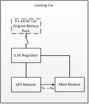
Hardware Design The leading car consists of the following additional hardware:
- XBee module
- GPS module
- 3.3V regulator circuit
The leading car is responsible for sending its GPS coordinates to the following car. This is accomplished by sending the raw GPS data over ZigBee to the following car. The GPS and XBee modules both use UART to communicate, so no microcontroller is necessary. The paired XBee modules will take care of the data transfer. Both modules ran off the same 3.3V power supply, which came from a regulator off of the car’s battery pack.
File:CmpE146 F12 T7 Leading Car Block Diagram.png
Hardware Design
Discuss your hardware design here. Show detailed schematics, and the interface here.
Hardware Interface
In this section, you can describe how your hardware communicates, such as which BUSes used. You can discuss your driver implementation here, such that the Software Design section is isolated to talk about high level workings rather than inner working of your project.
Leading Car

Leading Car Block Diagram
- GPS – UART
- Outputs GPS data on Tx to XBee Rx
- XBee – UART
- Inputs data to send on Rx from GPS Tx
- Power Supply – 3.3V
- Supply power to GPS and XBee modules
- Add 3.3V voltage regulator with filtering capacitors to RC car’s battery pack
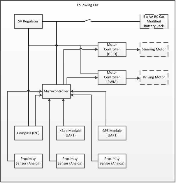
Following Car

Following Car Block Diagram
- Microcontroller
- 2012 SJSU One Board (LPC1758)
- GPS – UART
- P2.8 = Tx, P2.9 = Rx
- PINSEL4 = 0b10 for both
- Xbee – UART3
- P4.28 = Tx, P4.29 = Rx
- PINSEL9 = 0b11 for both
- I2C2 Devices
- P0.10 = SDA, P0.11 = SCL
- PINSEL0 = 0b10 for both
- Components :
- Proximity sensor (SRF08)
- Compass
- P0.10 = SDA, P0.11 = SCL
- Proximity Sensors (LV-MaxSonar-EZ4) – ADC4 and ADC5
- P1.30 = AD0.4
- P1.31 = AD0.5
- PINSEL3 = 11 for both
- Motor Controllers (2) – PWM
- P1.20 = PWM1.2
- P1.24 = PWM1.5
- PINSEL3 = 10 for both
- Power Supply – 5.0V from RC car's original battery pack
- Supply power to motor controllers for motors
- Supply power to SRF08 proximity sensor
- Power Supply – 3.3V
- Microcontroller 3.3V output
- Supply power to GPS, Xbee, and LV-MaxSonar-EZ4 proximity sensors
Software Design
Show your software design. For example, if you are designing an MP3 Player, show the tasks that you are using, and what they are doing at a high level. Do not show the details of the code. For example, do not show exact code, but you may show psuedocode and fragments of code. Keep in mind that you are showing DESIGN of your software, not the inner workings of it.
Implementation
This section includes implementation, but again, not the details, just the high level. For example, you can list the steps it takes to communicate over a sensor, or the steps needed to write a page of memory onto SPI Flash. You can include sub-sections for each of your component implementation.
Testing & Technical Challenges
Describe the challenges of your project. What advise would you give yourself or someone else if your project can be started from scratch again? Make a smooth transition to testing section and described what it took to test your project.
Include sub-sections that list out a problem and solution, such as:
Wifi Connection Issues
Many wifi connection issues were encountered. To solve this problem, a dedicated task was created to re-connect to wifi if the connection was ever lost.
Conclusion
Conclude your project here. You can recap your testing and problems. You should address the "so what" part here to indicate what you ultimately learnt from this project. How has this project increased your knowledge?
Project Video
Upload a video of your project and post the link here.
Project Source Code
Send me your zipped source code and I will upload this to SourceForge and link it for you.
References
Acknowledgement
Any acknowledgement that you may wish to provide can be included here.
References Used
List any references used in project.
Appendix
You can list the references you used.