Difference between revisions of "F15: Fury"
Proj user11 (talk | contribs) (→Ultrasonic Sensor) |
(→Acknowledgement) |
||
| (240 intermediate revisions by 2 users not shown) | |||
| Line 3: | Line 3: | ||
== Abstract == | == Abstract == | ||
| − | This | + | |
| + | This project implements a self-driving car with the ability to have programmable routes and do obstacle avoidance. Programmable routes are implemented through an Android application, while precise motion to a programmed destination is implemented by using an electronic compass and GPS. Also, the self-driving car provides an RPM speed controlled motor for constant speed in different terrains as well as a master controller with obstacle avoidance algorithms and steering control to direct the car to its final destination. | ||
== Schedule == | == Schedule == | ||
| Line 142: | Line 143: | ||
| $12.99 | | $12.99 | ||
| http://twinind.com/index.php/products/prototyping-boards | | http://twinind.com/index.php/products/prototyping-boards | ||
| + | |- | ||
| + | ! scope="row"| 15 | ||
| + | | Magnet | ||
| + | | $0.99 x 5 | ||
| + | | - | ||
| + | |- | ||
| + | ! scope="row"| 16 | ||
| + | | LCD display | ||
| + | | - | ||
| + | | Given by preet | ||
| + | |- | ||
| + | ! scope="row"| 17 | ||
| + | | 7-segment display | ||
| + | | - | ||
| + | | Given by preet | ||
|- | |- | ||
|} | |} | ||
| Line 147: | Line 163: | ||
== Introduction == | == Introduction == | ||
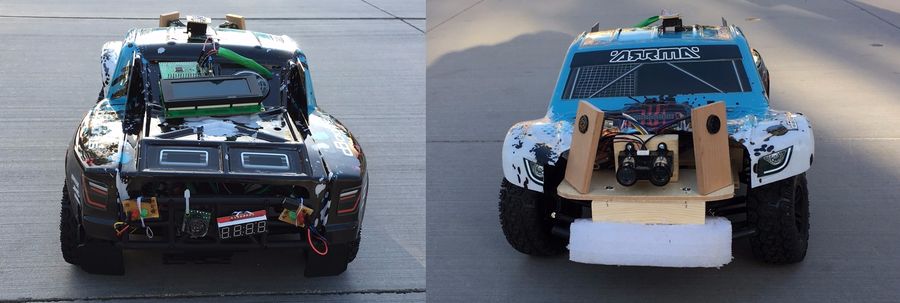
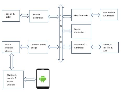
| − | ==== The | + | This project is aimed at developing a RC car with a self-drive capability based on controller interaction over the CAN (Controller Area Network) bus. This car can steer itself through co-ordinates fed by Google maps and correct its course when it sees an obstacle. To achieve this objective, we plan to integrate 5 controllers dedicated to specific roles that can pass messages over a common CAN communication bus. In addition, the prototype would involve an Android mobile application for data monitoring and controlling, to keep a track of the car remotely and feed it the required checkpoints to reach its destination. Through the android app, user can feed in the desired destination through google maps interface. The car would follow based on co-ordinates and heading provided by its GPS and compass respectively. |
| − | * [[#Master Controller|''Master Controller'']] | + | |
| − | * [[#Motor and I/O controller|''Motor and I/O controller'']] | + | [[File:F15_Fury.jpg|center|900px]] |
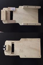
| − | * [[#Sensor Controller|''Sensor Controller'']] | + | [[File:F15_Fury_hardware_board_design.jpg|thumb|left|150px|Hardware Frame]] |
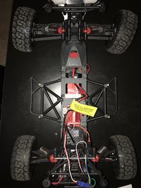
| − | * [[#Geographical Controller and Compass|''Geographical Controller and Compass'']] | + | [[File:F15_Fury_chassis.jpg|thumb|right|200px|Car chasis]] |
| − | * [[#Android & Communication Bridge Controller|''Android & Communication Bridge Controller'']] | + | |
| + | == Overview == | ||
| + | * The GPS would wait for a satellite fix, upon getting a fix, the controller would relay the information over the CAN bus to Android device through its controller. | ||
| + | * Through the android app co-ordinates of destination has to be selected by dropping a marker on the map. | ||
| + | * The android app would calculate all the intermediate checkpoints wherever there are turns. | ||
| + | * These checkpoints are sent over to the geo controller module. | ||
| + | * Upon send a command issued by android app, the master would send a command to the motor control to move forward. | ||
| + | * Any obstacle detected by the ultrasonic sensors would override the current path and try to avoid the obstacle. | ||
| + | * The master controller would compute the course correction and reconfigure the required controllers once the car has passed the obstacle. | ||
| + | * The IO controller is responsible for monitoring the data on the CAN bus and displaying the information on the mounted LCD panel. | ||
| + | * Stop trigger can be given to the car remotely. | ||
| + | * Once the car reaches the first checkpoint, it will update to the next checkpoint automatically. In this way, the process continues till the car reaches the destination. | ||
| + | |||
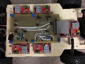
| + | [[File:F15_Fury_board_design.jpg|thumb|right|300px]] | ||
| + | |||
| + | [[File:F15_Fury_block_diagram.jpg|center|thumb|Block Diagram|1500px]] | ||
| + | |||
| + | == The Controllers == | ||
| + | * [[#Master Controller|'''Master Controller''']] | ||
| + | ** '''''[https://www.linkedin.com/in/bhargavasg Bhargava Sreekantappa Gayathri] ''''' | ||
| + | ** ''''' Thiruparan Balachandran ''''' | ||
| + | * [[#Motor and I/O controller|'''Motor and I/O controller''']] | ||
| + | ** ''''' Sin Yu Ho ''''' | ||
| + | ** ''''' Nimmi Bhatt ''''' | ||
| + | * [[#Sensor Controller|'''Sensor Controller''']] | ||
| + | ** ''''' Christopher Laurence ''''' | ||
| + | ** ''''' Julio Fuentes ''''' | ||
| + | * [[#Geographical Controller and Compass|'''Geographical Controller and Compass''']] | ||
| + | ** '''''[https://www.linkedin.com/in/abhishekgurudutt Abhishek Gurudutt] ''''' | ||
| + | ** '''''[https://www.linkedin.com/in/tejeshwarchandrakamaal Tejeshwar Chandra Kamaal] ''''' | ||
| + | * [[#Android & Communication Bridge Controller|'''Android & Communication Bridge Controller''']] | ||
| + | ** ''''' [https://www.linkedin.com/in/chinmayidivakara Chinmayi Divakara] ''''' | ||
| + | ** ''''' [https://www.linkedin.com/in/praveenprabhakaran03 Praveen Prabhakaran] ''''' | ||
== Design & Implementation == | == Design & Implementation == | ||
| − | The | + | |
| + | === CAN Interface === | ||
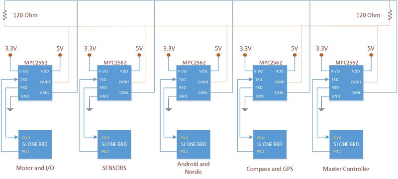
| + | The CAN interface was implemented by using the MPC2562 transceiver. The MPC2562 transceiver supports data rates up to 1Mbps and also provides a separate I/O supply pin to support 1.8-5V signaling on the controller side. Below is a diagram of the CAN interface implemented on Fury. | ||
| + | |||
| + | |||
| + | [[File:F15 243 Fury can interface.jpg | 800px]] | ||
| + | [[File:F15_Fury_CAN_analyzer_tool.png |thumb|right|300px|CAN analyzer tool]] | ||
| + | |||
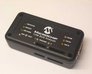
| + | '''[http://www.microchip.com/Developmenttools/ProductDetails.aspx?PartNO=APGDT002 Can bus analyzer]''' | ||
| + | |||
| + | A very useful tool for debugging CAN bus. The CAN BUS Analyzer Tool is intended to be a simple-to-use, low-cost CAN Bus monitor which can be used to develop and debug a high-speed CAN network. The CAN Analyzer tool supports CAN 2.0b and ISO 11898-2 (high-speed CAN with transmission rates of up to 1 Mbit/s). The tool can be connected to the CAN network using the USB connector. | ||
=== CAN 11-bit ID Format === | === CAN 11-bit ID Format === | ||
| Line 196: | Line 254: | ||
==== Group Members ==== | ==== Group Members ==== | ||
| − | *''''' Bhargava Sreekantappa Gayathri ''''' | + | *'''''[https://www.linkedin.com/in/bhargavasg Bhargava Sreekantappa Gayathri] ''''' |
*''''' Thiruparan Balachandran ''''' | *''''' Thiruparan Balachandran ''''' | ||
| Line 230: | Line 288: | ||
| 10/18/2015 | | 10/18/2015 | ||
| Come up with a kill switch mechanism with the existing remote control and complete building the car. | | Come up with a kill switch mechanism with the existing remote control and complete building the car. | ||
| − | | | + | | Completed |
| − | | | + | | 12/04/2015 |
| − | | | + | | Delayed to focus on primary objectives for project |
|- | |- | ||
! scope="row"| 6 | ! scope="row"| 6 | ||
| Line 238: | Line 296: | ||
| 10/30/2015 | | 10/30/2015 | ||
| Set up inter board communication with CAN and test specific messages sent to a module and broadcast messages. | | Set up inter board communication with CAN and test specific messages sent to a module and broadcast messages. | ||
| − | | | + | | Completed |
| − | | | + | | 10/30/2015 |
| | | | ||
|- | |- | ||
| Line 246: | Line 304: | ||
| 10/30/2015 | | 10/30/2015 | ||
| Get the car running by integrating with the motor controller and Implement logging. | | Get the car running by integrating with the motor controller and Implement logging. | ||
| − | | | + | | Completed |
| − | | | + | | 10/30/2015 |
| | | | ||
|- | |- | ||
| Line 254: | Line 312: | ||
| 11/13/2015 | | 11/13/2015 | ||
| Integrate GPS module and implement the algorithm for the car to travel to the destination with a hard coded Destination co-ordinates. | | Integrate GPS module and implement the algorithm for the car to travel to the destination with a hard coded Destination co-ordinates. | ||
| − | | | + | | Completed |
| − | | | + | | 11/13/2015 |
| | | | ||
|- | |- | ||
| Line 262: | Line 320: | ||
| 11/21/2015 | | 11/21/2015 | ||
| Integrate sensor module and implement obstruction avoidance mechanism. | | Integrate sensor module and implement obstruction avoidance mechanism. | ||
| − | | | + | | Completed |
| − | | | + | | 10/30/2015 |
| | | | ||
|- | |- | ||
| Line 270: | Line 328: | ||
| 11/25/2015 | | 11/25/2015 | ||
| Integrate the Bluetooth bridge and get co ordinates from hone as well as send vehicle parameters to the phone for displaying in the app. | | Integrate the Bluetooth bridge and get co ordinates from hone as well as send vehicle parameters to the phone for displaying in the app. | ||
| − | | | + | | Completed |
| − | | | + | | 11/25/201 |
| | | | ||
|- | |- | ||
| Line 278: | Line 336: | ||
| 12/15/2015 | | 12/15/2015 | ||
| Testing and fine tuning as required. | | Testing and fine tuning as required. | ||
| − | | | + | | Completed |
| − | | | + | | 12/15/2015 |
| | | | ||
|} | |} | ||
| Line 298: | Line 356: | ||
The main battery which will power the motors will be having the kill switch in its path, when ever the kill switch is armed main battery will not be fed to the motors. | The main battery which will power the motors will be having the kill switch in its path, when ever the kill switch is armed main battery will not be fed to the motors. | ||
| − | === | + | ==== Software Design ==== |
| − | + | * The Master Controller is responsible for any action the car performs. | |
| − | + | * To control the actions of the car, the Master Controller relies upon the periodic scheduler of the FreeRTOS. | |
| − | + | * The periodic scheduler ensures that the Sensor, geo-controller messages are read periodically and the actuation command is sent out to the motor controller. | |
| + | * To read and send messages to the other controllers, the Master Controller makes use of the CAN bus. The controll signal to the motor controller is sent out every 100ms. | ||
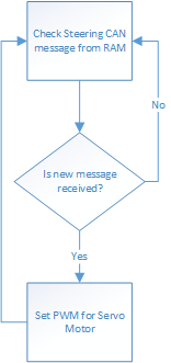
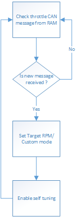
| + | * Since the master controller receives a huge number of messages, the Full CAN feature of LPC 1758 is made used. Enabling Full CAN will ensure that the Master Controller will not check for the CAN messages periodically but will directly read a memory location in the RAM which will havr the CAN message. | ||
| + | * For debuggin puposes, the Telemetry module provided by Preet is used. The Telemetry module logs the pre-decided variables in memory and the values of those variables can be read out via the telemetry viewer. This method is better than the printing the values or logging those values in a file as it is realtime and runs in the background. | ||
| + | * Additionally, there are 4 LEDs at the back of the car. The 2 red LEDs light up when ever the car is braking or is stopped. The 2 green LEDs on the either sides of the car blinks when the car is taking a turn. If the car is taking a left turn then the left green LED will blink and vice versa. | ||
| + | * Apart from the LED indications. The Master controller also sends useful debug information to the IO controller to be displayed on the App. | ||
=== Controller Communication Table === | === Controller Communication Table === | ||
| Line 354: | Line 417: | ||
| STEERING | | STEERING | ||
| | | | ||
| − | + | Msg : 2 bits :Direction data | |
|- | |- | ||
! scope="col"| 7 | ! scope="col"| 7 | ||
| − | | | + | | 0x022 |
| − | | | + | | Motor Controller |
| − | | | + | | THROTTLE |
| | | | ||
| − | + | Msg : 1 bit : Increment speed | |
| − | + | Msg : 2 bits : Custom speed number | |
| − | + | Msg : 1 bit : Use custom | |
| − | + | Msg : 1 bit : Forward | |
| − | + | Msg : 1 bit : stop | |
| − | |||
| − | |||
| − | |||
|- | |- | ||
| + | |||
|} | |} | ||
| − | |||
=== Implementation === | === Implementation === | ||
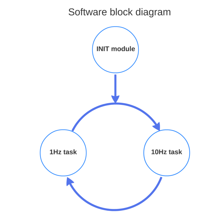
| − | + | The block diagram of the software imlplementation is as follows: | |
| + | [[File:F15_Fury_Master_software_flow.png| 700px | center| thumb | Master Controller software flow]] | ||
| + | |||
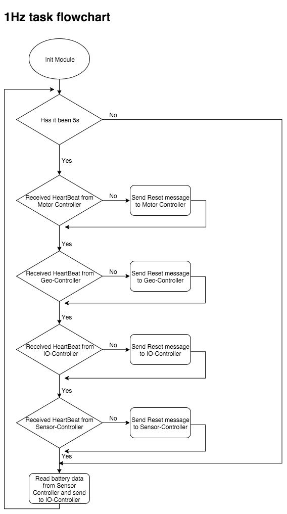
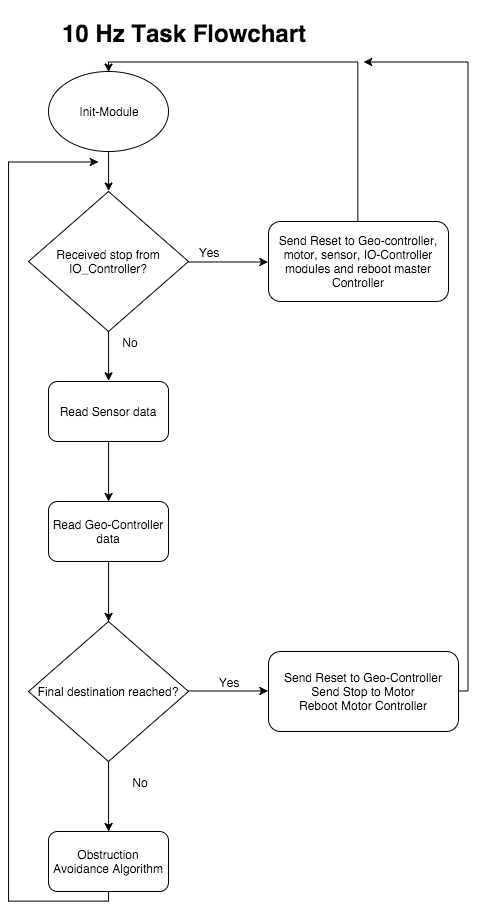
| + | Most of the processing in the master controller took place in the 10Hz task. Some non-critical processing happened at 1Hz and the initialization took place in the period_init task. Below are the detailed screen shot of the different tasks: | ||
| + | |||
| + | [[File:F15_Fury_master_Init-process.png| 700px | left| thumb | Master Controller init task]] | ||
| + | |||
| + | [[File:F15_Fury_master_1hz_task.png| 700px | center| thumb | Master Controller 1Hz task]] | ||
| + | |||
| + | |||
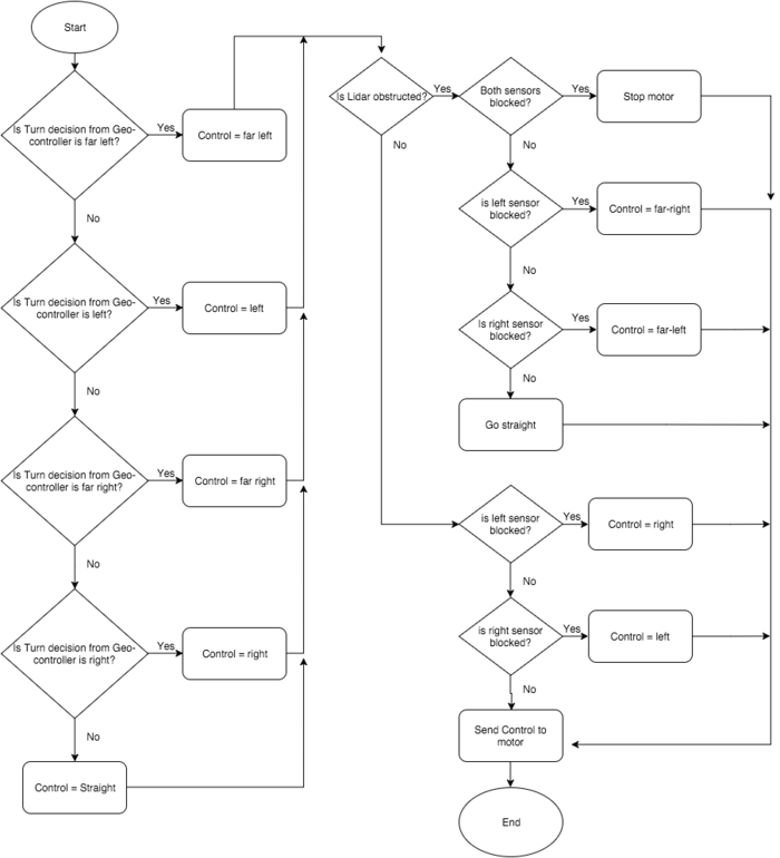
| + | The obstruction avoidance algorithm took the messages from the Geo-controller and the sensor controller and turns the car suitably guiding it towards the checkpoint. Below is the detailed flowchart for the same: | ||
| + | |||
| + | [[File:F15_Fury_master_obstruction_algo.png| 700px | left| thumb | Master Controller obstruction avoidance algorithm]] | ||
| + | [[File:F15_Fury_master_10hz_task.png| 700px | center| thumb | Master Controller 10Hz task]] | ||
| + | |||
| + | Since Full CAN was implemented, the master controller was never required to use any queues or wait for the CAN message to be received. | ||
=== Testing & Technical Challenges === | === Testing & Technical Challenges === | ||
| − | + | * Make sure the CAN message IDs for FullCAN is added in the ascending order and this includes the dummy IDs as well. | |
| − | Make | + | * Make sure to read the CAN header file thoroughly before implementing FullCAN. |
== Motor and I/O controller == | == Motor and I/O controller == | ||
| Line 457: | Line 532: | ||
=== Hardware Design === | === Hardware Design === | ||
| − | |||
| − | |||
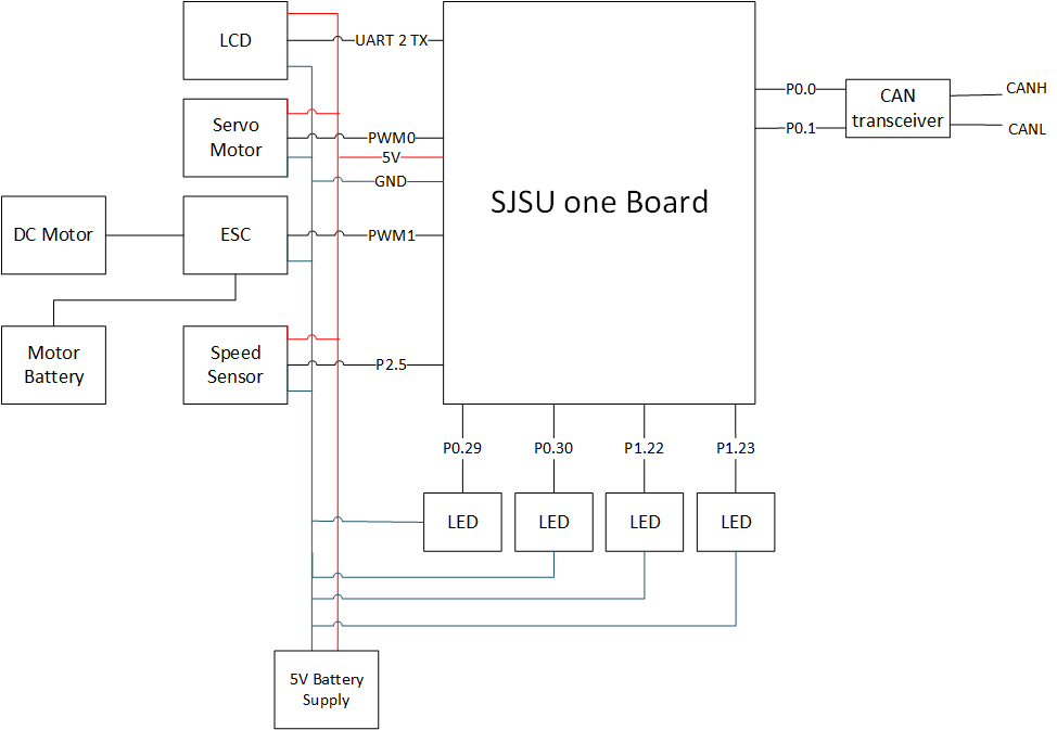
| − | The motor-IO controller consists | + | The motor-IO controller consists of four modules: LCD modules, Servo motor module, DC motor module, and speed sensor module. Steering motor module controls steering of the car; DC motor module controls movement; Speed sensor module reports the rpm of a wheel. |
[[File:CmpE243_F15_Fury_motorIOschematics.bmp| 974px | center| thumb | Schematic for Motor and IO block]] | [[File:CmpE243_F15_Fury_motorIOschematics.bmp| 974px | center| thumb | Schematic for Motor and IO block]] | ||
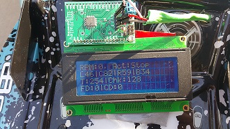
| − | *'''''LCD:''''' : | + | *'''''LCD Module:''''' : Generic 20x4 LCD |
| − | [[File:CmpE243_F15_Fury_basicLCD.jpg| 332px | center| thumb | | + | [[File:CmpE243_F15_Fury_basicLCD.jpg| 332px | center| thumb | LCD Display]] |
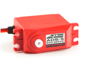
| − | *'''''Servo motor:''''' : Arrma ADS-5 Steering Servo motor, which comes with the car | + | *'''''Servo motor module:''''' : Arrma ADS-5 Steering Servo motor, which comes with the car |
[[File:CmpE243_F15_Fury_ServoMotor.bmp| 176px | center| thumb | Servo Motor]] | [[File:CmpE243_F15_Fury_ServoMotor.bmp| 176px | center| thumb | Servo Motor]] | ||
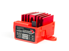
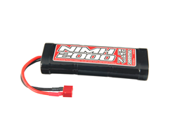
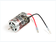
| − | *'''''DC motor:''''' : Arrma 6 cell 2000mAh 7.2 volt NiMh battery pack, Arrma mega waterproof 35A ESC, and a 15T mega brushed motor, which come with the car | + | *'''''DC motor module:''''' : Arrma 6 cell 2000mAh 7.2 volt NiMh battery pack, Arrma mega waterproof 35A ESC, and a 15T mega brushed motor, which come with the car |
[[File:CmpE243_F15_Fury_Esc.bmp| 240px | left| thumb | ESC]] | [[File:CmpE243_F15_Fury_Esc.bmp| 240px | left| thumb | ESC]] | ||
| Line 484: | Line 557: | ||
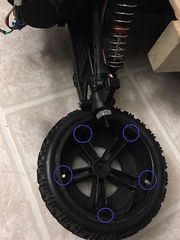
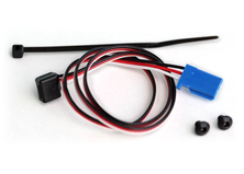
| − | *'''''Speed | + | *'''''Speed Sensor module:''''' :Traxxas 6520 RPM Sensor and magnets |
| + | [[File:CmpE243_F15_Fury_magOnWheel.jpg| 180px | left| thumb | 5 magnetics on wheel ]] | ||
[[File:CmpE243_F15_Fury_SpeedSensor.bmp| 222px | center| thumb | Speed Sensor]] | [[File:CmpE243_F15_Fury_SpeedSensor.bmp| 222px | center| thumb | Speed Sensor]] | ||
| + | |||
| + | |||
| + | |||
| + | |||
| + | |||
| + | |||
| + | |||
=== Hardware Interface === | === Hardware Interface === | ||
| − | |||
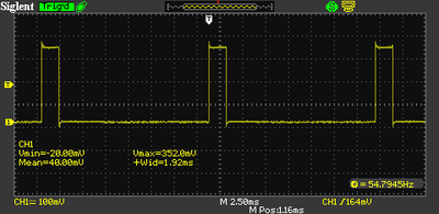
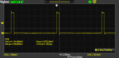
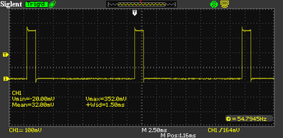
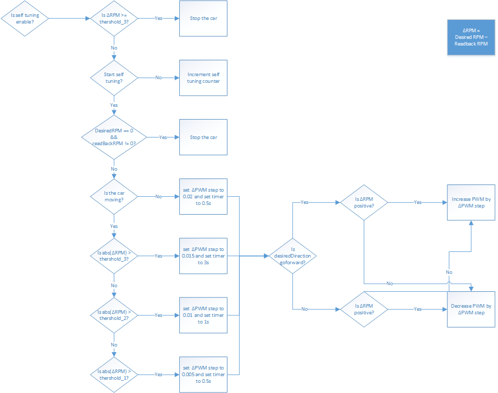
| − | '''CAN''' - Master controller makes decision for motors’ behavior. The decision is sent to motor controller through CAN bus with options that provided by each module. Full can is enabled in motor/IO controller board, which means when the module receives CAN messages, messages are put into ram memory by hardware. Since LCD provides information display screen for each controller on this car, many CAN messages are received. Using normal CAN in this case accumulates the queue in CAN easily and messages with the same message id most likely occurs more than once but only the last one matters. Therefore, full can is a better option since the software can read from the ram for the most recent messages. For motor controller, software reads and analyzes motor messages (message ID 0x20, 0x21 and 0x22) every 0.01s, and send 2 messages to CAN bus every 1s. Following | + | '''CAN''' - Master controller makes decision for motors’ behavior. The decision is sent to motor controller through CAN bus with options that provided by each module. Full can is enabled in motor/IO controller board, which means when the module receives CAN messages, messages are put into ram memory by hardware. Since LCD provides information display screen for each controller on this car, many CAN messages are received. Using normal CAN in this case accumulates the queue in CAN easily and receives messages with the same message id most likely occurs more than once but only the last one matters. Therefore, full can is a better option since the software can read from the ram for the most recent messages. For motor controller, software reads and analyzes motor messages (message ID 0x20, 0x21 and 0x22) every 0.01s, and send 2 messages(message ID 0x100 and 0x102) to CAN bus every 1s. Following DBC file is used to generate CAN messages that is used in motor-io module. |
BO_ 20 RESET_MOTOR: 1 DRIVER | BO_ 20 RESET_MOTOR: 1 DRIVER | ||
| Line 514: | Line 594: | ||
[[File:CmpE243_F15_Fury_MinDutyCycle.BMP| 400px | right | thumb | Minimum Duty Cycle for turning left/going backward]] | [[File:CmpE243_F15_Fury_MinDutyCycle.BMP| 400px | right | thumb | Minimum Duty Cycle for turning left/going backward]] | ||
[[File:CmpE243_F15_Fury_DutyCycle.BMP| 400px | center| thumb | Duty Cycle for going straight/stop]] | [[File:CmpE243_F15_Fury_DutyCycle.BMP| 400px | center| thumb | Duty Cycle for going straight/stop]] | ||
| + | |||
| + | |||
| + | |||
=== Software Design === | === Software Design === | ||
| − | |||
'''Displaying on LCD''' | '''Displaying on LCD''' | ||
| Line 554: | Line 636: | ||
=== Implementation === | === Implementation === | ||
| − | |||
| − | '''LCD''' - | + | '''LCD''' - LCD is used for displaying sensor data and for debugging and tuning purposes. LCD module communicates to SJSUOne Board via Uart (Uart2 Rx and Tx pins in our case). LCD displays the following information:(See photo in Hardware Design) |
| + | 1) RPM calculated with the speed sensor and moving direction | ||
| + | 2) Right, left, center and back sensor readings | ||
| + | 3) Compass Information: Recommended turns and number of check points | ||
| + | 4) Distance to destination and check points | ||
| + | |||
| + | {| class="wikitable" | ||
| + | |+ LCD Module Commands | ||
| + | |- | ||
| + | ! scope="col"| Action | ||
| + | ! scope="col"| Commands | ||
| + | |- | ||
| + | ! scope="col"| Initialize UART | ||
| + | | Uart2::getInstance().init(38400) | ||
| + | |- | ||
| + | ! scope="col"| Sample code for displaying rpm and car action: | ||
| + | | sprintf(buffer, "RPM:%d, Act:%s\n", (int)rpm, stop? "Stop": (isForward? "Fwd": "Back")); | ||
| + | |- | ||
| + | ! scope="col"| Add buffer to printStr | ||
| + | | printStr.append(buffer); | ||
| + | |- | ||
| + | ! scope="col"| Use printf to output data on UART | ||
| + | | Uart2::getInstance().printf(printStr.c_str()); | ||
| + | |- | ||
| + | ! scope="col"| Clear LCD | ||
| + | | Uart2::getInstance().putline("$CLR_SCR"); | ||
| + | |- | ||
| + | |} | ||
'''Speed Sensor''' - This sensor detects magnetic field and outputs a pulse to the microcontroller. In this project, five magnets are attached to the wheel. When the wheel rotates, the magnet gets closer to the sensor and the sensor would generate a pulse. With this pulse, software in the microcontroller can calculate time difference between one pulse and another to get the RPM(rotation per minute). | '''Speed Sensor''' - This sensor detects magnetic field and outputs a pulse to the microcontroller. In this project, five magnets are attached to the wheel. When the wheel rotates, the magnet gets closer to the sensor and the sensor would generate a pulse. With this pulse, software in the microcontroller can calculate time difference between one pulse and another to get the RPM(rotation per minute). | ||
| Line 609: | Line 717: | ||
=== Testing & Technical Challenges === | === Testing & Technical Challenges === | ||
| − | |||
| − | |||
| − | Backward - We did not know how to control the car goes backward. After quite a bit of research and experiment with the car, we found out that the ESC requires two clicks from the remote to change direction. As a result, we simulates it by sending 2 different close-to-base PWM values. | + | * Backward - We did not know how to control the car goes backward. After quite a bit of research and experiment with the car, we found out that the ESC requires two clicks from the remote to change direction. As a result, we simulates it by sending 2 different close-to-base PWM values. |
| − | Brake - Our car does not have a brake. When the base PWM is sent to the ESC. The car will still move forward due to momentum. Master controller | + | * Brake - Our car does not have a brake. When the base PWM is sent to the ESC. The car will still move forward due to momentum. Master controller needs to take this into calculation. We will suggest to pick a car with a brake option. |
| − | Speed sensor - At first, we stick 1 magnetic on the right back wheel and target rpm is 120. This also means about 2 pulses per second is received. Since number of data is too little for each second, the analysis/tuning of speed only can happen every 1 second. To increase the number of data, we stick 5 magnetic in total on the wheel, which means about 10 pulse per second. Now, the analysis/tuning of speed will happen every 0.5 second. | + | * Speed sensor - At first, we stick 1 magnetic on the right back wheel and target rpm is 120. This also means about 2 pulses per second is received. Since number of data is too little for each second, the analysis/tuning of speed only can happen every 1 second. To increase the number of data, we stick 5 magnetic in total on the wheel, which means about 10 pulse per second. Now, the analysis/tuning of speed will happen every 0.5 second. |
| − | Computer program - One of our teammates' computer, was used to program the flash all the time, all of a sudden, causes the board rebooting after loading the program. We tried to load the exact same hex with another computer to the same board, and the board works fine. | + | * Computer program - One of our teammates' computer, was used to program the flash all the time, all of a sudden, causes the board rebooting after loading the program. We tried to load the exact same hex with another computer to the same board, and the board works fine. |
| + | |||
| + | *LCD - We initially planned to use 4D System's 32-PTU LCD. It came with its own GUI interface, called VisieGenie. We faced some problems in getting the GUI to change its value when certain hex codes were sent out on UART. So we decided to go with the simple 20X4 LCD, without a GUI, and display values from sensors early on. | ||
== Sensor Controller == | == Sensor Controller == | ||
| Line 720: | Line 828: | ||
[[File:F15 243 Fury lidar sensor.jpg]] | [[File:F15 243 Fury lidar sensor.jpg]] | ||
| − | The Battery sensor interface was | + | === '''Battery Sensor''' === |
| + | |||
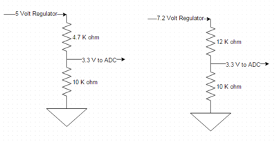
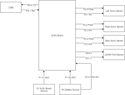
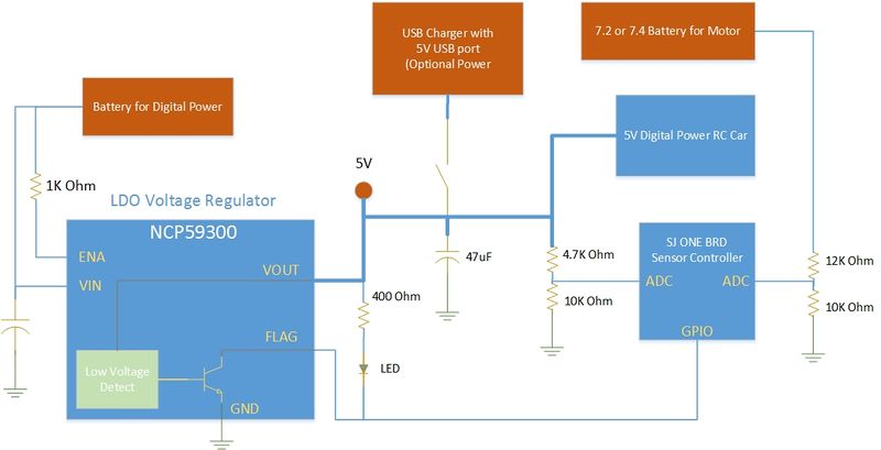
| + | The Battery sensor interface was provided by the 12 bit ADC on the SJ One Board. The ADC has the reference voltage connected to 3.3V and any voltage to be sensed has to be brought down to 3.3V using a resistor divider circuit. The design for the Fury RC car has a 5V source for digital power and a 7.2-7.4 source to power the motor. Both voltages had to be scaled down to 3.3V to interface to the ADC. There are two options to provide a voltage source for the digital circuits. Option 1 was from a NCP59300 LDO Voltage regulator which provides a FLAG output to signal that the 5V wa10% below the nominal 5V. This FLAG signal as well as the reading on the ADC was reported to the master controller. A local LED also provided visual indication that the battery was draining. The second option was to provide the 5V from a USB battery power source which turned out to be the preferred choice since it lasted a long time. Below is a diagram of the power with battery sensing options. | ||
| + | |||
| + | |||
| + | |||
| + | [[File:F15 243 Fury battery sensing.jpg | 800px]]] | ||
| + | |||
| + | === '''Sensor Controller Pin Mapping ''' === | ||
| + | |||
{| class="wikitable" | {| class="wikitable" | ||
|+ Sensor Pin layout | |+ Sensor Pin layout | ||
| Line 767: | Line 884: | ||
For the sensor, we created two tasks to complete the sensor software design. The first task was to initialize the pins for the sonic sensor and create the interrupts for each of the sonic sensors. In the run phase of the task, we trigger the reading pin and use interrupts to get the length in us on the PWM pin. We repeat for each of the three sonic sensors which will have a 45 ms delay between the next triggering of the sonic sensor. The LIDAR is sampled through I2C at the same time as the first sonic sensor it sampled. After all three sonic sensor have data, we applied a simple filter to eliminate bad values. Finally we values from all the sensor are put into a queue that the periodical function will check every 10 Hz and send out a CAN message. | For the sensor, we created two tasks to complete the sensor software design. The first task was to initialize the pins for the sonic sensor and create the interrupts for each of the sonic sensors. In the run phase of the task, we trigger the reading pin and use interrupts to get the length in us on the PWM pin. We repeat for each of the three sonic sensors which will have a 45 ms delay between the next triggering of the sonic sensor. The LIDAR is sampled through I2C at the same time as the first sonic sensor it sampled. After all three sonic sensor have data, we applied a simple filter to eliminate bad values. Finally we values from all the sensor are put into a queue that the periodical function will check every 10 Hz and send out a CAN message. | ||
| − | For the Battery sensor was in a separate task that would be sent out everyone 1 Hz. This task initialized the ADC pins and an interrupt for the flag bit from the voltage regulator. In the run phase we read the value of each ADC and place them in a queue with the flag bit value. To get the voltage level of the battery we took the percentage based on the max ADC value and multiple it by the battery's original value. | + | For the Battery sensor was in a separate task that would be sent out everyone 1 Hz. This task initialized the ADC pins and an interrupt for the flag bit from the voltage regulator. In the run phase we read the value of each ADC and place them in a queue with the flag bit value. To get the voltage level of the battery we took the percentage based on the max ADC value and multiple it by the battery's original value. For debug purpose, we had the voltage level displayed on the SJSUOne board. |
<syntaxhighlight lang="c"> | <syntaxhighlight lang="c"> | ||
BattSen.MotorBattery = ((adc0_get_reading(4)*7.4 * 10) / 4096); | BattSen.MotorBattery = ((adc0_get_reading(4)*7.4 * 10) / 4096); | ||
| Line 836: | Line 953: | ||
=== Testing & Technical Challenges === | === Testing & Technical Challenges === | ||
* For the sonic sensor the biggest challenge was preventing the sensor from interfering with each other. While testing the sensor would get incorrect values if the time between triggering was too short. I notice with a 30 ms delay that the sensor seemed to be working correctly but when an object was placed on the right side of the car the left sensor would react. By placing a delay of 45 ms I was able to only see the right sensor react and the left remain the same. | * For the sonic sensor the biggest challenge was preventing the sensor from interfering with each other. While testing the sensor would get incorrect values if the time between triggering was too short. I notice with a 30 ms delay that the sensor seemed to be working correctly but when an object was placed on the right side of the car the left sensor would react. By placing a delay of 45 ms I was able to only see the right sensor react and the left remain the same. | ||
| + | |||
* The next issue during testing was getting value from the sensor that were greater than the device was capable of having. By applying a simple filter to weed out bad value allows the master only to receive good values. | * The next issue during testing was getting value from the sensor that were greater than the device was capable of having. By applying a simple filter to weed out bad value allows the master only to receive good values. | ||
| + | |||
* During the last stages of testing, we notice that the sensors were receiving low value because it was picking up the ground. To fix the issue we raised the sensors 3 inches and slightly angled them back to increase the range. | * During the last stages of testing, we notice that the sensors were receiving low value because it was picking up the ground. To fix the issue we raised the sensors 3 inches and slightly angled them back to increase the range. | ||
| + | |||
| + | * The Lidar sensor sends a value of 0 when it is out of range. Also, it sends 0 if an object is very close like 1 inch away. To solve this problem, the Lidar sensor was moved back so that it will never read 0 for an object that was too close. For the out of range case, the 0 value was replaced with 600. | ||
== Geographical Controller and Compass == | == Geographical Controller and Compass == | ||
| Line 946: | Line 1,067: | ||
=== Hardware Interface === | === Hardware Interface === | ||
'''GPS module''' | '''GPS module''' | ||
| + | [[File:F15_Fury_GEO_Controller_Compass_reading.jpg|200px|GeoDesign|thumb |right | Compass validation]] | ||
| + | [[File:F15_Fury_GEO_Controller_7_segment_merged.jpg|200px|GeoDesign|thumb |right | 7 segment display]] | ||
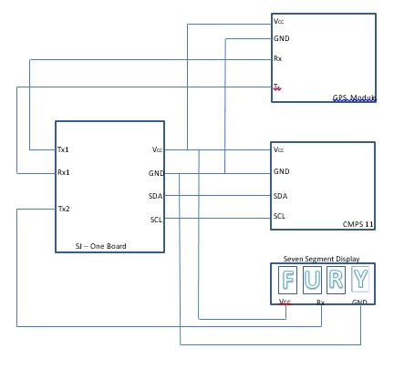
Communication between GPS and SJOne board is through UART2. GPS was configured to communicate at 38400bps and operate at 10Hz. A coin battery of 3.3V was connected between Vbat and Gnd of GPS. The coin battery helped in hot start of GPS module. | Communication between GPS and SJOne board is through UART2. GPS was configured to communicate at 38400bps and operate at 10Hz. A coin battery of 3.3V was connected between Vbat and Gnd of GPS. The coin battery helped in hot start of GPS module. | ||
| Line 951: | Line 1,074: | ||
'''Compass module''' | '''Compass module''' | ||
| − | CMPS 11 module provides two ways of communication. First option is I2C and second option is UART. We chose I2C communication since it is faster when compared to UART. Since GPS uses UART2 and Seven segment display uses UART3 we decided to use I2C. The operating voltage range is from 3.3v to 5v. | + | CMPS 11 module provides two ways of communication. First option is I2C and second option is UART. We chose I2C communication since it is faster when compared to UART. Since GPS uses UART2 and Seven segment display uses UART3 we decided to use I2C. The operating voltage range is from 3.3v to 5v. |
| − | + | '''7 segment display''' | |
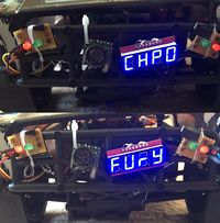
| − | + | UART3 is used to send out commands to 7 segment display. This is used to display the team name and the checkpoint number. | |
| − | + | '''Overview of Geo Controller design''' | |
| + | [[File:F15_Fury_GEO_Controller_GeoDesign.jpg|500px|GeoDesign|thumb |center | Geo Controller & 7 segement display]] | ||
=== Software Design === | === Software Design === | ||
| Line 965: | Line 1,089: | ||
[[File:F15_Fury_GEO_Controller_GPRMC_format.jpg|300px|right|thumb|GPRMC format]] | [[File:F15_Fury_GEO_Controller_GPRMC_format.jpg|300px|right|thumb|GPRMC format]] | ||
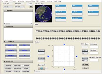
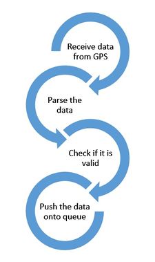
A task is created to read the GPS values from the module. This task starts reading GPS coordinates when there is some data on UART, the received data is then checked if it is valid. If valid, then the data is pushed onto queue which is basically every 200ms, since the GPS module is configured to work at 5Hz. GPS module transmits data in NMEA format and we are following the $GPRMC data. GPS module was configured for pedestrian mode. Module was configured through the software provided by skytraq. Coordinates from communication module is received at the start of code which contains checkpoint details. The GPS data and the checkpoint data is used to calculate the distance to next checkpoint, distance to final destination and angle in which the car has to head by using Haversine formula. Once a checkpoint is reached, the checkpoint is updated and continues till final destination is reached. Once the final destination is reached, master is informed about the same. Present GPS data is transmitted back to communication bridge. | A task is created to read the GPS values from the module. This task starts reading GPS coordinates when there is some data on UART, the received data is then checked if it is valid. If valid, then the data is pushed onto queue which is basically every 200ms, since the GPS module is configured to work at 5Hz. GPS module transmits data in NMEA format and we are following the $GPRMC data. GPS module was configured for pedestrian mode. Module was configured through the software provided by skytraq. Coordinates from communication module is received at the start of code which contains checkpoint details. The GPS data and the checkpoint data is used to calculate the distance to next checkpoint, distance to final destination and angle in which the car has to head by using Haversine formula. Once a checkpoint is reached, the checkpoint is updated and continues till final destination is reached. Once the final destination is reached, master is informed about the same. Present GPS data is transmitted back to communication bridge. | ||
| + | [[File:F15_Fury_GEO_Controller_gps_flowchart.jpg|225px|center]] | ||
'''Compass module''' | '''Compass module''' | ||
| Line 974: | Line 1,099: | ||
* Switch 3 to do the factory reset setting. | * Switch 3 to do the factory reset setting. | ||
| − | Algorithm to calculate distance using longitude and latitude values. | + | '''Calibration of Compass module''' |
| + | |||
| + | [[File:F15_Fury_GEO_Controller_compassCalibration_flowchart.jpg|300px]] | ||
| + | |||
| + | * Purpose of calibration is to remove sensor gain and offset of both magnetometer and accelerometer. | ||
| + | * This is achieved by looking for maximum sensor outputs. | ||
| + | * To enter into calibration mode, we need to send 3 byte sequences 0xF0,0xF5 & 0xF6 to the command register. | ||
| + | * There must be a '''minimum''' of 20ms delay between each I2C frame. | ||
| + | |||
| + | '''Algorithm to calculate distance using longitude and latitude values.''' | ||
| + | |||
| + | * The distance is calculated between 2 geographical points. | ||
| + | * It is used to calculate to distance between two checkpoints in our project. | ||
| + | * We use ‘haversine’ to calculate the distance of two points over a sphere i.e the earths surface. | ||
| + | |||
| + | Haversine formula: | ||
| + | a = sin²(Δφ/2) + cos φ1 ⋅ cos φ2 ⋅ sin²(Δλ/2) | ||
| + | c = 2 ⋅ atan2( √a, √(1−a) ) | ||
| + | d = R ⋅ c | ||
| + | |||
| + | where φ is latitude, λ is longitude, R is earth’s radius (mean radius = 6,371km) (assuming earth to be a sphere and ignoring ellipsoidal effects) | ||
| + | |||
| + | '''Algorithm to calculate desired heading using longitude and latitude values.''' | ||
| + | |||
| + | * This algorithm is used to calculate the desired heading direction between two geographical locations. This helps in navigating car to reach the destination. | ||
| + | * The algorithm calculates the heading between present checkpoint and the next checkpoint by taking the present latitude and longitude values and the next checkpoint's latitude and longitude values. | ||
| + | * The final heading direction may change when we travel towards the destination because of the shape of earth. Hence, the forward azimuth formula is used to calculate the initial direction. | ||
| + | * To get the final direction, take bearing from the end point to the start point and reverse it as follows, θ = (θ+180) % 360 | ||
| − | + | Formula: | |
| + | θ = atan2( sin Δλ ⋅ cos φ2 , cos φ1 ⋅ sin φ2 − sin φ1 ⋅ cos φ2 ⋅ cos Δλ ) | ||
| + | |||
| + | where φ is latitude, λ is longitude | ||
| + | |||
| + | Since this formula generates a negative value (-180 to 180), we need to normalize the value to get a compass bearing (0 - 360). We have divided the compass into 12 zones of 30 degrees each. This allows the car to remain in one zone and only turn if a heading / turn of more than 30 degrees is to be performed. This provides stability to the car thereby avoiding heading correction every time the algorithm computes a heading. | ||
| + | |||
| + | [[File:F15_Fury_GEO_Controller_bearing.jpg|250px|left|thumb|Turn decision]] | ||
| + | <br> | ||
| + | <br> | ||
| + | <br> | ||
| + | <br> | ||
| + | <br> | ||
| + | <br> | ||
| + | <br> | ||
| + | <br> | ||
| + | <br> | ||
| + | <br> | ||
| + | <br> | ||
| + | <br> | ||
| + | <br> | ||
| + | <br> | ||
| + | <br> | ||
| + | * The circle is divided into 12 zones (360/30 = 12). | ||
| + | * If the desired heading is greater than 30 degree then a decision is made to turn right. | ||
| + | * If the desired heading is greater than 90 degree then a decision is made to take a U - turn. | ||
| + | * If the angle is between 330 degrees to 0 degrees and from 0 degrees to 30 degrees then car heads straight. | ||
| + | * Only if the desired heading is not in between these ranges then a decision is made to turn the car. | ||
| + | |||
| + | |||
| + | |||
| + | |||
| + | <div style="text-align: center;"> '''Two different threads which run concurrently''' </div> | ||
| + | [[File:F15_Fury_GEO_Controller_geoController_flowchart.jpg|500px|center]] | ||
=== Controller Communication Table === | === Controller Communication Table === | ||
| + | |||
| + | DBC file, used to generate structures that can be used in the code. Since we had already implemented with our own structures, we did not use DBC for our project. | ||
| + | |||
| + | BO_ 160 HEARTBEAT: 0 GEO | ||
| + | SG_ GEO_HEARTBEAT_cmd : 0|0@1+ (1,0) [0|0] "" DRIVER | ||
| + | BO_ 162 HEADING: 6 GEO | ||
| + | SG_ GEO_HEADING_turnangle : 0|8@1+ (1,0) [0|0] "" MASTER, IO | ||
| + | SG_ GEO_HEADING_checkpoint : 8|7@1+ (1,0) [0|0] "" MASTER, IO | ||
| + | SG_ GEO_HEADING_isfinal : 15|1@1+ (1,0) [0|0] "" MASTER, IO | ||
| + | SG_ GEO_HEADING_distancetofinaldestination : 16|16@1+ (1,0) [0|0] "" MASTER, IO | ||
| + | SG_ GEO_HEADING_distancetonextcheckpoint : 32|16@1+ (1,0) [0|0] "" MASTER, IO | ||
| + | BO_ 461 LOCATION: 8 GEO | ||
| + | SG_ GEO_LOCATION_latitudeDecimal : 0|8@1+ (1,0) [0|0] "" COMMUNICATIONBRIDGE, IO | ||
| + | SG_ GEO_LOCATION_latitudeFloat : 8|20@1+ (1,0) [0|0] "" COMMUNICATIONBRIDGE, IO | ||
| + | SG_ GEO_LOCATION_longitudeDecimal : 28|8@1+ (1,0) [0|0] "" COMMUNICATIONBRIDGE, IO | ||
| + | SG_ GEO_LOCATION_longitudeFloat : 36|20@1+ (1,0) [0|0] "" COMMUNICATIONBRIDGE, IO | ||
| + | SG_ GEO_LOCATION_checkpoint : 56|7@1+ (1,0) [0|0] "" COMMUNICATIONBRIDGE, IO | ||
| + | SG_ GEO_LOCATION_isFinal : 63|1@1+ (1,0) [0|0] "" COMMUNICATIONBRIDGE, IO | ||
| + | BO_ 47F ACK: 0 GEO | ||
| + | SG_ GEO_ACK_cmd : 0|0@1+ (1,0) [0|0] "" COMMUNICATIONBRIDGE | ||
| + | |||
{| class="wikitable" | {| class="wikitable" | ||
| Line 1,009: | Line 1,215: | ||
! scope="col"| 3 | ! scope="col"| 3 | ||
| 0x461 | | 0x461 | ||
| − | | Communication Bridge | + | | Communication Bridge and I/O |
| GPS DATA | | GPS DATA | ||
| | | | ||
| Line 1,029: | Line 1,235: | ||
=== Testing & Technical Challenges === | === Testing & Technical Challenges === | ||
| − | |||
| − | |||
| + | [[File:F15_Fury_GEO_Controller_10Hz_update.png|270px|left|thumb|During 10Hz update of GPS]] | ||
| + | [[File:F15_Fury_GEO_Controller_5Hz_update.png|270px|right|thumb|During 5Hz update of GPS]] | ||
| + | '''For Debug purpose:''' | ||
On board LED 3 is toggled every time there is an error to push the data onto queue. | On board LED 3 is toggled every time there is an error to push the data onto queue. | ||
| + | |||
On board LED 4 is toggled every time the data is not read from gps. | On board LED 4 is toggled every time the data is not read from gps. | ||
| − | + | Different numbers were displayed on the 7 segment display of SJOne board to debug the compass modes. | |
| + | |||
| + | ''FURY'' was displayed on 7 segment display of SJOne board on a rolling basis to indicate the destination was reached. | ||
| + | |||
| + | '''Testing Procedure''' | ||
| + | * The checkpoints were added once, manually at the start of the code. The checkpoint data was collected from the android app at different locations. | ||
| + | * Distance calculations(next checkpoint distance and final distance) were tested by using these test values of latitude and longitude. | ||
| + | * Desired heading angle was also calculated on similar lines. | ||
| + | * GPS was carried along with the SJOne board to these checkpoints and was checked for the update of checkpoint data in software. | ||
| + | * Compass heading angle and desired angle was also mapped similarly. | ||
| + | * SJOne board was connected to CAN bus and was checked if the messages were sent through CAN bus by using a CAN analyzer tool from microchip. | ||
| + | |||
| + | '''Challenges:''' | ||
| + | * Initial fix for GPS used to take a lot of time. At first, it took around 1 hour and 30 minutes to get a fix. Then understood that GPS wont fix to a satellite if it is in a closed environment. Then tried to get a fix outside and it took around 30 minutes which is better but still not good. After reading a lot about the working of hot start mode in GPS module, we figured out that Vbat of around 3V has to be connected. This improved the time to get a satellite fix and it reduced to around less than 2 minutes. | ||
| + | * When the car was carried around the update of GPS was correct and car worked as desired, the problem was when the car was let lose on road. The car never used to go straight. To avoid this, kalman filter was implemented and then tested. There was no much changes since IMU was not used and many other factors was not considered to factor in kalman filter. The GPS was then slowed down by configuring it to update at 5Hz, this stabilized the car. The figures provide the movement of car with GPS update rate of 5Hz and 10Hz. | ||
| + | * Don't use 5v supply because for us it somehow created more than expected offset and our initial testing failed because of it. Later we switched back to 3.3v and offset was in expected range and testing went well too. | ||
| + | * If any objects such as laptop or mobile was taken near compass, the calibration would be lost and compass had to be re-calibrated. Since there was no software calibration available on the board, we had to manually remove the compass from the car, send calibration commands and then calibrate it. After few days, we tried factory reset commands which brought back the compass to correct readings, this was integrated in our code to reset the compass through android app by send messages through CAN bus. This reduced a lot of work for us. | ||
== Android & Communication Bridge Controller == | == Android & Communication Bridge Controller == | ||
| Line 1,122: | Line 1,346: | ||
=== Hardware Design === | === Hardware Design === | ||
| − | |||
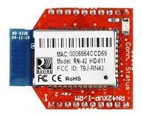
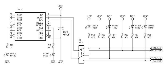
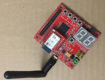
*For wireless communication between the SJSU One Board and a Android device, a Bluetooth (RN-421) module is used. This module was chosen because it can connect and mount directly onto the SJSU One Board's XBee breakout socket. | *For wireless communication between the SJSU One Board and a Android device, a Bluetooth (RN-421) module is used. This module was chosen because it can connect and mount directly onto the SJSU One Board's XBee breakout socket. | ||
| Line 1,141: | Line 1,364: | ||
<b>2. Nordic Wireless:</b><br> | <b>2. Nordic Wireless:</b><br> | ||
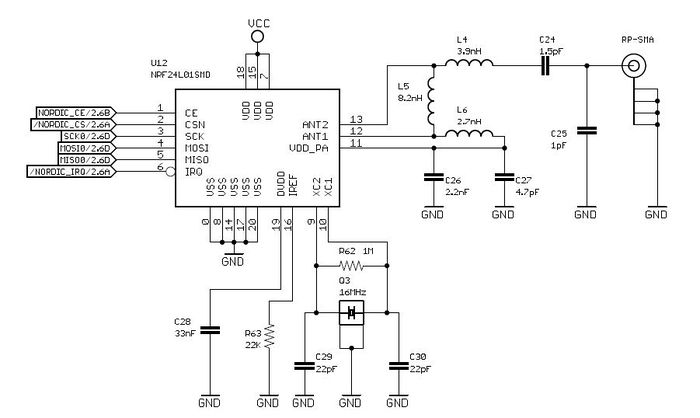
| − | + | [[File:F15_Fury_Communication_Bridge_Wireless_Module.jpg|350px|right|thumb|Wireless Module]] | |
Features: | Features: | ||
*Worldwide 2.4GHz ISM band operation. | *Worldwide 2.4GHz ISM band operation. | ||
| Line 1,152: | Line 1,375: | ||
=== Hardware Interface === | === Hardware Interface === | ||
| − | In | + | |
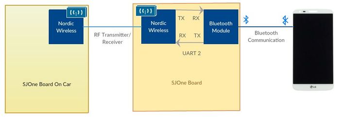
| + | <b>Bridge between Nodic wireless and bluetooth:</b><br> | ||
| + | <p style="text-indent: 1em; text-align: justify;"> | ||
| + | Communication between Android Application and the Communication bridge is through Bluetooth. In order to increase the range and to give a stable uninterrupted communication, we further split the communication bridge. One Node (SJone board) receives the data via Bluetooth-uart interface, which processes the command sent gets the data parses it and reroutes the data to CAN Node via Nordic wireless. The data from the received wireless packets is sent over CAN bus with appropriate message IDs. | ||
| + | </p> | ||
[[File:F15_Fury_Communication_Bridge_Block_Diagram.jpg|700px|center|thumb|System Block Diagram]] | [[File:F15_Fury_Communication_Bridge_Block_Diagram.jpg|700px|center|thumb|System Block Diagram]] | ||
=== Software Design === | === Software Design === | ||
| − | + | === Git === | |
| + | Since Communication Bridge module contains both Android App and LPC1758_FreeRTOS project, we created following folder structure. | ||
| + | |||
| + | *LPC1758_freertos | ||
| + | ** Android- Android Project | ||
| + | ** LPC1758_Communication_Bridge- which contained the freertos project for LPC1758 | ||
| + | |||
| + | ==='''Implementation''' === | ||
| + | |||
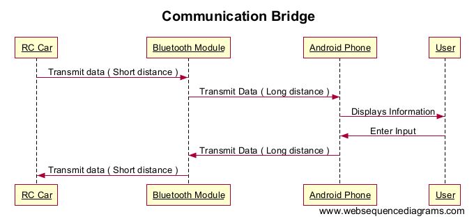
| + | Implementation for this module consists the development of : | ||
| + | |||
| + | 1. Android App | ||
| + | |||
| + | 2. CAN-Bluetooth communication bridge | ||
| + | |||
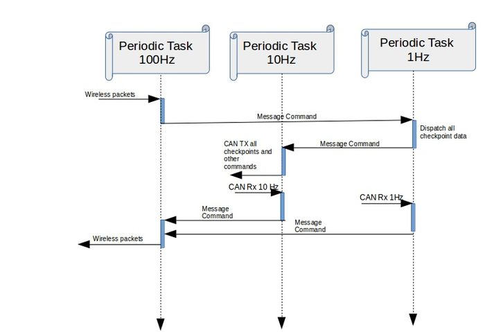
| + | Below is the System Sequence Diagram: | ||
| + | |||
| + | [[File:F15_Fury_Communication_Bridge_sequence _Diagram.jpg|700px|center|thumb|System Sequence Diagram]] | ||
| + | |||
| + | === '''Android App'''=== | ||
| + | |||
| + | Android App using Java and android application framework(API 22). The map activity is implemented with the integration of google map. Bluetooth connectivity is realized with the help of Bluetooth API's provided alongside the framework for the RF communication. For asynchronous message passing within the application,handler package is used.To access the checkpoints we are using Google direction API and JSON parser to parse the data received. | ||
| + | |||
| + | {| class="wikitable" | ||
| + | |+ Commands Sent from Android App | ||
| + | |- | ||
| + | ! scope="col"| S.R. | ||
| + | ! scope="col"| Command | ||
| + | ! scope="col"| Code | ||
| + | |||
| + | |- | ||
| + | |||
| + | ! scope="col"| 1 | ||
| + | | Start | ||
| + | | start$ | ||
| + | |||
| + | |- | ||
| + | ! scope="col"| 2 | ||
| + | | Checkpoints | ||
| + | | check <Lattitude> <Longitude> <Checkpoint Number> <IsFinal>$ | ||
| + | |||
| + | |} | ||
| + | |||
| + | === '''CAN-Bluetooth communication bridge'''=== | ||
| + | [[File:F15_Fury_Communication_Bridge_Node.jpg|150px|right|thumb|Node Switch Macro]] | ||
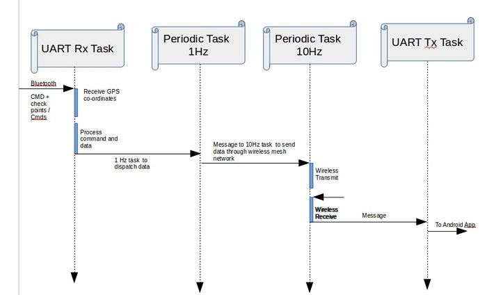
| + | Interface consists of two wireless nodes. One node, gets the input commands from the Android App via Bluetooth, processes the received command and data, to relay it over Nordic wireless mesh network. Second Node receives the wireless packets, gets the data and sends it to the GPS module over can bus. Similarly, The CAN node taps the CAN messages for compass , GPS Location and distance and keeps transmitting the data back to Android App over the same network. The detailed sequence diagram is given below. | ||
| + | As the code for the both the nodes in the communication bridge is in the same source, we used a macro to switch between them. When the NODE_BLUETOOTH is 1, the bluetooth .hex file is flashed. Similarly when the NODE_CAN is 1, the respective .hex file is flashed. | ||
| + | |||
| + | [[File:F15_Fury_Communication_Bridge_Bluetooth_Sequence_Diagram.jpg|700px|center|thumb|Bluetooth Module Sequence Diagram]] | ||
| + | |||
| + | [[File:F15_Fury_Communication_Bridge_Wireless_Sequence_Diagram.jpg|700px|center|thumb|Can Communication Bridge Sequence Diagram]] | ||
| + | |||
| + | |||
| + | When data is sent over Bluetooth to Android App it follows the format as given in the table below. Here the '~' is given a delimiter to mark the end of the command. | ||
| + | |||
| + | {| class="wikitable" | ||
| + | |+ Commands Sent from Communication Bridge to Android App | ||
| + | |- | ||
| + | ! scope="col"| S.R. | ||
| + | ! scope="col"| Command | ||
| + | ! scope="col"| Code | ||
| + | |||
| + | |- | ||
| + | |||
| + | ! scope="col"| 1 | ||
| + | | Acknowledgement | ||
| + | | a~ | ||
| + | |||
| + | |- | ||
| + | ! scope="col"| 2 | ||
| + | | Location Values from Car | ||
| + | | l<Lattitude> <Longitude>~ | ||
| + | |- | ||
| + | ! scope="col"| 3 | ||
| + | | Compass Values from Car | ||
| + | | c<Heading Angle> <Desired Angle> <Turn Direction>~ | ||
| + | |- | ||
| + | ! scope="col"| 4 | ||
| + | | Distance Values from Car | ||
| + | | d<Next Checkpoint Distance> <Final Distance >~ | ||
| + | |||
| + | |} | ||
| + | |||
| + | === '''Communication Bridge CAN message'''=== | ||
| + | To communicate with the other boards, we used the below CAN messages. Below is each of the CAN messages in DBC format. | ||
| + | |||
| + | |||
| + | BO_ 180 HEARTBEAT: 1 CommunicationBridge | ||
| + | SG_ CommunicationBridge_HEARTBEAT_cmd : 0|8@1+ (1,0) [0|0] "" DRIVER | ||
| + | BO_ 181 Drive_Mode: 1 CommunicationBridge | ||
| + | SG_ CommunicationBridge_DriveMode_cmd : 0|8@1+ (1,0) [0|0] "" DRIVER | ||
| + | BO_ 182 STOP: 1 CommunicationBridge | ||
| + | SG_ CommunicationBridge_STOP_cmd : 0|8@1+ (1,0) [0|0] "" DRIVER | ||
| + | BO_ 382 LOCATION: 8 CommunicationBridge | ||
| + | SG_ CommunicationBridge_LOCATION_latitudeDecimal : 0|8@1+ (1,0) [0|0] "" GEO | ||
| + | SG_ CommunicationBridge_LOCATION_latitudeFloat : 8|20@1+ (1,0) [0|0] "" GEO | ||
| + | SG_ CommunicationBridge_LOCATION_longitudeDecimal : 28|8@1+ (1,0) [0|0] "" GEO | ||
| + | SG_ CommunicationBridge_LOCATION_longitudeFloat : 36|20@1+ (1,0) [0|0] "" GEO | ||
| + | SG_ CommunicationBridge_LOCATION_checkpoint : 56|7@1+ (1,0) [0|0] "" GEO | ||
| + | SG_ CommunicationBridge_LOCATION_isFinal : 63|1@1+ (1,0) [0|0] "" GEO | ||
| + | BO_ 385 STOP: 1 CommunicationBridge | ||
| + | SG_ CommunicationBridge_CompassFactoryReset_cmd : 0|8@1+ (1,0) [0|0] "" GEO | ||
| + | |||
| + | |||
{| class="wikitable" | {| class="wikitable" | ||
|+ Communication Bridge + Android Controller Communication Table | |+ Communication Bridge + Android Controller Communication Table | ||
| Line 1,176: | Line 1,506: | ||
|- | |- | ||
! scope="col"| 2 | ! scope="col"| 2 | ||
| − | | | + | | 0X181 |
| Master | | Master | ||
| DRIVE MODE | | DRIVE MODE | ||
| | | | ||
| − | + | No DATA | |
| + | |- | ||
| + | ! scope="col"| 3 | ||
| + | | 0X182 | ||
| + | | Master | ||
| + | | STOP | ||
| + | | | ||
| + | No DATA | ||
| + | |||
|- | |- | ||
| − | ! scope="col"| | + | ! scope="col"| 4 |
| − | | | + | | 0x382 |
| Master | | Master | ||
| LOCATION POINTS | | LOCATION POINTS | ||
| Line 1,190: | Line 1,528: | ||
Msg : 20 bits : latitude_float_part | Msg : 20 bits : latitude_float_part | ||
Msg : 8 bits : longitude_decimal_part | Msg : 8 bits : longitude_decimal_part | ||
| − | Msg : 20 bits : | + | Msg : 20 bits : longitude_decimal_part |
| − | Msg : | + | Msg : 7 bits : checkpoint |
| + | Msg : 1 bit : isFinal | ||
|- | |- | ||
| + | |- | ||
| + | ! scope="col"| 5 | ||
| + | | 0X385 | ||
| + | | Master | ||
| + | | Compass Factory Reset (Debug) | ||
| + | | | ||
| + | No DATA | ||
|} | |} | ||
| − | === | + | === Andriod Application Features === |
| − | + | ||
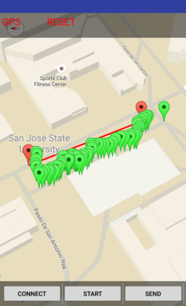
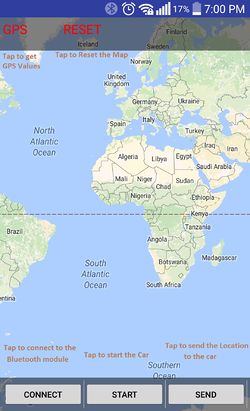
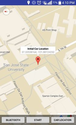
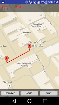
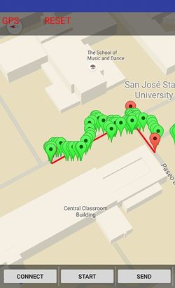
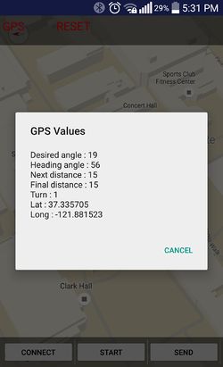
| + | The Android App sends the destination & intermediate checkpoints to the car. It also receives the initial co-ordinates of the car and its further location coordinates as it navigates towards the destination. The intermediate checkpoints is got via Google direction API. The App Interface consists of a Bluetooth connect button - which connects to the Bluetooth module, Send button - which sends all the checkpoint data, Start button - to set the car in drive mode. Reset button - resets the map and marks the 'now' location of the car. GPS button- Shows the co-ordinates data, heading angle, desired angle, distance to next checkpoint, distance to final checkpoint, and turn direction. | ||
| + | |||
| + | Following are the screen shots for the features implemented: | ||
| + | |||
| + | <table> | ||
| + | <tr> | ||
| + | <td valign="top" align="center"> | ||
| + | [[File:F15_Fury_Communication_Bridge_Application.jpg|250px]]<br> | ||
| + | Start Screen | ||
| + | </td> | ||
| + | <td> | ||
| + | </td> | ||
| + | <td valign="top" align="center"> | ||
| + | [[File:F15_Fury_Communication_Bridge_Initial_Location.jpg|250px]]<br> | ||
| + | Initial Location | ||
| + | </td> | ||
| + | <td> | ||
| + | </td> | ||
| + | <td> | ||
| + | </td> | ||
| + | <td valign="top" align="center"> | ||
| + | [[File:F15_Fury_Communication_Bridge_Set_Location.jpg|230px]]<br> | ||
| + | Set Destination Location | ||
| + | </td> | ||
| + | <td> | ||
| + | </td> | ||
| + | <td> | ||
| + | </td> | ||
| + | |||
| + | <td valign="top" align="center"> | ||
| + | [[File:F15_Fury_Communication_Bridge_Car_Location.jpg|250px]]<br> | ||
| + | Dynamic Mark of Car Location | ||
| + | </td> | ||
| + | <td> | ||
| + | </td> | ||
| + | <td> | ||
| + | </td> | ||
| + | <td valign="top" align="center"> | ||
| + | [[File:F15_Fury_Communication_Bridge_GPS_Values.jpg|250px]]<br> | ||
| + | Display GPS Values | ||
| + | </td> | ||
| + | </tr> | ||
| + | </table> | ||
=== Testing & Technical Challenges === | === Testing & Technical Challenges === | ||
| − | + | * Using the existing terminal task present in the FreeRTOS project – Initially we used the existing terminal task to process the command sent from the from the app to the Bluetooth module interfaced through Uart. Terminal Task was hooked to Uart0, and this was changed to Uart2. Doing this resulted in removal of existing terminal based debugging and also there was no return communication back to the android app. Hence, we used Uart2 Tx task to process the incoming commands. | |
| − | + | [[File:F15_Fury_Communication_Bridge_Kill_Board.jpg|200px|right|thumb|Testing Node]] | |
| + | * Getting Initial location from GPS on Android phone – Doing this created a lot of offset from the location that was obtained to the actual location of the car. Therefore we tapped the CAN messages sent out by GPS module on the car to be sent out to the android App. The messages were tapped continuously at a frequency of 1Hz to display on the App. This gave a trace of the cars location on the App, and was used to debug and restart the GPS module on the car whenever there was discrepancy in the location co-ordinates obtained from the GPS module and explained the behavior of the car at times. | ||
| + | |||
| + | * Expanding the range and stabilizing communication between App and Car – Since we used a two way communication between the App and car, we faced two problems 1) range of the bluetooth connection from App to car was short, so when the car is in motion there was dis-connectivity in the communication channel, resulting in manual re-connection every time. Solution to this was to use another wireless channel which gives a stable, long range channel for communication. We used two nodes, one which communicates with Android App via Bluetooth and the other node is the CAN node on the car. The two nodes were connected by a wireless channel through the existing on board Nordic wireless module and Nordic mesh stack. Doing this there was only a loss in wireless packets but never a dis-connectivity in the communication channel. | ||
| + | |||
| + | * For the purpose of testing we used bluetooth node as follows: | ||
| + | ** Kill Switch(Switch 4): When the kill switch is pressed a message is sent to the master to reset all the other boards. This was helpful during the testing when collisions or unanticipated events occurred. | ||
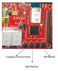
| + | ** Start Switch(Switch 2): Using the start switch the car can be started without giving any location. This was useful when testing indoors as location was not available. | ||
| + | ** Compass Factory Reset switch(Switch 1): This switch was used to perform a factory reset for the compass. During calibration of the compass this switch was extensively used. | ||
== Integration == | == Integration == | ||
=== Testing & Technical Challenges === | === Testing & Technical Challenges === | ||
| − | |||
| − | |||
| − | |||
| − | |||
| − | |||
| − | |||
| − | |||
==== Issue 1: ==== | ==== Issue 1: ==== | ||
| Line 1,217: | Line 1,607: | ||
'''Solution''' - The Full CAN messages had to be added in ascending order. Once this was implemented, the working was smooth. | '''Solution''' - The Full CAN messages had to be added in ascending order. Once this was implemented, the working was smooth. | ||
| + | |||
| + | ==== Issue 2: ==== | ||
| + | The car used to turn even if the destination was straight ahead. There was a bit of difficulty to debug this issue. We could not figure out if it was due to GPS, compass or sensors. The front left and right sensors were mounted a bit low on the car and the readings from the sensors were low, due to reflections from ground, and hence there was difficulty in tuning threshold levels for obstacle avoidance. | ||
| + | |||
| + | '''Solution''' - The sensors were mounted a bit higher and was tilted backwards which gave a good range. The issue was debugged through LCD display and android app. All the important values were displayed on LCD and the android app provided better visualization of the GPS position. | ||
== Conclusion == | == Conclusion == | ||
| − | + | A self-driving car was successfully designed,implemented and tested.The design was changed multiple times during the course of the project. While the final product is not perfect, autonomous navigation of the car has been achieved. If some more time was available , we would have improved the car navigation and added more features. Given a single destination, or multiple checkpoints, the car can successfully navigate to the final destination avoiding all obstacles in its path. | |
| + | |||
| + | This project was a great learning experience since it covered all aspects of a product design: mechanical design and assembly, procurement of parts, software design, coding and testing, and team work. | ||
| + | |||
| + | |||
| + | '''Word of advice: ''' | ||
| + | * Invest time in debugging tools and options, it will save a lot of time while testing. | ||
| + | * Use Telemetry to check variable values than ''printf'' statement. | ||
| + | * Use LCD to display all important messages/values. | ||
| + | * Try to develop an android device such that all the messages are update on the app, it will be handy to check the updated values and for debugging. | ||
| + | * Start testing early to figure out the problems and tune your car for better results. | ||
| + | * CAN analyzer was a great tool to check the CAN messages on CAN bus. This helped in resolving on which board the problem resided. | ||
=== Project Video === | === Project Video === | ||
| − | + | [https://www.youtube.com/watch?v=EUxPC0gf8T8 '''To watch our project video, click here'''] | |
=== Project Source Code === | === Project Source Code === | ||
| − | * [https:// | + | * [https://gitlab.com/christopher.laurence/lpc1758_freertos/branches GitLabSource Code Link] |
== References == | == References == | ||
| + | |||
| + | *Preetpal Kang's lecture notes of CMPE 243, Computer Engineering, San Jose State University, Aug-Dec 2015. | ||
| + | *[http://www.socialledge.com/sjsu/index.php?title=Realtime_OS_on_Embedded_Systems#Fall_2014 Fall 2014 Wiki Projects] | ||
| + | *[http://www.microchip.com/wwwproducts/Devices.aspx?dDocName=en010405 CAN Transceiver] | ||
| + | *[https://www.adafruit.com/products/746 Adafruit Ultimate GPS Breakout - 66 channel w/10 Hz updates - Version 3] | ||
| + | *[http://gis.stackexchange.com/questions/29605/distance-calculation-integrating-incremental-gps-data GPS data calculation accuracy] | ||
| + | *[http://www.csgnetwork.com/gpsdistcalc.html GPS Longitude Latitude distance calculator] | ||
| + | *[http://stackoverflow.com/questions/365826/calculate-distance-between-2-gps-coordinates Calculate distance between two points] | ||
| + | *[https://www.micropik.com/PDF/HCSR04.pdf HCSR04 Ultrasonic Sensor] | ||
| + | *Android Developers manual | ||
| + | *[https://www.codecademy.com/learn/learn-git Learning Git Tutorials] | ||
=== Acknowledgement === | === Acknowledgement === | ||
| − | + | We would like to thank our instructor Preet for always inspiring, encouraging and guiding us to learn and build cool projects related to embedded systems. We really appreciate his patience. This was our first exposure to CAN bus communication and we learned a lot about it. We would also like to thank all our team members for helping each other out while working on this project. Special thanks to Julio Fuentes for designing the hardware frame. | |
| − | |||
| − | |||
| − | |||
=== Appendix === | === Appendix === | ||
* Laser Distance Sensor [[File:F15 243 Fury Lidar spec.pdf]] | * Laser Distance Sensor [[File:F15 243 Fury Lidar spec.pdf]] | ||
| + | * Sonic Sensor [[File:CmpE243_F15_Fury_XL-MaxSonar-EZ_Datasheet.pdf]] | ||
Latest revision as of 20:25, 5 January 2016
Contents
- 1 Project Title
- 2 Abstract
- 3 Schedule
- 4 Parts List & Cost
- 5 Introduction
- 6 Overview
- 7 The Controllers
- 8 Design & Implementation
- 9 Master Controller
- 10 Motor and I/O controller
- 11 Sensor Controller
- 12 Geographical Controller and Compass
- 13 Android & Communication Bridge Controller
- 14 Integration
- 15 Conclusion
- 16 References
Project Title
Fury a self driving RC car
Abstract
This project implements a self-driving car with the ability to have programmable routes and do obstacle avoidance. Programmable routes are implemented through an Android application, while precise motion to a programmed destination is implemented by using an electronic compass and GPS. Also, the self-driving car provides an RPM speed controlled motor for constant speed in different terrains as well as a master controller with obstacle avoidance algorithms and steering control to direct the car to its final destination.
Schedule
| Sl. No | Start Date | End Date | Task | Actual End date |
|---|---|---|---|---|
| 1 | 09/20/2015 | 09/27/2015 | Buy RC Car | 09/26/2015 |
| 2 | 09/27/2015 | 10/3/2015 | Divide the modules among team members | 10/2/2015 |
| 3 | 10/3/2015 | 10/10/2015 | Decide the pins used by each module | 10/15/2015 |
| 4 | 10/10/2015 | 10/25/2015 | Get the main board ready which connects all SJOne boards | 10/20/2015 |
| 5 | 10/3/2015 | 10/30/2015 | Work on individual modules | 11/15/2015 |
| 6 | 10/31/2015 | 11/13/2015 | Sensors, motors and master controller are integrated and tested.
GPS, android and master are integrated and tested |
12/05/2015 |
| 7 | 11/14/2015 | 12/10/2015 | Integration, testing and tweaking | 12/16/2015 |
| 8 | 12/16/2015 | 12/16/2015 | Final testing | 12/16/2015 |
Parts List & Cost
Introduction
This project is aimed at developing a RC car with a self-drive capability based on controller interaction over the CAN (Controller Area Network) bus. This car can steer itself through co-ordinates fed by Google maps and correct its course when it sees an obstacle. To achieve this objective, we plan to integrate 5 controllers dedicated to specific roles that can pass messages over a common CAN communication bus. In addition, the prototype would involve an Android mobile application for data monitoring and controlling, to keep a track of the car remotely and feed it the required checkpoints to reach its destination. Through the android app, user can feed in the desired destination through google maps interface. The car would follow based on co-ordinates and heading provided by its GPS and compass respectively.
Overview
- The GPS would wait for a satellite fix, upon getting a fix, the controller would relay the information over the CAN bus to Android device through its controller.
- Through the android app co-ordinates of destination has to be selected by dropping a marker on the map.
- The android app would calculate all the intermediate checkpoints wherever there are turns.
- These checkpoints are sent over to the geo controller module.
- Upon send a command issued by android app, the master would send a command to the motor control to move forward.
- Any obstacle detected by the ultrasonic sensors would override the current path and try to avoid the obstacle.
- The master controller would compute the course correction and reconfigure the required controllers once the car has passed the obstacle.
- The IO controller is responsible for monitoring the data on the CAN bus and displaying the information on the mounted LCD panel.
- Stop trigger can be given to the car remotely.
- Once the car reaches the first checkpoint, it will update to the next checkpoint automatically. In this way, the process continues till the car reaches the destination.
The Controllers
- Master Controller
- Bhargava Sreekantappa Gayathri
- Thiruparan Balachandran
- Motor and I/O controller
- Sin Yu Ho
- Nimmi Bhatt
- Sensor Controller
- Christopher Laurence
- Julio Fuentes
- Geographical Controller and Compass
- Android & Communication Bridge Controller
Design & Implementation
CAN Interface
The CAN interface was implemented by using the MPC2562 transceiver. The MPC2562 transceiver supports data rates up to 1Mbps and also provides a separate I/O supply pin to support 1.8-5V signaling on the controller side. Below is a diagram of the CAN interface implemented on Fury.
A very useful tool for debugging CAN bus. The CAN BUS Analyzer Tool is intended to be a simple-to-use, low-cost CAN Bus monitor which can be used to develop and debug a high-speed CAN network. The CAN Analyzer tool supports CAN 2.0b and ISO 11898-2 (high-speed CAN with transmission rates of up to 1 Mbit/s). The tool can be connected to the CAN network using the USB connector.
CAN 11-bit ID Format
| DST | SRC | MSG |
|---|---|---|
| 3 bits (11-9) | 3 bits (8-6) | 5 bits (5-0) |
Controller ID Table
| Controller ID | Controller Type |
|---|---|
| 000 | Motor and LCD Controller |
| 001 | Master Controller |
| 010 | Sensor Controller |
| 011 | GPS and compass Controller |
| 100 | Communication Bridge + Android Controller |
Master Controller
Group Members
- Bhargava Sreekantappa Gayathri
- Thiruparan Balachandran
Schedule
| Sl.No | Start Date | End Date | Task | Status | Actual Completion date | Problems Encountered |
|---|---|---|---|---|---|---|
| 1 | 9/27/2015 | 10/4/2015 | Decide on Node address and message ID's for CAN controller. | Completed | 10/1/2015 | |
| 2 | 10/4/2015 | 10/11/2015 | Research and decide on the tasks, priorities and scheduling. | Completed | 10/12/2015 | |
| 3 | 10/11/2015 | 10/18/2015 | Come up with a kill switch mechanism with the existing remote control and complete building the car. | Completed | 12/04/2015 | Delayed to focus on primary objectives for project |
| 6 | 10/18/2015 | 10/30/2015 | Set up inter board communication with CAN and test specific messages sent to a module and broadcast messages. | Completed | 10/30/2015 | |
| 5 | 10/25/2015 | 10/30/2015 | Get the car running by integrating with the motor controller and Implement logging. | Completed | 10/30/2015 | |
| 6 | 10/31/2015 | 11/13/2015 | Integrate GPS module and implement the algorithm for the car to travel to the destination with a hard coded Destination co-ordinates. | Completed | 11/13/2015 | |
| 7 | 11/13/2015 | 11/21/2015 | Integrate sensor module and implement obstruction avoidance mechanism. | Completed | 10/30/2015 | |
| 8 | 11/21/2015 | 11/25/2015 | Integrate the Bluetooth bridge and get co ordinates from hone as well as send vehicle parameters to the phone for displaying in the app. | Completed | 11/25/201 | |
| 9 | 11/26/2015 | 12/15/2015 | Testing and fine tuning as required. | Completed | 12/15/2015 |
Hardware Design
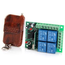
To stop the car during an emergency we need a wireless kill switch which would kill the power to the motors. For the kill switch we will be using a 4 channel remote control from gearbest.com. The module has the following properties:
- Working voltage: DC 12V, relay excitation voltage of 5V
- Static current: Less than 7mA
- Relay output: Controllable AC / DC select-able
- Working frequency: 315MHz, 433.92MHz, can customize special frequency
- Control modes: Latch (L4), Unlatch (M4), Self-latching (T4)
- Channel: 4 channels
- Working range: 200 meters
- High-security, stable performance, low power consumption, and easy to use
The main battery which will power the motors will be having the kill switch in its path, when ever the kill switch is armed main battery will not be fed to the motors.
Software Design
- The Master Controller is responsible for any action the car performs.
- To control the actions of the car, the Master Controller relies upon the periodic scheduler of the FreeRTOS.
- The periodic scheduler ensures that the Sensor, geo-controller messages are read periodically and the actuation command is sent out to the motor controller.
- To read and send messages to the other controllers, the Master Controller makes use of the CAN bus. The controll signal to the motor controller is sent out every 100ms.
- Since the master controller receives a huge number of messages, the Full CAN feature of LPC 1758 is made used. Enabling Full CAN will ensure that the Master Controller will not check for the CAN messages periodically but will directly read a memory location in the RAM which will havr the CAN message.
- For debuggin puposes, the Telemetry module provided by Preet is used. The Telemetry module logs the pre-decided variables in memory and the values of those variables can be read out via the telemetry viewer. This method is better than the printing the values or logging those values in a file as it is realtime and runs in the background.
- Additionally, there are 4 LEDs at the back of the car. The 2 red LEDs light up when ever the car is braking or is stopped. The 2 green LEDs on the either sides of the car blinks when the car is taking a turn. If the car is taking a left turn then the left green LED will blink and vice versa.
- Apart from the LED indications. The Master controller also sends useful debug information to the IO controller to be displayed on the App.
Controller Communication Table
| S.R. | Message Number | Destination | Message Name (MSG_FUNCTION) | Data Layout of Data Sent over CAN (byte[0] = total number of data bytes) |
|---|---|---|---|---|
| 1 | 0x020 | Motor Controller | RESET |
- |
| 2 | 0x220 | Sensor Controller | RESET |
- |
| 3 | 0x221 | Sensor Controller | HEART BEAT |
- |
| 4 | 0x320 | Geo-controller | RESET |
- |
| 5 | 0x420 | Communication Bridge | RESET |
- |
| 6 | 0x021 | Motor Controller | STEERING |
Msg : 2 bits :Direction data |
| 7 | 0x022 | Motor Controller | THROTTLE |
Msg : 1 bit : Increment speed Msg : 2 bits : Custom speed number Msg : 1 bit : Use custom Msg : 1 bit : Forward Msg : 1 bit : stop |
Implementation
The block diagram of the software imlplementation is as follows:
Most of the processing in the master controller took place in the 10Hz task. Some non-critical processing happened at 1Hz and the initialization took place in the period_init task. Below are the detailed screen shot of the different tasks:
The obstruction avoidance algorithm took the messages from the Geo-controller and the sensor controller and turns the car suitably guiding it towards the checkpoint. Below is the detailed flowchart for the same:
Since Full CAN was implemented, the master controller was never required to use any queues or wait for the CAN message to be received.
Testing & Technical Challenges
- Make sure the CAN message IDs for FullCAN is added in the ascending order and this includes the dummy IDs as well.
- Make sure to read the CAN header file thoroughly before implementing FullCAN.
Motor and I/O controller
Group Members
- Sin Yu Ho
- Nimmi Bhatt
Schedule
| Sl.No | Start Date | End Date | Task | Status | Actual Completion date | Problems Encountered |
|---|---|---|---|---|---|---|
| 1 | 9/27/2015 | 10/3/2015 | Decide and purchase rpm sensor and LCD screen module | Completed | 10/1/2015 | |
| 2 | 10/4/2015 | 10/11/2015 | Research and understand servo/throttle motor and issue command from terminal to control it. | Complete | 10/25/2015 | Programming throttle motor backward rotation |
| 3 | 10/11/2015 | 10/18/2015 | Understand LCD module programming and RPM sensor, and create a speed monitoring | Complete | 10/18/2015 | |
| 4 | 10/18/2015 | 10/25/2015 | Design CAN message and implement CAN infrastructure. | Complete | 10/30/2015 | Delay due to full can implementation |
| 5 | 10/25/2015 | 10/30/2015 | Design and create display for monitoring sensor, gps, connection bridge, and master on LCD module | Complete | 11/2/2015 | |
| 6 | 10/31/2015 | 11/13/2015 | Integrate with master, testing and debug | Complete | 11/20/2015 | |
| 7 | 11/14/2015 | 12/10/2015 | Integrate with the whole system, testing and debug | In progress | 12/15/2015 |
Hardware Design
The motor-IO controller consists of four modules: LCD modules, Servo motor module, DC motor module, and speed sensor module. Steering motor module controls steering of the car; DC motor module controls movement; Speed sensor module reports the rpm of a wheel.
- LCD Module: : Generic 20x4 LCD
- Servo motor module: : Arrma ADS-5 Steering Servo motor, which comes with the car
- DC motor module: : Arrma 6 cell 2000mAh 7.2 volt NiMh battery pack, Arrma mega waterproof 35A ESC, and a 15T mega brushed motor, which come with the car
- Speed Sensor module: :Traxxas 6520 RPM Sensor and magnets
Hardware Interface
CAN - Master controller makes decision for motors’ behavior. The decision is sent to motor controller through CAN bus with options that provided by each module. Full can is enabled in motor/IO controller board, which means when the module receives CAN messages, messages are put into ram memory by hardware. Since LCD provides information display screen for each controller on this car, many CAN messages are received. Using normal CAN in this case accumulates the queue in CAN easily and receives messages with the same message id most likely occurs more than once but only the last one matters. Therefore, full can is a better option since the software can read from the ram for the most recent messages. For motor controller, software reads and analyzes motor messages (message ID 0x20, 0x21 and 0x22) every 0.01s, and send 2 messages(message ID 0x100 and 0x102) to CAN bus every 1s. Following DBC file is used to generate CAN messages that is used in motor-io module.
           BO_ 20 RESET_MOTOR: 1 DRIVER
            SG_ RESET_MOTOR_cmd : 0|1@1+ (1,0) [0|0] "" MOTOR
           BO_ 21 STEER: 1 DRIVER
            SG_ DRIVER_STEER_dir : 0|4@1+ (1,0) [0|4] "" MOTOR
           BO_ 22 THROTTLE: 1 DRIVER
            SG_ DRIVER_THROTTLE_stop : 0|1@1+ (1,0) [0|1] "" MOTOR
            SG_ DRIVER_THROTTLE_forward : 1|1@1+ (1,0) [0|1] "" MOTOR
            SG_ DRIVER_THROTTLE_usecustom : 2|1@1+ (1,0) [0|1] "" MOTOR
            SG_ DRIVER_THROTTLE_custom : 3|2@1+ (1,0) [0|3] "" MOTOR
            SG_ DRIVER_THROTTLE_incr : 5|1@1+ (1,0) [0|1] "" MOTOR
           BO_ 100 MOTOR_HEARTBEAT: 8 MOTOR
            SG_ MOTOR_HEARTBEAT_cmd : 0|64@1+ (1,0) [0|0] "" DRIVER
           BO_ 102 SPEED: 1 MOTOR
            SG_ MOTOR_SPEED_speed : 0|8@1+ (1,0) [0|0] "" DRIVER
            SG_ MOTOR_SPEED_rpm : 8|8@1+ (1,0) [0|0] "" DRIVER
PWM (Pulse Width Modulation)- This is an analog signal that micro-controller sends to different module to control the motor speed or a motor rotation. Since we would like to build a self-driving car with a similar performance as its original performance, we used an oscilloscope to measure the base frequency from the wireless receiver, which comes with the car to control the motors. 54.24Hz is measured, and we round it up to 55Hz in the software. Therefore, all the calculation is based on 55Hz in this project.
Software Design
Displaying on LCD
In 1Hz task, LCD will update the display as following.
Speed Sensor
When hall sensor detects a magnetic field difference, an interrupt is generated. This interrupt will increment a counter. In every 0.5s, RPM will be calculated with the counter, and the counter will be cleared.
       void speed_pulse_start(void)
       {
           SpeedMonitor::getInstance()->addRpmCounter();
       }
       SpeedMonitor::SpeedMonitor()
       {
           int port2_5 = 5;
           eint3_enable_port2(port2_5, eint_rising_edge, speed_pulse_start);
           m_rpmCounter = 0;
       }
Setting Steering Direction/ Speed
In 100Hz task, RAM will be checked if steer/throttle CAN message is updated. When a message is received, the PWM to control motor will be updated.
Self Tuning
Based on CAN message from master, custom speed is set. This feature is to make sure the car is running under the custom speed all the time.
Implementation
LCD - LCD is used for displaying sensor data and for debugging and tuning purposes. LCD module communicates to SJSUOne Board via Uart (Uart2 Rx and Tx pins in our case). LCD displays the following information:(See photo in Hardware Design) 1) RPM calculated with the speed sensor and moving direction 2) Right, left, center and back sensor readings 3) Compass Information: Recommended turns and number of check points 4) Distance to destination and check points
| Action | Commands |
|---|---|
| Initialize UART | Uart2::getInstance().init(38400) |
| Sample code for displaying rpm and car action: | sprintf(buffer, "RPM:%d, Act:%s\n", (int)rpm, stop? "Stop": (isForward? "Fwd": "Back")); |
| Add buffer to printStr | printStr.append(buffer); |
| Use printf to output data on UART | Uart2::getInstance().printf(printStr.c_str()); |
| Clear LCD | Uart2::getInstance().putline("$CLR_SCR"); |
Speed Sensor - This sensor detects magnetic field and outputs a pulse to the microcontroller. In this project, five magnets are attached to the wheel. When the wheel rotates, the magnet gets closer to the sensor and the sensor would generate a pulse. With this pulse, software in the microcontroller can calculate time difference between one pulse and another to get the RPM(rotation per minute). The car should maintain in a certain speed selected by the master, and RPM implies the speed. When run speed is lower than selected speed, PWM is increased gradually in order to run with the rpm that master selected.
Servo Motor - For this motor, 10% of duty cycle provides the furthest left rotation, 20% duty cycle provides the furthest right and 15% put the wheel to go straight. Five options are provided according to this data for master controller:
| Options | PWM |
|---|---|
| Far Left | 5.5 |
| Far Left | 6.875 |
| Center | 8.25 |
| Right | 9.625 |
| Far Right | 11 |
ESC (Electronic Speed Controller) - This module receives PWM from microcontroller and outputs a DC signal to DC motor to control speed and rotation direction. To reduce the complexity of the speed control for the master controller, 7 options are provided. 3 levels for moving forward and for moving backward respectively and a stop option. Each level is defined by rpm of a wheel.
| Options | Target Rpm |
|---|---|
| Stop | 0 |
| Forward/Backward Custom 1 | 120 |
| Forward/Backward Custom 2 | 160 |
| Forward/Backward Custom 3 | 200 |
Testing & Technical Challenges
- Backward - We did not know how to control the car goes backward. After quite a bit of research and experiment with the car, we found out that the ESC requires two clicks from the remote to change direction. As a result, we simulates it by sending 2 different close-to-base PWM values.
- Brake - Our car does not have a brake. When the base PWM is sent to the ESC. The car will still move forward due to momentum. Master controller needs to take this into calculation. We will suggest to pick a car with a brake option.
- Speed sensor - At first, we stick 1 magnetic on the right back wheel and target rpm is 120. This also means about 2 pulses per second is received. Since number of data is too little for each second, the analysis/tuning of speed only can happen every 1 second. To increase the number of data, we stick 5 magnetic in total on the wheel, which means about 10 pulse per second. Now, the analysis/tuning of speed will happen every 0.5 second.
- Computer program - One of our teammates' computer, was used to program the flash all the time, all of a sudden, causes the board rebooting after loading the program. We tried to load the exact same hex with another computer to the same board, and the board works fine.
- LCD - We initially planned to use 4D System's 32-PTU LCD. It came with its own GUI interface, called VisieGenie. We faced some problems in getting the GUI to change its value when certain hex codes were sent out on UART. So we decided to go with the simple 20X4 LCD, without a GUI, and display values from sensors early on.
Sensor Controller
Group Members
- Christopher Laurence
- Julio Fuentes
Schedule
| Sl.No | Start Date | End Date | Task | Status | Actual Completion date | Problems Encountered |
|---|---|---|---|---|---|---|
| 1 | 9/27/2015 | 10/3/2015 | Order ultra sonic sensors and read data sheets | Completed | 10/2/2015 | N/A |
| 2 | 10/4/2015 | 10/10/2015 | Connect ultra sonic sensor to LPC board & see if LDAR is an option | Completed | 10/10/2015 | N/A |
| 3 | 10/11/2015 | 10/17/2015 | Read data value from sensor and send in CAN bus | Completed | 10/17/2015 | N/A |
| 4 | 10/18/2015 | 10/24/2015 | Integrate and test proximity sensors | Completed | 10/30/2015 | N/A |
| 5 | 10/25/2015 | 10/31/2015 | Develop battery sensor code | Completed | 10/31/2015 | N/A |
| 6 | 11/01/2015 | 11/07/2015 | Integrate and test battery sensor | Completed | 11/07/2015 | N/A |
| 7 | 11/08/2015 | 11/21/2015 | Complete hardware testing | Completed | 12/12/2015 | N/A |
Hardware Design
For the Sensor team, we decided to use three ultrasonic sensor and a LIDAR sensor for the front. We also use a voltage dividing circuit to bring down the voltage of the batteries, so we can monitor the voltage using two ADC pins. Lastly, our voltage regulator comes with a flag bit that indicates that the voltage has dropped below 5% of 5 volts. Below are the schematics and pin layout for our design.
Hardware Interface
Ultrasonic Sensor
The ultrasonic sensor that we used for this project came with three interface methods. The XL-MaxSonar EZ are a highly senstive sensor that is capable of detecting object up to 725 cm away with a 5V power supply. However, this ultrasonic sensor will not be able to give you the actual distance of an object less than 20 cm away but it will detect it. The sensors allowed reading from ADC, UART, and PWM. The sensor group decided to use PWM because there would not be enough ADC available to do the battery sensor. The UART interface would take approximately 100 ms per a reading but the PWM could read a value between 18ms and 52 ms. Another reason we used PWM was because there are several pins that support PWM available on the SJSU board.The method to use the PWM is to trigger a 20 us high signal to the RX pin and read the value back from the PWM. The PWM will have an rising edge and falling edge and the time held high indicate the distance to the object.
Lidar Lite Laser Distance Sensor
The Lidar laser distance sensor requires 5V and I2C interface operating at a maximum rate of 100Kbps for communication. The Lidar Lite has a maximum acquisition time of 20ms. For reliability, the sampling interval was set to 40ms. The maximum distance measuring capability of the sensor is 60 meters or 196 feet. Testing showed a blind spot of 1-2 inches which was avoided by installing the sensor back a little over two inches.
Battery Sensor
The Battery sensor interface was provided by the 12 bit ADC on the SJ One Board. The ADC has the reference voltage connected to 3.3V and any voltage to be sensed has to be brought down to 3.3V using a resistor divider circuit. The design for the Fury RC car has a 5V source for digital power and a 7.2-7.4 source to power the motor. Both voltages had to be scaled down to 3.3V to interface to the ADC. There are two options to provide a voltage source for the digital circuits. Option 1 was from a NCP59300 LDO Voltage regulator which provides a FLAG output to signal that the 5V wa10% below the nominal 5V. This FLAG signal as well as the reading on the ADC was reported to the master controller. A local LED also provided visual indication that the battery was draining. The second option was to provide the 5V from a USB battery power source which turned out to be the preferred choice since it lasted a long time. Below is a diagram of the power with battery sensing options.
Sensor Controller Pin Mapping
| Pin Name | Function |
|---|---|
| P2_0 | PWM for left Sonic Sensor |
| P2_1 | RX trigger for left Sonic Sensor |
| P2_2 | PWM for right Sonic Sensor |
| P2_3 | RX trigger for right Sonic Sensor |
| P2_4 | PWM for back Sonic Sensor |
| P2_5 | RX trigger for back Sonic Sensor |
| P2_6 | 5V Regulator Flag bit |
| P1_30 | ADC from RC Battery |
| P1_31 | ADC from 5V source for all Boards |
| SDA 2 | LIDAR I2C data |
| SCL 2 | LIDAR I2C clock |
Software Design
For the sensor, we created two tasks to complete the sensor software design. The first task was to initialize the pins for the sonic sensor and create the interrupts for each of the sonic sensors. In the run phase of the task, we trigger the reading pin and use interrupts to get the length in us on the PWM pin. We repeat for each of the three sonic sensors which will have a 45 ms delay between the next triggering of the sonic sensor. The LIDAR is sampled through I2C at the same time as the first sonic sensor it sampled. After all three sonic sensor have data, we applied a simple filter to eliminate bad values. Finally we values from all the sensor are put into a queue that the periodical function will check every 10 Hz and send out a CAN message.
For the Battery sensor was in a separate task that would be sent out everyone 1 Hz. This task initialized the ADC pins and an interrupt for the flag bit from the voltage regulator. In the run phase we read the value of each ADC and place them in a queue with the flag bit value. To get the voltage level of the battery we took the percentage based on the max ADC value and multiple it by the battery's original value. For debug purpose, we had the voltage level displayed on the SJSUOne board.
            BattSen.MotorBattery = ((adc0_get_reading(4)*7.4 * 10) / 4096);
            BattSen.BoardBattery = ((adc0_get_reading(5)* 5 * 10) / 4096);
            BattSen.BatteryFlag = BoardBatteryFlag;
            xQueueSend(battery_data_q, &BattSen, 0);
return true;Implementation
The communication method for the sonic sensors is to use a PWM pin with and interrupt to find the distance. The LIDAR used I2C to send a 16 bit distance value and the battery sensor used ADC. To communicate with the other boards, we used the below CAN messages. Below is each of the CAN messages in DBC format.
BO_ 140 HEARTBEAT: 1 SENSOR
 SG_ DRIVER_HEARTBEAT_cmd : 0|8@1+ (1,0) [0|0] "" DRIVER
BO_ 142 SONARS: 8 SENSOR
 SG_ SENSOR_SONARS_left : 0|16@1+ (1,0) [0|0] "" DRIVER,IO
 SG_ SENSOR_LIDAR_middle : 16|16@1+ (1,0) [0|0] "" DRIVER,IO
 SG_ SENSOR_SONARS_right : 32|16@1+ (1,0) [0|0] "" DRIVER,IO
 SG_ SENSOR_SONARS_rear : 48|16@1+ (1,0) [0|0] "" DRIVER,IO
BO_ 144 BATTERY: 3 SENSOR
 SG_ SENSORS_Motor_BATTERY : 0|8@1+ (1,0) [0|0] "" DRIVER, IO
 SG_ SENSORS_Board_BATTERY : 8|8@1+ (1,0) [0|0] "" DRIVER, IO
 SG_ SENSORS_Flag_BATTERY : 16|8@1+ (1,0) [0|0] "" DRIVER, IO
| Sr. No. | Message Number | Destination | Message Name (MSG_FUNCTION) | Data Layout of Data Sent over CAN (byte[0] = total number of data bytes) |
|---|---|---|---|---|
| 1 | 0x140 | Master | HEARTBEAT |
- |
| 2 | 0x142 | Master | SONIC SENSOR DATA |
Msg : byte[0:1] : (uint16_t) middle (LIDAR) Msg : byte[0:1] : (uint16_t) left Msg : byte[2:3] : (uint16_t) right Msg : byte[4:5] : (uint16_t) back |
| 3 | 0x144 | Master & I/O Controller | BATTERY DATA |
Msg : byte[0] : (uint8_t) Motor battery * 10 Msg : byte[1] : (uint8_t) Board battery * 10 Msg : byte[2] : (uint8_t) Board battery Flag |
Testing & Technical Challenges
- For the sonic sensor the biggest challenge was preventing the sensor from interfering with each other. While testing the sensor would get incorrect values if the time between triggering was too short. I notice with a 30 ms delay that the sensor seemed to be working correctly but when an object was placed on the right side of the car the left sensor would react. By placing a delay of 45 ms I was able to only see the right sensor react and the left remain the same.
- The next issue during testing was getting value from the sensor that were greater than the device was capable of having. By applying a simple filter to weed out bad value allows the master only to receive good values.
- During the last stages of testing, we notice that the sensors were receiving low value because it was picking up the ground. To fix the issue we raised the sensors 3 inches and slightly angled them back to increase the range.
- The Lidar sensor sends a value of 0 when it is out of range. Also, it sends 0 if an object is very close like 1 inch away. To solve this problem, the Lidar sensor was moved back so that it will never read 0 for an object that was too close. For the out of range case, the 0 value was replaced with 600.
Geographical Controller and Compass
Group Members
Schedule
| Sl.No | Start Date | End Date | Task | Status | Actual Completion date | Problems Encountered |
|---|---|---|---|---|---|---|
| 1 | 9/23/2015 | 10/2/2015 | Researched and decided upon the GPS module and Compass module. | Completed | 10/1/2015 | None |
| 2 | 10/3/2015 | 10/3/2015 | Ordered GPS module and compass module. | Completed | 10/2/2015 | None |
| 3 | 10/5/2015 | 10/14/2015 | Interface GPS module and
compass module to SJOne board. |
Completed | 10/20/2015 | The delivery of GPS and compass module was delayed. |
| 4 | 10/15/2015 | 10/25/2015 | Parse GPS data and format the data to be transmitted
Test code to get compass reading information |
Completed | 10/25/2015 | None |
| 5 | 10/26/2015 | 10/30/2015 | Calibrating the compass module.
Integration of GPS and compass module. Interfacing of GPS and compass module to Android. |
Completed | 11/25/2015 | Testing of the module is taking time.
Burnt GPS module, had to order another one. |
| 7 | 11/1/2015 | 11/13/2015 | Integration with Master through CAN bus. | Completed | 12/05/2015 | Had to filter the data |
| 8 | 11/15/2015 | 12/10/2015 | Testing and calibrating with other modules. | Completed | 12/16/2015 | Tuning |
Hardware Design
GPS Module
GPS module used in our project is Sparkfun Venus GPS - (Model: GPS-11058) and embedded antenna from Sparkfun - (Model: GPS-00177). We were able to configure this module at 10Hz and communicate at 38400bps through UART. Skytraq has developed a Graphical User Interface to check Latitude, Longitude and every possible information this GPS module provides. GPS can also be configured to operate and communicate at various speed though the provided Graphical User Interface. This module has got an on-board flash to store these configuration. There are three modes in which this module can operate,
1. Cold start: Cold Start is performed every time when the GPS module is turned off without backup power supply connected. It is the longest starting time out of the three. It usually took around 15 to 20 minutes to get a GPS fix indoors.
2. Hot start: GPS module will perform Hot Start if the GPS module is provided with backup power and is powered on any time within the 2-hour time frame after GPS was previously turned off, the required fix is still stored inside the its flash memory and will not be changed. The Hot start time is typically around 10 to 15 seconds.
3. Warm start: Warm Start is performed if the module is switched on after the 2-hours of time, since satellite data has to be refreshed. Warm start time is typically around 2 to 3 minutes.
Compass Module
Compass module used for our project is CMPS 11 by Devantech Ltd(Robot Electronics). It is tilt compensated module which made life easier for us. There are two ways to establish communication between CMPS 11 and SJ-ONE board. UART and I2C are the two ways and we choose to do use I2C for communication. Since, it is faster.
1. First thing to do before calibrating the compass module is to make sure that there is proper I2C communication established between the compass module and SJ-ONE board. Once we have communication setup we can got ahead and find out the bearing degree of the compass and verify it with an actual analog compass.
2. Once the communication is setup and working as desired, then we can calibrate the compass. Calibration is done by sending 3 commands for every 20ms. The purpose of calibration is to remove sensor gain and offset of both magnetometer and accelerometer and achieves this by looking for maximum sensor outputs.
Hardware Interface
GPS module
Communication between GPS and SJOne board is through UART2. GPS was configured to communicate at 38400bps and operate at 10Hz. A coin battery of 3.3V was connected between Vbat and Gnd of GPS. The coin battery helped in hot start of GPS module.
Compass module
CMPS 11 module provides two ways of communication. First option is I2C and second option is UART. We chose I2C communication since it is faster when compared to UART. Since GPS uses UART2 and Seven segment display uses UART3 we decided to use I2C. The operating voltage range is from 3.3v to 5v.
7 segment display
UART3 is used to send out commands to 7 segment display. This is used to display the team name and the checkpoint number.
Overview of Geo Controller design
Software Design
GPS module
A task is created to read the GPS values from the module. This task starts reading GPS coordinates when there is some data on UART, the received data is then checked if it is valid. If valid, then the data is pushed onto queue which is basically every 200ms, since the GPS module is configured to work at 5Hz. GPS module transmits data in NMEA format and we are following the $GPRMC data. GPS module was configured for pedestrian mode. Module was configured through the software provided by skytraq. Coordinates from communication module is received at the start of code which contains checkpoint details. The GPS data and the checkpoint data is used to calculate the distance to next checkpoint, distance to final destination and angle in which the car has to head by using Haversine formula. Once a checkpoint is reached, the checkpoint is updated and continues till final destination is reached. Once the final destination is reached, master is informed about the same. Present GPS data is transmitted back to communication bridge.
Compass module
All of compass calculation is done in 10Hz periodic task. Initial bearing is calculated and compared with the desired heading. The desired heading is calculated using the longitude and latitude values provided by the GPS module. Based on this value a turn decision is made and sent to the master to handle it.
- For entering into the calibration mode, switch 1 on SJ- One board has to be pressed.
- Switch 2 to come out of calibration mode back to heading mode.
- Switch 3 to do the factory reset setting.
Calibration of Compass module
- Purpose of calibration is to remove sensor gain and offset of both magnetometer and accelerometer.
- This is achieved by looking for maximum sensor outputs.
- To enter into calibration mode, we need to send 3 byte sequences 0xF0,0xF5 & 0xF6 to the command register.
- There must be a minimum of 20ms delay between each I2C frame.
Algorithm to calculate distance using longitude and latitude values.
- The distance is calculated between 2 geographical points.
- It is used to calculate to distance between two checkpoints in our project.
- We use ‘haversine’ to calculate the distance of two points over a sphere i.e the earths surface.
Haversine formula: a = sin²(Δφ/2) + cos φ1 ⋅ cos φ2 ⋅ sin²(Δλ/2) c = 2 ⋅ atan2( √a, √(1−a) ) d = R ⋅ c
where φ is latitude, λ is longitude, R is earth’s radius (mean radius = 6,371km) (assuming earth to be a sphere and ignoring ellipsoidal effects)
Algorithm to calculate desired heading using longitude and latitude values.
- This algorithm is used to calculate the desired heading direction between two geographical locations. This helps in navigating car to reach the destination.
- The algorithm calculates the heading between present checkpoint and the next checkpoint by taking the present latitude and longitude values and the next checkpoint's latitude and longitude values.
- The final heading direction may change when we travel towards the destination because of the shape of earth. Hence, the forward azimuth formula is used to calculate the initial direction.
- To get the final direction, take bearing from the end point to the start point and reverse it as follows, θ = (θ+180) % 360
Formula: θ = atan2( sin Δλ ⋅ cos φ2 , cos φ1 ⋅ sin φ2 − sin φ1 ⋅ cos φ2 ⋅ cos Δλ )
where φ is latitude, λ is longitude
Since this formula generates a negative value (-180 to 180), we need to normalize the value to get a compass bearing (0 - 360). We have divided the compass into 12 zones of 30 degrees each. This allows the car to remain in one zone and only turn if a heading / turn of more than 30 degrees is to be performed. This provides stability to the car thereby avoiding heading correction every time the algorithm computes a heading.
- The circle is divided into 12 zones (360/30 = 12).
- If the desired heading is greater than 30 degree then a decision is made to turn right.
- If the desired heading is greater than 90 degree then a decision is made to take a U - turn.
- If the angle is between 330 degrees to 0 degrees and from 0 degrees to 30 degrees then car heads straight.
- Only if the desired heading is not in between these ranges then a decision is made to turn the car.
Controller Communication Table
DBC file, used to generate structures that can be used in the code. Since we had already implemented with our own structures, we did not use DBC for our project.
BO_ 160 HEARTBEAT: 0 GEO
SG_ GEO_HEARTBEAT_cmd : 0|0@1+ (1,0) [0|0] "" DRIVER
BO_ 162 HEADING: 6 GEO
SG_ GEO_HEADING_turnangle : 0|8@1+ (1,0) [0|0] "" MASTER, IO
SG_ GEO_HEADING_checkpoint : 8|7@1+ (1,0) [0|0] "" MASTER, IO
SG_ GEO_HEADING_isfinal : 15|1@1+ (1,0) [0|0] "" MASTER, IO
SG_ GEO_HEADING_distancetofinaldestination : 16|16@1+ (1,0) [0|0] "" MASTER, IO
SG_ GEO_HEADING_distancetonextcheckpoint : 32|16@1+ (1,0) [0|0] "" MASTER, IO
BO_ 461 LOCATION: 8 GEO
SG_ GEO_LOCATION_latitudeDecimal : 0|8@1+ (1,0) [0|0] "" COMMUNICATIONBRIDGE, IO
SG_ GEO_LOCATION_latitudeFloat : 8|20@1+ (1,0) [0|0] "" COMMUNICATIONBRIDGE, IO
SG_ GEO_LOCATION_longitudeDecimal : 28|8@1+ (1,0) [0|0] "" COMMUNICATIONBRIDGE, IO
SG_ GEO_LOCATION_longitudeFloat : 36|20@1+ (1,0) [0|0] "" COMMUNICATIONBRIDGE, IO
SG_ GEO_LOCATION_checkpoint : 56|7@1+ (1,0) [0|0] "" COMMUNICATIONBRIDGE, IO
SG_ GEO_LOCATION_isFinal : 63|1@1+ (1,0) [0|0] "" COMMUNICATIONBRIDGE, IO
BO_ 47F ACK: 0 GEO
SG_ GEO_ACK_cmd : 0|0@1+ (1,0) [0|0] "" COMMUNICATIONBRIDGE
| Sr. No. | Message Number | Destination | Message Name (MSG_FUNCTION) | Data Layout of Data Sent over CAN (byte[0] = total number of data bytes) |
|---|---|---|---|---|
| 1 | 0x160 | Master | HEARTBEAT |
- |
| 2 | 0x162 | Master and I/O | COMPASS HEADING DATA |
Msg : 8 bits : turn angle Msg : 7 bits : checkpoint Msg : 1 bit : isFinal Msg : 16 bits : distance to final destination Msg : 16 bits : distance to next checkpoint |
| 3 | 0x461 | Communication Bridge and I/O | GPS DATA |
Msg : 8 bits : latitude_decimal_part Msg : 20 bits : latitude_float_part Msg : 8 bits : longitude_decimal_part Msg : 20 bits : longitude_decimal_part Msg : 7 bits : checkpoint Msg : 1 bit : isFinal |
| 4 | 0x47F | Communication Bridge | CHECKPOINT RECEIVED |
- |
Testing & Technical Challenges
For Debug purpose:
On board LED 3 is toggled every time there is an error to push the data onto queue.
On board LED 4 is toggled every time the data is not read from gps.
Different numbers were displayed on the 7 segment display of SJOne board to debug the compass modes.
FURY was displayed on 7 segment display of SJOne board on a rolling basis to indicate the destination was reached.
Testing Procedure
- The checkpoints were added once, manually at the start of the code. The checkpoint data was collected from the android app at different locations.
- Distance calculations(next checkpoint distance and final distance) were tested by using these test values of latitude and longitude.
- Desired heading angle was also calculated on similar lines.
- GPS was carried along with the SJOne board to these checkpoints and was checked for the update of checkpoint data in software.
- Compass heading angle and desired angle was also mapped similarly.
- SJOne board was connected to CAN bus and was checked if the messages were sent through CAN bus by using a CAN analyzer tool from microchip.
Challenges:
- Initial fix for GPS used to take a lot of time. At first, it took around 1 hour and 30 minutes to get a fix. Then understood that GPS wont fix to a satellite if it is in a closed environment. Then tried to get a fix outside and it took around 30 minutes which is better but still not good. After reading a lot about the working of hot start mode in GPS module, we figured out that Vbat of around 3V has to be connected. This improved the time to get a satellite fix and it reduced to around less than 2 minutes.
- When the car was carried around the update of GPS was correct and car worked as desired, the problem was when the car was let lose on road. The car never used to go straight. To avoid this, kalman filter was implemented and then tested. There was no much changes since IMU was not used and many other factors was not considered to factor in kalman filter. The GPS was then slowed down by configuring it to update at 5Hz, this stabilized the car. The figures provide the movement of car with GPS update rate of 5Hz and 10Hz.
- Don't use 5v supply because for us it somehow created more than expected offset and our initial testing failed because of it. Later we switched back to 3.3v and offset was in expected range and testing went well too.
- If any objects such as laptop or mobile was taken near compass, the calibration would be lost and compass had to be re-calibrated. Since there was no software calibration available on the board, we had to manually remove the compass from the car, send calibration commands and then calibrate it. After few days, we tried factory reset commands which brought back the compass to correct readings, this was integrated in our code to reset the compass through android app by send messages through CAN bus. This reduced a lot of work for us.
Android & Communication Bridge Controller
Group Members
- Chinmayi Divakara
- Praveen Prabhakaran
Schedule
| Sl.No | Start Date | End Date | Task | Status | Actual Completion date | Problems Encountered |
|---|---|---|---|---|---|---|
| 1 | 9/30/2015 | 9/30/2015 | Decide and purchase Bluetooth Module | Completed | 9/30/2015 | None |
| 2 | 9/30/2015 | 10/14/2015 | Develop Basic Android App with Bluetooth Sensor Communication | Completed | 10/14/2015 | |
| 3 | 10/15/2015 | 10/20/2015 | Interface Bluetooth Module with SJSU Dev Board | Completed | ||
| 4 | 10/12/2015 | 10/26/2015 | Be able to send bi-directional arbitrary messages between Android App and Dev Board via Bluetooth | Completed | ||
| 5 | 10/14/2015 | 11/21/2015 | Interface Bluetooth Module with CAN | |||
| 6 | 10/26/2015 | 11/30/2015 | Integration with GPS module testing and fine tuning. | |||
| 7 | 11/01/2015 | 11/13/2015 | Integration with Master through CAN bus | |||
| 8 | 11/15/2015 | 12/10/2015 | Android App GUI enhancements (Google Maps, Google Drive) |
Hardware Design
- For wireless communication between the SJSU One Board and a Android device, a Bluetooth (RN-421) module is used. This module was chosen because it can connect and mount directly onto the SJSU One Board's XBee breakout socket.
- To give a longer range communication, we used wireless mesh network (Nordic) which was available in SJOne board.
1. Bluetooth Module (RN-421):
Features:
- Fully qualified Bluetooth version 2.1 module, support version 2.1+Enhanced Data Rate (EDR)
- Backwards compatible with Bluetooth version 2.0, 1.2 and 1.1.
- Low power (26uA sleep, 3mA connected, 30mA transmit)
- UART (SPP or HCL) and USB (HCI only) data connection interfaces.
- Sustained SPP data rates: 240 Kbps (slave), 300Kbps (master).
- HCI data rates: 1.5 Mbps sustained, 2.0Mbps burst in HCI mode.
- Bluetooth SIG certified.
- Castellated SMT pads for easy and reliable PCB mounting.
- Certifications: FCC, ICS, CE
2. Nordic Wireless:
Features:
- Worldwide 2.4GHz ISM band operation.
- Common RX and TX interface.
- Low power 1.9 to 3.6V supply range.
- 250kbps, 1 and 2Mbps air data rate.
- 1 to 32 bytes dynamic payload length.
- 3 separate 32 bytes TX and RX FIFOs
Hardware Interface
Bridge between Nodic wireless and bluetooth:
Communication between Android Application and the Communication bridge is through Bluetooth. In order to increase the range and to give a stable uninterrupted communication, we further split the communication bridge. One Node (SJone board) receives the data via Bluetooth-uart interface, which processes the command sent gets the data parses it and reroutes the data to CAN Node via Nordic wireless. The data from the received wireless packets is sent over CAN bus with appropriate message IDs.
Software Design
Git
Since Communication Bridge module contains both Android App and LPC1758_FreeRTOS project, we created following folder structure.
- LPC1758_freertos
- Android- Android Project
- LPC1758_Communication_Bridge- which contained the freertos project for LPC1758
Implementation
Implementation for this module consists the development of :
1. Android App
2. CAN-Bluetooth communication bridge
Below is the System Sequence Diagram:
Android App
Android App using Java and android application framework(API 22). The map activity is implemented with the integration of google map. Bluetooth connectivity is realized with the help of Bluetooth API's provided alongside the framework for the RF communication. For asynchronous message passing within the application,handler package is used.To access the checkpoints we are using Google direction API and JSON parser to parse the data received.
| S.R. | Command | Code |
|---|---|---|
| 1 | Start | start$ |
| 2 | Checkpoints | check <Lattitude> <Longitude> <Checkpoint Number> <IsFinal>$ |
CAN-Bluetooth communication bridge
Interface consists of two wireless nodes. One node, gets the input commands from the Android App via Bluetooth, processes the received command and data, to relay it over Nordic wireless mesh network. Second Node receives the wireless packets, gets the data and sends it to the GPS module over can bus. Similarly, The CAN node taps the CAN messages for compass , GPS Location and distance and keeps transmitting the data back to Android App over the same network. The detailed sequence diagram is given below. As the code for the both the nodes in the communication bridge is in the same source, we used a macro to switch between them. When the NODE_BLUETOOTH is 1, the bluetooth .hex file is flashed. Similarly when the NODE_CAN is 1, the respective .hex file is flashed.
When data is sent over Bluetooth to Android App it follows the format as given in the table below. Here the '~' is given a delimiter to mark the end of the command.
| S.R. | Command | Code |
|---|---|---|
| 1 | Acknowledgement | a~ |
| 2 | Location Values from Car | l<Lattitude> <Longitude>~ |
| 3 | Compass Values from Car | c<Heading Angle> <Desired Angle> <Turn Direction>~ |
| 4 | Distance Values from Car | d<Next Checkpoint Distance> <Final Distance >~ |
Communication Bridge CAN message
To communicate with the other boards, we used the below CAN messages. Below is each of the CAN messages in DBC format.
BO_ 180 HEARTBEAT: 1 CommunicationBridge
SG_ CommunicationBridge_HEARTBEAT_cmd : 0|8@1+ (1,0) [0|0] "" DRIVER
BO_ 181 Drive_Mode: 1 CommunicationBridge
SG_ CommunicationBridge_DriveMode_cmd : 0|8@1+ (1,0) [0|0] "" DRIVER
BO_ 182 STOP: 1 CommunicationBridge
SG_ CommunicationBridge_STOP_cmd : 0|8@1+ (1,0) [0|0] "" DRIVER
BO_ 382 LOCATION: 8 CommunicationBridge
SG_ CommunicationBridge_LOCATION_latitudeDecimal : 0|8@1+ (1,0) [0|0] "" GEO
SG_ CommunicationBridge_LOCATION_latitudeFloat : 8|20@1+ (1,0) [0|0] "" GEO
SG_ CommunicationBridge_LOCATION_longitudeDecimal : 28|8@1+ (1,0) [0|0] "" GEO
SG_ CommunicationBridge_LOCATION_longitudeFloat : 36|20@1+ (1,0) [0|0] "" GEO
SG_ CommunicationBridge_LOCATION_checkpoint : 56|7@1+ (1,0) [0|0] "" GEO
SG_ CommunicationBridge_LOCATION_isFinal : 63|1@1+ (1,0) [0|0] "" GEO
BO_ 385 STOP: 1 CommunicationBridge
SG_ CommunicationBridge_CompassFactoryReset_cmd : 0|8@1+ (1,0) [0|0] "" GEO
| S.R. | Message Number | Destination | Message Name (MSG_FUNCTION) | Data Layout of Data Sent over CAN (byte[0] = total number of data bytes) |
|---|---|---|---|---|
| 1 | 0X180 | Master | HEARTBEAT |
No DATA |
| 2 | 0X181 | Master | DRIVE MODE |
No DATA |
| 3 | 0X182 | Master | STOP |
No DATA |
| 4 | 0x382 | Master | LOCATION POINTS |
Msg : 8 bits : latitude_decimal_part Msg : 20 bits : latitude_float_part Msg : 8 bits : longitude_decimal_part Msg : 20 bits : longitude_decimal_part Msg : 7 bits : checkpoint Msg : 1 bit : isFinal |
| 5 | 0X385 | Master | Compass Factory Reset (Debug) |
No DATA |
Andriod Application Features
The Android App sends the destination & intermediate checkpoints to the car. It also receives the initial co-ordinates of the car and its further location coordinates as it navigates towards the destination. The intermediate checkpoints is got via Google direction API. The App Interface consists of a Bluetooth connect button - which connects to the Bluetooth module, Send button - which sends all the checkpoint data, Start button - to set the car in drive mode. Reset button - resets the map and marks the 'now' location of the car. GPS button- Shows the co-ordinates data, heading angle, desired angle, distance to next checkpoint, distance to final checkpoint, and turn direction.
Following are the screen shots for the features implemented:
Testing & Technical Challenges
- Using the existing terminal task present in the FreeRTOS project – Initially we used the existing terminal task to process the command sent from the from the app to the Bluetooth module interfaced through Uart. Terminal Task was hooked to Uart0, and this was changed to Uart2. Doing this resulted in removal of existing terminal based debugging and also there was no return communication back to the android app. Hence, we used Uart2 Tx task to process the incoming commands.
- Getting Initial location from GPS on Android phone – Doing this created a lot of offset from the location that was obtained to the actual location of the car. Therefore we tapped the CAN messages sent out by GPS module on the car to be sent out to the android App. The messages were tapped continuously at a frequency of 1Hz to display on the App. This gave a trace of the cars location on the App, and was used to debug and restart the GPS module on the car whenever there was discrepancy in the location co-ordinates obtained from the GPS module and explained the behavior of the car at times.
- Expanding the range and stabilizing communication between App and Car – Since we used a two way communication between the App and car, we faced two problems 1) range of the bluetooth connection from App to car was short, so when the car is in motion there was dis-connectivity in the communication channel, resulting in manual re-connection every time. Solution to this was to use another wireless channel which gives a stable, long range channel for communication. We used two nodes, one which communicates with Android App via Bluetooth and the other node is the CAN node on the car. The two nodes were connected by a wireless channel through the existing on board Nordic wireless module and Nordic mesh stack. Doing this there was only a loss in wireless packets but never a dis-connectivity in the communication channel.
- For the purpose of testing we used bluetooth node as follows:
- Kill Switch(Switch 4): When the kill switch is pressed a message is sent to the master to reset all the other boards. This was helpful during the testing when collisions or unanticipated events occurred.
- Start Switch(Switch 2): Using the start switch the car can be started without giving any location. This was useful when testing indoors as location was not available.
- Compass Factory Reset switch(Switch 1): This switch was used to perform a factory reset for the compass. During calibration of the compass this switch was extensively used.
Integration
Testing & Technical Challenges
Issue 1:
Full CAN was implemented to receive the required data. During CAN communication, when a particular message intended to receive for one particular module was received, the SJOne board of that module used to get stuck, there was no watchdog timer reset as well.
Solution - The Full CAN messages had to be added in ascending order. Once this was implemented, the working was smooth.
Issue 2:
The car used to turn even if the destination was straight ahead. There was a bit of difficulty to debug this issue. We could not figure out if it was due to GPS, compass or sensors. The front left and right sensors were mounted a bit low on the car and the readings from the sensors were low, due to reflections from ground, and hence there was difficulty in tuning threshold levels for obstacle avoidance.
Solution - The sensors were mounted a bit higher and was tilted backwards which gave a good range. The issue was debugged through LCD display and android app. All the important values were displayed on LCD and the android app provided better visualization of the GPS position.
Conclusion
A self-driving car was successfully designed,implemented and tested.The design was changed multiple times during the course of the project. While the final product is not perfect, autonomous navigation of the car has been achieved. If some more time was available , we would have improved the car navigation and added more features. Given a single destination, or multiple checkpoints, the car can successfully navigate to the final destination avoiding all obstacles in its path.
This project was a great learning experience since it covered all aspects of a product design: mechanical design and assembly, procurement of parts, software design, coding and testing, and team work.
Word of advice:
- Invest time in debugging tools and options, it will save a lot of time while testing.
- Use Telemetry to check variable values than printf statement.
- Use LCD to display all important messages/values.
- Try to develop an android device such that all the messages are update on the app, it will be handy to check the updated values and for debugging.
- Start testing early to figure out the problems and tune your car for better results.
- CAN analyzer was a great tool to check the CAN messages on CAN bus. This helped in resolving on which board the problem resided.
Project Video
To watch our project video, click here
Project Source Code
References
- Preetpal Kang's lecture notes of CMPE 243, Computer Engineering, San Jose State University, Aug-Dec 2015.
- Fall 2014 Wiki Projects
- CAN Transceiver
- Adafruit Ultimate GPS Breakout - 66 channel w/10 Hz updates - Version 3
- GPS data calculation accuracy
- GPS Longitude Latitude distance calculator
- Calculate distance between two points
- HCSR04 Ultrasonic Sensor
- Android Developers manual
- Learning Git Tutorials
Acknowledgement
We would like to thank our instructor Preet for always inspiring, encouraging and guiding us to learn and build cool projects related to embedded systems. We really appreciate his patience. This was our first exposure to CAN bus communication and we learned a lot about it. We would also like to thank all our team members for helping each other out while working on this project. Special thanks to Julio Fuentes for designing the hardware frame.
Appendix
- Laser Distance Sensor File:F15 243 Fury Lidar spec.pdf
- Sonic Sensor File:CmpE243 F15 Fury XL-MaxSonar-EZ Datasheet.pdf
