Difference between revisions of "F12: Android Controlled MP3"
Anthony f12 (talk | contribs) (→Implementation) |
Anthony f12 (talk | contribs) (→Testing & Technical Challenges) |
||
| Line 326: | Line 326: | ||
A technical challenge was understanding how to connect the WiFly module to a network. Once the UART driver was created and tested, we wanted to set up the WiFly module to our home network. The instructions from the user manual is incomplete and incorrect, therefore it was difficult to set up. The user manual doesn’t document any steps to set up the WiFly module and isn’t organized well. It lists all the commands, but does not inform which commands are necessary to connect to a network. The problem was also not creating a good UART user interface to set up the WiFly module. After creating a good UART user interface and having an example to follow, the WiFly module was simpler to set up. | A technical challenge was understanding how to connect the WiFly module to a network. Once the UART driver was created and tested, we wanted to set up the WiFly module to our home network. The instructions from the user manual is incomplete and incorrect, therefore it was difficult to set up. The user manual doesn’t document any steps to set up the WiFly module and isn’t organized well. It lists all the commands, but does not inform which commands are necessary to connect to a network. The problem was also not creating a good UART user interface to set up the WiFly module. After creating a good UART user interface and having an example to follow, the WiFly module was simpler to set up. | ||
| + | ===Testing the WiFly Module=== | ||
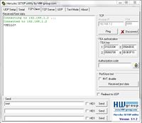
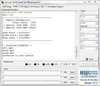
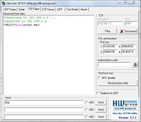
To test if the WiFly module was connected to the network, we first edit the correct parameters. Then we used Hercules to connect to the WiFly module. If Hercules connects, then the WiFly module will send *Hello* to the device and *OPEN* through UART. The LPC2148 was set to receive data from UART1 and echo the results through UART0 to Hercules via serial. Hercules’ TCP Client was used to connect to the WiFly module and it would receive data through TCP. The test results can be seen below. | To test if the WiFly module was connected to the network, we first edit the correct parameters. Then we used Hercules to connect to the WiFly module. If Hercules connects, then the WiFly module will send *Hello* to the device and *OPEN* through UART. The LPC2148 was set to receive data from UART1 and echo the results through UART0 to Hercules via serial. Hercules’ TCP Client was used to connect to the WiFly module and it would receive data through TCP. The test results can be seen below. | ||
| − | [[File:CmpE146_F12_T4_TCP_Client_Open_Connection.jpg|200px|thumb|center|TCP Client establishing connection with WiFly module]] | + | [[File:CmpE146_F12_T4_TCP_Client_Open_Connection.jpg|200px|thumb|center|Figure 5. TCP Client establishing connection with WiFly module]] |
| − | [[File:CmpE146_F12_T4_UART1_Connection_Established.jpg|200px|thumb|center|LPC2148 receiving confirmation from WiFly module]] | + | [[File:CmpE146_F12_T4_UART1_Connection_Established.jpg|200px|thumb|center|Figure 6. LPC2148 receiving confirmation from WiFly module]] |
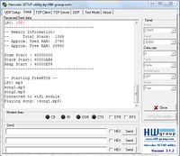
Once the connection was tested, we can move on to test if the LPC2148 can receive commands and perform the appropriate actions. Hercules’ TCP Client can still be used because it can also send data. The TCP Client was used to send command to the WiFly module which will be echo to the LPC2148 via UART. The result can be seen below. | Once the connection was tested, we can move on to test if the LPC2148 can receive commands and perform the appropriate actions. Hercules’ TCP Client can still be used because it can also send data. The TCP Client was used to send command to the WiFly module which will be echo to the LPC2148 via UART. The result can be seen below. | ||
| − | [[File:CmpE146_F12_T4_TCP_Client_Send_Commands.jpg|200px|thumb|center|TCP Client sending commands to WiFly module]] | + | [[File:CmpE146_F12_T4_TCP_Client_Send_Commands.jpg|200px|thumb|center|Figure 7. TCP Client sending commands to WiFly module]] |
| + | |||
| + | [[File:CmpE146_F12_T4_UART1_Receive_Commands.jpg|200px|thumb|center|Figure 8. LPC2148 responding to commands from WiFly module]] | ||
| + | |||
| + | ===Testing the Android Application=== | ||
| + | The android application was tested using Hercules' TCP server. Since the android application will act as a TCP client, we set up Hercules as the TCP server. The first thing that needed to be done for the connection to be made is making sure the android device and the computer is connected to the same network. The IP address of the computer running Hercules need to be obtained. Once Hercules is set up to listen for clients, the android application can be set up. Once the IP address and port number are entered into the android device and the connect button is pressed, the TCP connection will be established. The buttons on the android device were pressed to see if the correct command is sent to the Hercules' server and data was sent from the server to see if the android device would receive the data. After performing the test, the android application was verified to send the correct command mapped to each button and successfully receive and display the data sent from the server. Figure 9. shows the Hercules' TCP server receiving data from and sending data to the android application. Figure 10 shows the android application with the received data displayed. | ||
| + | |||
| + | [[File:CmpE146_F12_T4_Hercules_Sending_and_Receiving.jpg|thumb|center|Figure 9. Hercules receiving from and sending to android application ]] | ||
| + | |||
| + | [[File:CmpE146_F12_T4_Android_App_Receiving.jpg|thumb|center|Figure 10. Android application receiving from Hercules]] | ||
| − | |||
Include sub-sections that list out a problem and solution, such as: | Include sub-sections that list out a problem and solution, such as: | ||
Revision as of 07:05, 9 December 2012
Contents
Wirelessly Control a MP3 Player
Abstract
Using an Android program to wirelessly control a MP3 Player. The Android program will contain functions to command the operation of the MP3 player. The user can press a button to play a song or change the volume.
Introduction & Features
- An android application with MP3 functions
- Wirelessly control the MP3 player using the android application
- MP3 features: play, pause, resume, stop, fast forward, volume control, etc.
Team Members and Responsibilities
- Anthony Hu
- Android application that allows communication with MP3 board using TCP
- Ricky Nguyen
- Implement wifi module with MP3 board by interfacing UART driver
Schedule
Show a simple table or figures that show your scheduled as planned before you started working on the project. Then in another table column, write down the actual schedule so that readers can see the planned vs. actual goals. The point of the schedule is for readers to assess how to pace themselves if they are doing a similar project.
| Week | Planned Tasks | Status |
|---|---|---|
| 1 |
|
|
| 2 |
|
|
| 3 |
|
|
| 4 |
|
|
| 5 |
|
|
| 6 |
|
|
Parts List & Cost
Give a simple list of the cost of your project broken down by components. Do not write long stories here.
| Parts | Cost |
|---|---|
|
LPC2148 Microcontroller |
$60 |
|
RN-XV WiFly Module |
$35 |
|
Netgear N300 Wireless Router |
$45 |
Design & Implementation
The design section can go over your hardware and software design. Organize this section using sub-sections that go over your design and implementation.
Hardware Design
Discuss your hardware design here. Show detailed schematics, and the interface here.
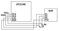
To power the wifi module, it requires an average 3.3V to operate and can take a maximum voltage of 3.7V and a minimum voltage of 3.0V. The power pin from the LPC2148 supply a steady 3.3V and can be used to power the wifi module. The wifi module can be connected to the LPC2148 through UART. This requires two pin from both component, Tx and Rx. The following table shows the pin descriptions and the following figure shows the pin connections.
| LPC | Wifi |
|---|---|
|
P0.8 (TXD1) |
P3 (UART_RX) |
|
P0.9 (RXD1) |
P2 (UART_TX) |
|
3.3V Pin |
P1 (VDD_3V3) |
|
GND Pin |
P10 (GND) |
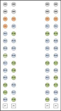
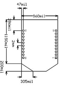
The following figures show the pin configuration of the LPC2148 and RN-XV WiFly Module, respectively.
Hardware Interface
In this section, you can describe how your hardware communicates, such as which BUSes used. You can discuss your driver implementation here, such that the Software Design section is isolated to talk about high level workings rather than inner working of your project.
The hardware involved in this project are the LPC2148 microcontroller, RN-XV WiFly Module, SD Card, MP3 Decoder, and DAC. The LPC2148 is connected to the SD Card through SPI and connectd to MP3 Decoder and DAC through I2C. In previous lab assignments, the drivers for SPI and I2C were created for these connections. The MP3 project was extended to include wireless communication to an Android Device. Wireless communication is established by interfacing the LPC2148 to the RN-XV WiFly Module through UART. LPC2148 have two UART port and UART0 is already used. Therefore, the WiFly module is connected through UART1. To use UART1, a driver must be created for it. The UART1 driver was created base off the UART0 driver. Minor changes were made to address UART1 registers. The figure below shows the buses being used.
Software Design
Show your software design. For example, if you are designing an MP3 Player, show the tasks that you are using, and what they are doing at a high level. Do not show the details of the code. For example, do not show exact code, but you may show psuedocode and fragments of code. Keep in mind that you are showing DESIGN of your software, not the inner workings of it.
The tasks that are being used for the MP3 player are uartUI and mp3task. The uartUI read the commands from the WiFly module. The commands are then processed and controls are sent to the mp3task. The psuedocode for the uartUI can be seen below. The mp3task was created in a previous lab assignment.
char uart1Input[];
for(;;)
{
 uart1getchar(uart1Input)
 if(“play”)
	send song to mp3task
 else if(“pause”)
	pause song
 else if(“resume”)
	resume song
 else if(“stop”)
	stop song
 else if(“start”)
	start song
 else if(“volume up”)
	increase volume
 else if(“volume down”)
	decrease volume
 else if(“playlist”)
	uart1putchar(songname);	//send playlist
}
A key part of our project is the Android application. Before the Android application can be created, the following software needs to be installed:
- Eclipse for Java
- Java JDK
- ADT plugin for Eclipse
- Android SDK
After all the necessary software are installed, development can begin. The graphical layout for the android application was first designed. All the required components (buttons, textviews, etc.) for our project were placed on the graphical layout. The next step was to generate actions for the components. For example, if a button on the GUI is pressed, a certain action will take place depending on the button pressed. The following is an example of how to set up the code for a button:
play.setOnClickListener(new View.OnClickListener() {

	public void onClick(View v) {
		//send command to MP3 board to play songs

	}
});
When the android application starts, the user will enter the IP address and port number of the wifi module and press the connect button to establish a connection. The android application will act as a TCP(Transmission Control Protocol) client while the wifi module will be the TCP server. The connection will be made by creating a socket using the wifi modules IP address and port number. Since the android application will be sending and receiving data, a separate thread was created to handle the sending, receiving, and connecting of the application. This will prevent the application from crashing due to over stressing the GUI thread. This can be done using AsyncTask. A new class that extends AsyncTask needs to be created in the main activity thread. This class can then be called when the connect button is pressed.
public class connectTask extends AsyncTask<String, String, TCPClient> {

		@Override
		protected TCPClient doInBackground(String... message) {

			//code that will handle sending, receiving, and connecting

			return null;
		}

		@Override
		protected void onProgressUpdate(String... values) {
			//take action when a message is received
		}
}
After the android application is successfully connected to the wifi module, the user will be able to press different buttons to control the MP3 board. Every time the android application sends to the MP3 board, the MP3 board will send back the command it received. This way, the user will know whether or not a command was actually sent. In order to display the data received from the MP3 board, the BaseAdapter class was used. This class was used with a ListView so that the data received can be displayed in a scrolling list.
Implementation
This section includes implementation, but again, not the details, just the high level. For example, you can list the steps it takes to communicate over a sensor, or the steps needed to write a page of memory onto SPI Flash. You can include sub-sections for each of your component implementation.
In order for the LPC2148 to communicate with the WiFly module and read commands, the WiFly module must be connected to the same network as the sending device. The device must also connect to the WiFly module. When data is sent to the WiFly module, the module echoes the data through UART, then the LPC2148 just needs to be reading to receive the data. The steps are listed below:<br\> 1. Connect WiFly Module to network<br\> 2. Connect device to the same network<br\> 3. Connect device to WiFly Module<br\> 4. Have LPC2148 reading from UART port<br\> 5. Sent data from device<br\> 6. WiFly Module echoes data through UART<br\> 7. LPC2148 should receive the data<br\>
The android device connects to the WiFly module using a TCP connection. In order for this connection to be made, the IP address and the port number of the WiFly module must be obtained. A new socket needed to be created with the information so that the android device can connect to the WiFly module. A try-catch statement had to be used in case there was an error in the connection attempt. The following code shows the basic code that is used to make a connection attempt and catch an exception if a connection could not be made:
try {
        Socket socket = new Socket(serverAddr, portNum);

}catch (UnknownHostException e) {
	e.printStackTrace();

}catch (IOException e) {

	e.printStackTrace();
}
After a connection is made between the android application and the WiFly module, data can be exchanged between the android application and the LPC2148 microcontroller.
Testing & Technical Challenges
Describe the challenges of your project. What advise would you give yourself or someone else if your project can be started from scratch again? Make a smooth transition to testing section and described what it took to test your project.
A technical challenge was understanding how to connect the WiFly module to a network. Once the UART driver was created and tested, we wanted to set up the WiFly module to our home network. The instructions from the user manual is incomplete and incorrect, therefore it was difficult to set up. The user manual doesn’t document any steps to set up the WiFly module and isn’t organized well. It lists all the commands, but does not inform which commands are necessary to connect to a network. The problem was also not creating a good UART user interface to set up the WiFly module. After creating a good UART user interface and having an example to follow, the WiFly module was simpler to set up.
Testing the WiFly Module
To test if the WiFly module was connected to the network, we first edit the correct parameters. Then we used Hercules to connect to the WiFly module. If Hercules connects, then the WiFly module will send *Hello* to the device and *OPEN* through UART. The LPC2148 was set to receive data from UART1 and echo the results through UART0 to Hercules via serial. Hercules’ TCP Client was used to connect to the WiFly module and it would receive data through TCP. The test results can be seen below.
Once the connection was tested, we can move on to test if the LPC2148 can receive commands and perform the appropriate actions. Hercules’ TCP Client can still be used because it can also send data. The TCP Client was used to send command to the WiFly module which will be echo to the LPC2148 via UART. The result can be seen below.
Testing the Android Application
The android application was tested using Hercules' TCP server. Since the android application will act as a TCP client, we set up Hercules as the TCP server. The first thing that needed to be done for the connection to be made is making sure the android device and the computer is connected to the same network. The IP address of the computer running Hercules need to be obtained. Once Hercules is set up to listen for clients, the android application can be set up. Once the IP address and port number are entered into the android device and the connect button is pressed, the TCP connection will be established. The buttons on the android device were pressed to see if the correct command is sent to the Hercules' server and data was sent from the server to see if the android device would receive the data. After performing the test, the android application was verified to send the correct command mapped to each button and successfully receive and display the data sent from the server. Figure 9. shows the Hercules' TCP server receiving data from and sending data to the android application. Figure 10 shows the android application with the received data displayed.
Include sub-sections that list out a problem and solution, such as:
Wifi Connection Issues
Many wifi connection issues were encountered. To solve this problem, a dedicated task was created to re-connect to wifi if the connection was ever lost.
Many Wifi Connection issues were encountered such as network problem and Adhoc Mode. The first problem was we didn’t know the WiFly module had to be connected to a network to be used. It wasn't mention in the user manual (not sure if it should've been expected). The second problem was using Adhoc Mode because it made it simpler, but after setting up Adhoc Mode, we couldn't figure out why the android device couldn't connect to the adhoc network. The first problem was resolved by asking the professor for information regarding the WiFly module, since he had previously used one. The second problem was resolved by searching Google for Adhoc and Android.
Conclusion
Conclude your project here. You can recap your testing and problems. You should address the "so what" part here to indicate what you ultimately learnt from this project. How has this project increased your knowledge?
Project Video
Upload a video of your project and post the link here.
Project Source Code
Send me your zipped source code and I will upload this to SourceForge and link it for you.
References
Acknowledgement
Any acknowledgement that you may wish to provide can be included here.
References Used
List any references used in project.
[1] Datasheet of RN-XV WiFly Module
[2] User Manual of RN-XV WiFly Module
[3] User Manual of LPC2148
[4] Lab Manual of CmpE146
Appendix
You can list the references you used.
