Difference between revisions of "F15: Quadcopter by Thomas"
Proj user1 (talk | contribs) (→Project Video) |
Proj user1 (talk | contribs) (→Parts List & Cost) |
||
| Line 33: | Line 33: | ||
| 4 | | 4 | ||
| $83.96 | | $83.96 | ||
| + | |- | ||
| + | ! scope="row"| 4 | ||
| + | |Spektrum 5520 DX5e DSMX 5 Channel TX/RX | ||
| + | | | ||
| + | | 1 | ||
| + | | $59.99 | ||
|- | |- | ||
! scope="row"| | ! scope="row"| | ||
Revision as of 03:51, 13 September 2015
Contents
Abstract
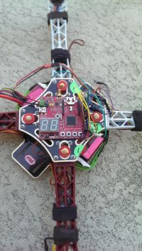
The goal of this project is try to implement the basic function of a drone, fly and controlling the direction by remote control.
Parts List & Cost
| Item# | Part Desciption | Manufacturer | Qty | Cost |
|---|---|---|---|---|
| 1 | SJ One Board | 1 | $80.00 | |
| 2 | NEEWER® HJ450 4-Axis Frame | 1 | $15.99 | |
| 3 | Afro ESC 20Amp Multi-rotor Motor Speed Controller | 4 | $83.96 | |
| 4 | Spektrum 5520 DX5e DSMX 5 Channel TX/RX | 1 | $59.99 | |
| TOTAL | $?? |
Design & Implementation
PWM
The four motor on the drone is controlled by the PWM (Pulse Width Modulation). SJSUone board already gave us a good library to use, so we just have to set the frequency and pin number at the beginning of the code.
The example of using the library.
#include "lpc_pwm.hpp"
#include "uart0.hpp"
#include "stdio.h"

#define PWM_FREQ 500

void motor_test()
{

    PWM servo1(PWM::pwm1, PWM_FREQ);
    PWM servo2(PWM::pwm2, PWM_FREQ);
    PWM servo3(PWM::pwm3, PWM_FREQ);
    PWM servo4(PWM::pwm4, PWM_FREQ);


    Uart0& terminal = Uart0::getInstance();
    terminal.init(38400);

    float p;
    int num;

    while(1){

        printf("NO=");
        scanf("%d",&num);
        printf("pwm percent=");
        scanf("%f", &p);

        switch(num){

            case 1:
                servo1.set(p);
                break;

            case 2:
                servo2.set(p);
                break;

            case 3:
                servo3.set(p);
                break;

            case 4:
                servo4.set(p);
                break;

            default:
                return;
        }
    }
}
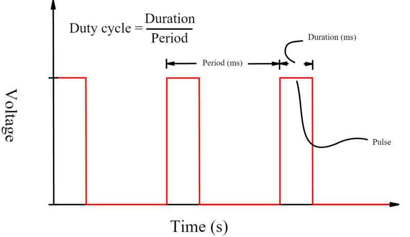
Here is a diagram shows the output of the PWM. PWM_FREQ variable from the previous sample code can control the period and p variable can control the duration.
For a drone, a shorter period of PWM can have better performance, more stable, but the range of the controlling will be smaller if we decrease the period. For example, my system is using 500 Hz PWM and my control range will be about 53% to 100% because the motor will start to rotate at 53%. However, if we change the frequency to 1000 Hz, the motor will start to rotate at 90%, so the the control range will be 90% to 100%. Therefore, we have to find the balance of the performance and the control range.
For controlling the motor, we have to set PWM frequency in every certain period very precisely, so delay function can not satisfy our need. Fortunately, FreeRTOS have the timer interrupt API that can execute the code in period. Here we are talking about the control rate that is different from the PWM rate. The control rate should lower than the PWM rate and the data rate from sensor. For my experiment, 50 Hz is enough to fly but hard to control it. If you want to control it, my recommendation is higher than the 150 Hz.
Here is part of my code.
void motor_control(void *p)
{

        TickType_t xLastWakeTime;
        int period_ms=2;// control rate (500 MHz)
        const TickType_t xFrequency = MS_TO_TICK_RATE(period_ms);
        PWM servo1(PWM::pwm1, 500);
	PWM servo2(PWM::pwm2, 500);
	PWM servo3(PWM::pwm3, 500);
	PWM servo4(PWM::pwm4, 500);

        xLastWakeTime = xTaskGetTickCount();


        while(1)
	{


                //PID control code is in here

		vTaskDelayUntil( &xLastWakeTime, xFrequency ); //every 2ms the system will execute the code below


                #ifdef Y_AXIS_ACTIVE
		servo1.set(pServ1);  //pServ1 will be the % of output for the next period
		servo3.set(pServ3);
                #endif


                #ifdef X_AXIS_ACTIVE
		servo2.set(pServ2);
		servo4.set(pServ4);
                #endif
        }


}Conclusion
Project Video
Upload a video of your project and post the link here.
first lunch of the SJSU drone https://youtu.be/lzpCwFyz_Yk
first fly of the SJSU drone https://youtu.be/GKQJtUIinW8
second fly of the SJSU drone https://youtu.be/MFJ1-ZD47U0
third fly of the SJSU drone https://youtu.be/MBFmyweXbKY
final release of the SJSU drone https://youtu.be/Tv8Bm9wMOkI
final release of the SJSU drone 1 https://youtu.be/xEOyXph9FBg

