Difference between revisions of "S15: Wizard's Chess System"
(→Team Members & Responsibilities) |
(→Team Members & Responsibilities) |
||
| Line 9: | Line 9: | ||
=== Team Members & Responsibilities === | === Team Members & Responsibilities === | ||
* Yaron Alexandrovich | * Yaron Alexandrovich | ||
| − | ** XY Plotter Construction, Hardware | + | ** XY Plotter Construction, Electronic Hardware/Wiring, XY Plotter Driver and Functions on SJOne Board |
* Emil Kurian | * Emil Kurian | ||
** XY Plotter Construction, Case Design, Electromagnet | ** XY Plotter Construction, Case Design, Electromagnet | ||
Revision as of 10:22, 27 May 2015
Contents
Wizard's Chess System
Abstract
The purpose of this project is to create an automated chessboard, displaying moves made by users playing chess. The web application server will be hosted on a Beaglebone Black. Users log in and play a chess game hosted using Node.js. As moves are made on the web app,the pieces will be physically moved on the chessboard.
Objectives & Introduction
Show list of your objectives. This section includes the high level details of your project. You can write about the various sensors or peripherals you used to get your project completed.
Team Members & Responsibilities
- Yaron Alexandrovich
- XY Plotter Construction, Electronic Hardware/Wiring, XY Plotter Driver and Functions on SJOne Board
- Emil Kurian
- XY Plotter Construction, Case Design, Electromagnet
- Gerard Ramos
- Chess Pieces, Case Design, Electromagnet
- Fred Sun
- Server-Side Software, FreeRTOS Environment, UART communication on SJOne Board
Schedule
| Week | Start Date | End Date | Task | Status |
|---|---|---|---|---|
| 1 | 3/27/2015 | 4/10/2015 | Finish building XY Plotter | Completed |
| 2 | 4/12/2015 | 4/26/2015 | Build casing and chessboard | Completed |
| 3 | 4/12/2015 | 4/19/2015 | Build/Control Electromagnet | Completed |
| 4 | 4/12/2015 | 4/15/2015 | Find/Buy appropriate magnets | Completed |
| 5 | 4/12/2015 | 4/19/2015 | Write drivers for XY-Plotter | Completed |
| 6 | 4/12/2015 | 4/19/2015 | Design web application GUI (Front-end) | Completed |
| 7 | 4/12/2015 | 4/26/2015 | Host Web Server on Campus | Completed |
| 8 | 4/19/2015 | 4/26/2015 | 3D print chess pieces + attach magnets to pieces | Completed |
| 9 | 4/19/2015 | 5/3/2015 | Develop Web Server Back-end | Completed |
| 10 | 4/26/2015 | 5/3/2015 | Write functions for plotter to move chess pieces | In Progress |
| 11 | 5/3/2015 | 5/10/2015 | Setup communication protocol between SJOne and Web Server | Completed |
| 12 | 5/3/2015 | 5/17/2015 | FreeRTOS Environment | In Progress |
| 13 | 5/15/2015 | 5/23/2015 | Debug, Debug, Debug | In Progress |
Parts List & Cost
| # | Item | Cost | Quantity | Total Cost |
|---|---|---|---|---|
| 1 | XY Plotter | $300 | 1 | $300.00 |
| 2 | Wood | $10 | 3 | $30.00 |
| 3 | Pololu Stepper Drivers | $6 | 2 | $12 |
| 4 | Perfboard | .50 | 2 | $1.00 |
| 5 | BeagleBone Black | 60 | 1 | $60.00 |
| 6 | 42BYG Stepper Motor | $20 | 2 | $40 |
| 7 | 34 Pin Ribbon Cable | $3 | 1 | $3 |
Design & Implementation
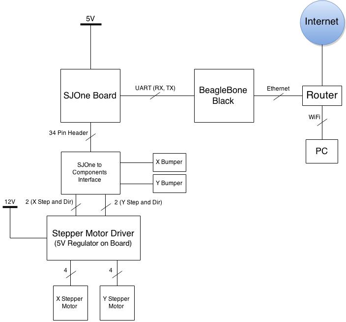
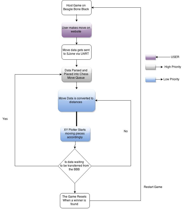
The chess game is hosted on a Beaglebone Black (BBB). The BBB is a open-source hardware single-board computer that runs an embedded Linux. The server back-end is powered by Node.JS, and ran as a local host such that any computer device can connect to it and play the game. As plays are made on the chess game, the changes in piece position are processed, and a string is transmitted over UART to the SJOne board. The SJOne interprets the string, and translates these to physical moves. By commanding the stepper motors and electromagnet, it moves chess pieces to reflect the changes made in game.
Hardware Design
Hardware Interface
X-Y Plotter
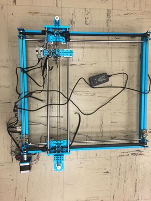
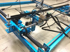
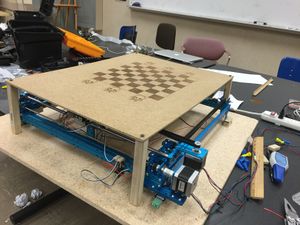
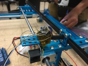
Initially, when looking for a solution for control on the XY plane, we looked for a pen plotter. We found none. After searching, we found an XY plotter kit by Makeblock. The plotter has a usable area of 15" x 12", with each axis driven by a stepper motor.
Chessboard
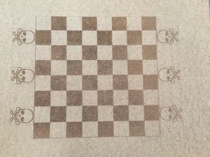
The layout for the chessboard was designed in SolidWorks. The design was then rastered onto a piece of wood with a laser cutter. It has a playable grid of 11" x 11", with 2" graveyard at the bottom and top of the Y axis, and 1/2" margins at the left and right of the X axis. This is to maximize the usable area of the XY plotter.
Computer Aided Design Chess Pieces
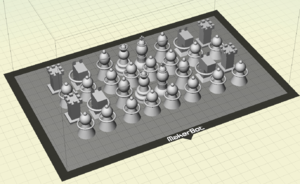
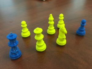
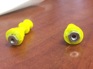
Our chess pieces were 3d printed, one set blue and one set yellow (Spartan colors). The pieces were designed significantly smaller than the chess board, such that a piece can slide over between squares, without disturbing other pieces. We opened the bottom of the piece by melting the plastic with a soldering iron, and fixed a magnet and a washer to the inside of each peace. This was to allow the electromagnet underneath to grip the piece.
Electromagnet
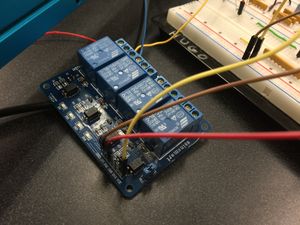
An electromagnet is just a wire wound around a piece of metal. To make ours, we used magnet wire, a thin wiring with very minimal insulation to allow magnetic fields to pass through. We wrapped wire around a nail. To lower the resistance of the wire, we wound 3 wires in parallel. This gave us the same number of loops with less wire (less resistance) for the current to pass through. The magnet was driven high by a 12 volt, 2 amp power source. A relay was toggled on/off by the SJOne board, turning on/off the magnet. The relay was protected by a flyback diode.
Stepper Motor Driver
Stepper motors work by having four electromagnets that magnetically grip a bar. By flipping these magnets on and off in a circular pattern, the bar rotates.
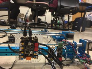
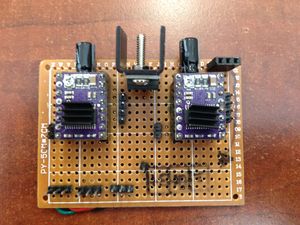
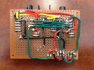
In order to use the stepper motors, 2 processes needed to occur. The first was setting the stepper motor driver. Our Drivers were the MD20B stepper motor drivers from Pololu, based on the DRV8825 IC from TI. In order to use these drivers, we had to manually set the step size (we chose an 1/8 step) and attach the power source we would be using. The logic was taken from the SJone, and the external power came from a 12V, 2A power supply.
To control the electromagnets at 1/8th step, a sine wave is passed through the electromagnets at a very specific rate. Feeding this sine wave too fast or too slow will fail to grip and step the stepper motor properly, so a perfectly calibrated feed rate is required.
Software Design
Software Flowchart
Server-Side Software
The code used for server-side can be viewed here (GitHub).
Note: If used on a BeagleBone Black, UART4 needs to be initialized.
Front-End
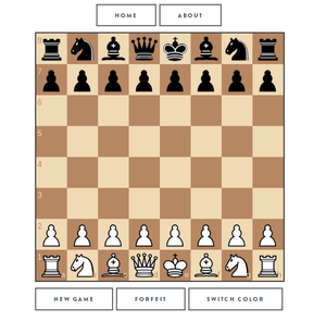
The front-end of the application was built using HTML, CSS, and JavaScript. The HTML was converted to Jade for readability. The front-end is comprised of 3 pages: Home, Play, and About. Bootstrap by Twitter was also used for it's nicely designed elements and ease of implementation. The graphical chessboard and its pieces was implemented in a JavaScript library called chessboardjs. It provided easy to use libraries to display the chessboard in the desired orientation.
Back-End
Several frameworks were used when creating the back-end of the server. JavaScript was used because it allows everything on the server-side to be integrated together nicely without having to use multiple programming languages.
Node.js was used as the environment for the server-side application.
Express.js was used to hold all the middleware together.
Socket.io was used as the library to allow for real-time communication between web pages.
Chess.js is a JavaScript library that we used to make sure the moves made are valid.
Node.js Serial Port is a library that allows for communication to the SJOne Board via UART.
When a user logs into the 'Play' page, socket.io will designate that user to a specific socket. If another user logs onto the play page, they will both be running off the same socket. This allows for the real-time aspect. When the user makes a move a string will be sent to the SJOne Board via UART.
//Snippet of Server-side code
//This is the packing of the UART String
socket.on('clientUpdateRequest', function(data,last){
	currentfen = data;
	var lm = last;
	var cap = lm['captured'];
	socket.broadcast.emit('updateGameFromServer',currentfen);

	if(cap == undefined) //no piece was captured, just a normal move
	{
	  //Move
	  ser.write('M');
	  ser.write(lm['from']);
	  ser.write(lm['to']);
	}

	else
	{
	  //Kill
	  ser.write('K');
	  ser.write(lm['captured']);
	  ser.write(lm['color']);
	  ser.write(lm['to']);
	  //ser.write('\n');
	  //Move
	  ser.write('M');
	  ser.write(lm['from']);
	  ser.write(lm['to']);
	  //ser.write('\n');
	}
});
When a move is made on the hosted chess game, the move is generated as a string and passed into the SJOne board via UART. The string will be something like 'M','A','2','C','5'. The first letter is the type of move it makes. Either moving a piece, or killing a piece. Then, positions two and three are the initial X and Y coordinates of the piece to move. Positions 4 and 5 are the final X and Y coordinates of the piece to move.
Embedded Software
Tasks and Semaphores
A FreeRTOS system was used to hold our system together. We used 2 tasks. One task was used at high priority (getFromBBB) to store UART strings into a character queue. This was set at high priority because the inputs coming from the web application should not be delayed.
//Task 1, High Priority
void getFromBBB(void* p)
{
    char uart_basket[6] = {};
    while(1)
    {
        if(xSemaphoreTake(uart2InterruptSemaphore, portMAX_DELAY))
        {
            uart2Inst.gets(uart_basket,5,portMAX_DELAY);
            if(xSemaphoreTake(chessMoveSemaphore, portMAX_DELAY))
            {
                for(int i = 0; i < 5; i++)
                {
                    xQueueSend(chessMoveQueue, uart_basket+i, portMAX_DELAY);
                }
                xSemaphoreGive(chessMoveSemaphore);
            }
        }
    }
}
The second task is for the plotter to move (chessMoveProcess). This is set at a lower priority. When there is is an item in the queue the task unblocks and the plotter is able to move. The semaphore used here is to only allow one task to access the chess queue at a time.
//Task 2, Medium Priority
void chessMoveProcess(void* p)
{
    char currChar = '\0';
    bool readyToMove = false;
    uint8_t charCount = 0;
    char uart_basket[6] = {};
    while(1)
    {
        if(xSemaphoreTake(chessMoveSemaphore, portMAX_DELAY))
        {
            if(xQueueReceive(chessMoveQueue, &currChar, 0))
            {
                if(charCount == 4)
                {
                    uart_basket[4] = currChar;
                    uart_basket[5] = '\0';
                    readyToMove = true;
                }
                else
                {
                    uart_basket[charCount] = currChar;
                    charCount++;
                }
            }
            xSemaphoreGive(chessMoveSemaphore);
        }

        if(readyToMove == true)
        {
            readyToMove = false;
            charCount = 0;
            //Move Functions Here
        }
}
UART
The UART receive was done by using the pre-built drivers in the SJOne Package. We set the baud rate at 9600. The UART is set to interrupt when there is a character available. When the interrupt occurs a semaphore is given so that a task is unblocked.
//UART Interrupt
void UART2_IRQHandler(void)
{
    uart2Inst.handleInterrupt();
    xSemaphoreGiveFromISR(uart2InterruptSemaphore,NULL);
}

//UART INIT
Uart2& uart2Inst = Uart2::getInstance();
uart2Inst.init(9600);
isr_register(UART2_IRQn, UART2_IRQHandler);
Stepper Driver
The code for the stepper driver can be viewed here.
The XY plotter came with an Arduino and source code to power the plotter. We ported the Arduino code over to the SJOne, modifying it to work on the SJOne platform.
Our driver consisted of a series of helper functions, as well as three main functions: set_position(x position, y position) set_target(x target, y target) dda_move(feedrate)
x position and y position are NOT tick locations. These represent physical locations in the X and Y grid. The helper functions convert these into number of ticks. The feedrate is the speed at which the sine wave is pulsed through the stepper motor to achieve 1/8th step twitches.
set_position stores a positional value that the plotter is currently at. set_target stores a value that the stepper motor wants to achieve. Then the number of steps for x and y to achieve this position are calculated. dda_move is the move function. This creates an x step and y step counter, then steps the x and y stepper motors until the counters are maxed out. Then the x position and y position are updated.
Using the set_target, set_position, and dda_move, move routines to move the pieces were coded.
Move Routines
The code for the move routines can be viewed here.
moveToOrigin(): This moves the stepper motors to the origin.
moveToBoard(): This moves the stepper motors to the first square on the 8x8 chess board.
moveInGrid(x, y): This moves the stepper motors to the designated x and y position of the 8x8 chess board.
moveToPassingLaneX(): This moves a chess piece off the center of the square, so that it can navigate around other pieces.
moveToPassingLaneY(): Same, but for y-axis.
moveOffPassingLaneX(): Returns piece to center of grid from x-axis passing lane.
moveOffPassingLaneY(): Returns from y-axis passing lane.
moveToGraveyardB(): Once a piece is gripped, it moves that piece into the x passing lane, than carries it to its graveyard.
moveToGraveyardW(): Same, but for the white team's graveyard.
Once a command comes in, for example a move command, it executes a series of move routines. First, move to board buts the plotter in position [1][1]. Then, moveInGrid(initial X, inital Y) grips the piece to be moved. Then moveToPassingLaneX and moveToPassingLaneY positions the piece to move around other chess pieces. Then, moveInGrid(final X, same Y) is called to move to the proper X location. Then, moveInGrid(same X, final Y) is called to move to the final Y position. Then moveOffPassingLaneX and moveOffPassingLaneY centers the piece in its final resting location. Finally, moveToOrign is called, moving the plotter to its resting position.
Implementation
The chess game was implemented using Node.JS, hosted on a Beaglebone Black. To access the game, any internet device would connect to the local Wifi hosting the BBB, and enter the IP address into the address bar: 192.168.1.136:3030.
The Chess game compiles itself into a 64 character long string, describing the entire board. When a move is made, the change in positions are parsed out of the string, and a command is transmitted over UART to to the SJOne board. The SJOne uses UART2 to receive the signal. When a character comes in, an interrupt is thrown on the SJOne. As characters come in, a string is appended with the received character, until \n is received. Upon \n, the string is thrown into a queue.
To service a string, the first character is examined. Depending on that letter, the matching set of move routines are called. The piece locations to be moved are parsed out of the string, and passed into the move routines, which include timed instructions to the stepper motors.
Therefore, the moves made in the chess game are physically expressed on the board.
Technical Challenges
Issue #1: Stepper Motor Drivers
As current flows into a stepper motor, it stores this energy in magnetic fields. The reverse is true. That is, when current is no longer supplied to the motor, the magnetic field collapses creating current, known as back EMF. The stepper motor drivers contain circuitry to protect itself from this back EMF. However, adjusting the current setting or unplugging the stepper motor driver while engaged WILL damage the driver.
Issue #2: Electromagnet
One of the other issues we encountered was with safety regarding the electromagnet, mainly due to heat, one of the things we wanted to calculate was how much current to run through the electromagnet in order to start moving pieces. As we were doing our test, the way that the electromagnet moved under the board scraped little pieces of wood on it. After a couple of minutes of testing we noticed smoke coming from the bottom of the board, at first we thought it was the electromagnet heating up the board way too much but actually the issue was the the little pieces of wood was going on the electromagnet, and due to the high amount of heat this caused the wooden dust to burn. After noticing this fire hazard we decided to not use the electromagnet anymore because it wasn't worth the risk if anything catching on fire.
Issue #3: Stepper Motor Calibration
The XY Plotter was purchased from MakeBlock. The kit included a portion of code to control the stepper motor. The code is originally written for the Arduino so it needed to ported over to the SJOne Board. However, once the code was ported over, there were several #defines and const variables on the Arduino side that did not match on the SJOne Board. We needed to calibrate the stepper so that it performs exactly how it does on the Arduino side.
Issue #4: Stepper Motor Timing
Stepper motors have to be perfectly timed. They store current flowing through them in a magnetic field, then a rising edge pulse switches the field from one electromagnet to the next. This timing cycle needs to be perfect. When FreeRTOS context switches the stepper motors are no longer receiving a current, and lose their magnetic fields. Then, the context switch back to the stepper driver re-engergizes them. This causes unpredictable, uncontrolled behavior, and the stepper motors stutter and struggle to move.
Conclusion
We set out to create a Chess Board that could move the pieces by itself based on a game being played online. Instead, we created a potential fire hazard. After realizing that we created a potential fire hazard, we changed around a few things and instead created what was originally intended, a Wizard's Chess System. The Wizard's Chess possesses the ability to engage multiple players and move the pieces across the board via magnets underneath, suggesting to an errant watcher that the board indeed is magical.
As mentioned before, there were a few hiccups like the potential fire hazard. Testing and debugging the chess board was its own task because of the drivers we created from scratch. The motor drivers weren't as robust as we would have liked, wasting time and resources just to replace the driver over simple issues. Not to mention the testing that had to be done each phase such as how much power was going into each component or making sure that all the hardware was aligned in order to ensure that the precision we needed was there to play the game.
Overall, it would seem that a lot of effort went into creating a "over-the-top" version of a simple game. However, the chessboard we created draws from the various lessons learned though this class the and years we have been in engineering. A UART driver was implemented between two microcontrollers and ensured that the transmissions were read and properly processed. A driver was created for the XY Plotter from scratch, with all locations being mapped and programmed accordingly. An electromagnet was created, and though ultimately scrapped, it was successful in its intended purpose. FreeRTOS was used to prioritize the tasks of our board in order to ensure that all necessary functions were carried out properly and efficiently. By working on this project, the gap between knowledge attained in class and the actual implementation of these lessons was bridged.
Project Video
Video will be up soon!
Project Source Code
References
Acknowledgement
Special thanks to Hugo Quiroz. He provided mechanical knowledge, access to laboratory and equipment, and dedication to our project. Thanks for the measures, cuts, materials, and laser cutter to etch our chess board.
Special thanks to Professor Peter Reischl. He went out of his way to educate us on constructing the electromagnet. Thanks for going out of your way to provide the knowledge and verification to construct our electromagnet.
Special thanks to Preetpal Kang. His SJOne development platform and dedication to San Jose State University made this project possible.
Appendix
Instructable on how to control a stepper motor:
http://www.instructables.com/id/How-to-use-a-Stepper-Motor/
Assembly instructions for the linear plotter:
http://learn.makeblock.cc/learn/resources/XY-plotter-V2.02-full-package/XY-Plotter-V2.02-Assembly-instructions.pdf
