Difference between revisions of "S15: Vision RC Car"
Proj user3 (talk | contribs) (→Grading Criteria) |
Proj user3 (talk | contribs) (→Project Video) |
||
| (28 intermediate revisions by the same user not shown) | |||
| Line 7: | Line 7: | ||
== Objectives & Introduction == | == Objectives & Introduction == | ||
| − | The Vision RC Car, here on out known as the system, was initially designed to spy on people. A user will have the ability to access a video-feed from the system, in addition to the ability to control the | + | The Vision RC Car, here on out known as the system, was initially designed to spy on people. A user will have the ability to access a video-feed from the system, in addition to the ability to control the propulsion and steering motors of the system, through the web-based GUI. It was determined that in addition to any nefarious activities that could be conducted with the system, a user could also utilize the system to make deliveries of small packages, to explore spaces inaccessible to humans, and for hobbyist purposes. |
| − | The system is composed of a gutted RC car, a dual-bridge motor controller, the | + | The system is composed of a gutted RC car, a dual-bridge motor controller, the SJ One microcontroller, the Intel Edison microcontroller, and a webcam. At the center of the system is the Edison, which runs a lightweight Linux distro known as Yocto. The Edison is WiFi capable and will serve as the system bridge to wireless networks. The Edison will run a Node.js server that will host the system GUI. The webcam is interfaced with the Edison, and the video-feed is presented on the GUI. The system will utilize JavaScript to read commands from the user, and redirect the commands received to the SJSU One. |
The SJSU One and Edison communicate through UART at a baud rate of 115200. The SJSU One will control the speed and direction of the system by interfacing with the dual-bridge motor-controller, which in turn drives the two-motors of the system. One of the motors is responsible for forward and backward movements, while the other motor is responsible for steering. | The SJSU One and Edison communicate through UART at a baud rate of 115200. The SJSU One will control the speed and direction of the system by interfacing with the dual-bridge motor-controller, which in turn drives the two-motors of the system. One of the motors is responsible for forward and backward movements, while the other motor is responsible for steering. | ||
| Line 127: | Line 127: | ||
=== Hardware Design === | === Hardware Design === | ||
| − | The hardware | + | The hardware design incorporates five major devices: the Intel Edison, SJ One, motor controller, power-supply, and the web-cam. The Vision RC car uses a 12V battery pack to power the SJSU One, the motor controller, and the Intel Edison. The power-supply utilizes 8 AA batteries. The Edison is the center of the system. The Edison accepts user input, and translates that data to the SJ One through UART. The UART is operating on standard 8N1, at a baudrate of 115200. The SJ One accepts single-character commands for the standard movement keys W, A, S, and D. The characters determine what digital signals the SJ One sends to the motor-controller, which subsequently drives the system. The webcam is directly interfaced to the Edison, which can act as a host to a peripheral device when powered by 7V-15V. The webcam feed is processed and displayed to the user on the web-browser. |
| − | [[File: S15 244 G8 | + | [[File: S15 244 G8 new Hardware Design2.jpg|700px|center]] |
==== Intel Edison ==== | ==== Intel Edison ==== | ||
| Line 142: | Line 142: | ||
[[File: S15 244 G8 L298ndiagram.jpg|500px|left]] | [[File: S15 244 G8 L298ndiagram.jpg|500px|left]] | ||
[[File: S15 244 G8 L298n.png|250px|center]] | [[File: S15 244 G8 L298n.png|250px|center]] | ||
| − | + | <br> | |
| − | |||
==== USB Web Cam ==== | ==== USB Web Cam ==== | ||
| Line 151: | Line 150: | ||
=== Hardware Interface === | === Hardware Interface === | ||
The primary hardware interfaces are from the Intel Edison to the SJ One, from the SJ One to the Dual-Bridge Motor Controller, and from the motor controller to the two motors. The Edison's UART1_TX pin is connected to the SJ One's RXD3 ping. The Edison interprets command input from the user, and serially outputs a character to the SJ One. The SJ One takes the Edison's commands, and outputs the appropriate digital signals to the motor controller. The motor controller drives the steering and propulsion motors. | The primary hardware interfaces are from the Intel Edison to the SJ One, from the SJ One to the Dual-Bridge Motor Controller, and from the motor controller to the two motors. The Edison's UART1_TX pin is connected to the SJ One's RXD3 ping. The Edison interprets command input from the user, and serially outputs a character to the SJ One. The SJ One takes the Edison's commands, and outputs the appropriate digital signals to the motor controller. The motor controller drives the steering and propulsion motors. | ||
| + | <br><br> | ||
| + | [[File: S15 244 G8 new Software.jpg|450px|left]] | ||
| + | [[File: S15 244 G8 Basic new.jpg|400px|center]] | ||
=== Software Design === | === Software Design === | ||
| − | |||
The software design on the SJ One utilized FreeRTOS queue's for cooperative context switching, as well as the UART driver's provided with the development environment. The UART3 driver was contained within the "command" task, and would wait infinitely for data, in the form of single characters, to be received from the Intel Edison. Once the data is received, the command task distributes the command to the appropriate task. The three task's that wait for commands are in charge of steering, propulsion, and combined steering and propulsion commands. The motor controller has two inputs for each bridge. Mismatching digital signals, e.g. H and L, drive the motors, while equal digital signals turn the motor controller off. In the case of the combined commands task, all four signals are distributed. | The software design on the SJ One utilized FreeRTOS queue's for cooperative context switching, as well as the UART driver's provided with the development environment. The UART3 driver was contained within the "command" task, and would wait infinitely for data, in the form of single characters, to be received from the Intel Edison. Once the data is received, the command task distributes the command to the appropriate task. The three task's that wait for commands are in charge of steering, propulsion, and combined steering and propulsion commands. The motor controller has two inputs for each bridge. Mismatching digital signals, e.g. H and L, drive the motors, while equal digital signals turn the motor controller off. In the case of the combined commands task, all four signals are distributed. | ||
| − | + | [[File: S15 244 G8 FlowDiagramRTOS.jpg|500px|center]] | |
The Edison software design was composed of shell scripts, JavaScript, and the Yaler. The shell scripts were utilized to open the UART1 serial ports on the Edison. A shell script was designed open the necessary serial port, start the server, and create the Yaler tunnel. Yaler, Yaler.net, provides Connectivity as a Service. The Yaler application is un-packaged and run on the Edison, which creates a web-tunnel that is accessible through the use of a relay domain provided by Yaler.net. | The Edison software design was composed of shell scripts, JavaScript, and the Yaler. The shell scripts were utilized to open the UART1 serial ports on the Edison. A shell script was designed open the necessary serial port, start the server, and create the Yaler tunnel. Yaler, Yaler.net, provides Connectivity as a Service. The Yaler application is un-packaged and run on the Edison, which creates a web-tunnel that is accessible through the use of a relay domain provided by Yaler.net. | ||
Lastly, the server was created using a combination of node.js and express. When the server is up and running, it will serve one page at a time to users. The page can be accessed by using the devices ip at port 8080, or if a user is on an external network to the Edison, the Yaler domain will redirect users to the Vision RC Car. The web-GUI presents the user a video-feed from the Edison, and takes key commands from the user to drive the RC car. The reading of the key commands is done with the help of the Mousetrap library | Lastly, the server was created using a combination of node.js and express. When the server is up and running, it will serve one page at a time to users. The page can be accessed by using the devices ip at port 8080, or if a user is on an external network to the Edison, the Yaler domain will redirect users to the Vision RC Car. The web-GUI presents the user a video-feed from the Edison, and takes key commands from the user to drive the RC car. The reading of the key commands is done with the help of the Mousetrap library | ||
| − | |||
== Implementation == | == Implementation == | ||
| − | ==== | + | ==== Motor Controls ==== |
| − | + | This was implemented by using the SJ one to relay commands from the Intel Edison to the motor-controller. The SJ One utilizes 3 tasks: command, propulsion, and steering. The command task is the highest priority task, priority 4, and waits for WASD commands from the Edison on the UART3 port. The propulsion and steering tasks have a priority of 3. The propulsion and steering task will sleep on an empty queue until the command task sends the appropriate command to the shared queue. Depending on the command received by the propulsion and steering tasks, the SJ One outputs the appropriate digital signals to the motor-controller, that in turn drives the motor. The digital signals drive the motor-controller for a minimum of 50ms. | |
| − | + | ||
| − | + | ==== Server to Client Communication ==== | |
| − | + | ||
| − | + | The client and server communicate through web-sockets. The io.socket JavaScript library was utilized for the implementation of the sockets. | |
| − | ==== | + | ==== Server ==== |
| − | + | ||
| − | + | The server was implemented on the Intel Edison. The server consisted of node.js and express. Initially, a server was made that could present the user with any .html file that existed, but later on in the project when the webcam server was integrated, this functionality was lost. The implemented server was a modified version of the webcam server created by Dr. Esther Jun Kim. This server was hard-coded to present users with the "index.html" file. Dr. Kim's code can be found at https://github.com/drejkim/edi-cam. When a command is received from the client, the server relays the message to the SJ One board. | |
| − | + | ||
| − | + | ==== Client ==== | |
| + | |||
| + | The client is presented the index.html page by the server. The page is very spartan, and only contains a centered video-feed from the webcam, and waits for input key commands from the user. | ||
| + | |||
| + | ==== Key Reading ==== | ||
| + | |||
| + | The Mousetrap JavaScript library was used to bind keys to functions that would output commands from the Intel Edison to the SJ One. When a key is pressed, a command is sent from the client to the server via the web-sockets. | ||
| + | |||
| + | ==== Serial Communication ==== | ||
| + | |||
| + | The UART3 API for the SJ One was utilized to implement serial communication. On the Intel Edison stty was utilized to open the UART1 port. When the client sends a command to the server, the server relays that message to the SJ One board through the use of the "serialport" JavaScript library. | ||
== Testing & Technical Challenges == | == Testing & Technical Challenges == | ||
| − | |||
| − | |||
| − | |||
| − | |||
=== Issue #1 === | === Issue #1 === | ||
| Line 186: | Line 192: | ||
'''Solution''' - Research and use a communication protocol from client to server. Our choice was socket.io. | '''Solution''' - Research and use a communication protocol from client to server. Our choice was socket.io. | ||
| + | |||
| + | === Issue #2 === | ||
| + | |||
| + | === Issue #3 === | ||
| + | |||
| + | === Issue #4 === | ||
== Conclusion == | == Conclusion == | ||
| Line 191: | Line 203: | ||
=== Project Video === | === Project Video === | ||
| − | + | https://youtu.be/WNrr4Xq1Ctg | |
=== Project Source Code === | === Project Source Code === | ||
| Line 204: | Line 216: | ||
http://tronixlabs.com/news/tutorial-l298n-dual-motor-controller-module-2a-and-arduino/ | http://tronixlabs.com/news/tutorial-l298n-dual-motor-controller-module-2a-and-arduino/ | ||
| + | |||
| + | https://github.com/drejkim/edi-cam | ||
| + | |||
| + | http://socket.io/ | ||
Latest revision as of 02:57, 27 May 2015
Contents
Vision RC Car
Abstract
The Vision RC Car will provide a video feed and controls to a user through a web-based GUI, with the goal of being able to roam wherever a network may be available.
The goal of the Vision RC Car is to be able to roam wherever a WiFi network is present. A user will utilize a web-based GUI to view a video-feed from the platform, and in turn control the vehicle from the GUI.
Objectives & Introduction
The Vision RC Car, here on out known as the system, was initially designed to spy on people. A user will have the ability to access a video-feed from the system, in addition to the ability to control the propulsion and steering motors of the system, through the web-based GUI. It was determined that in addition to any nefarious activities that could be conducted with the system, a user could also utilize the system to make deliveries of small packages, to explore spaces inaccessible to humans, and for hobbyist purposes.
The system is composed of a gutted RC car, a dual-bridge motor controller, the SJ One microcontroller, the Intel Edison microcontroller, and a webcam. At the center of the system is the Edison, which runs a lightweight Linux distro known as Yocto. The Edison is WiFi capable and will serve as the system bridge to wireless networks. The Edison will run a Node.js server that will host the system GUI. The webcam is interfaced with the Edison, and the video-feed is presented on the GUI. The system will utilize JavaScript to read commands from the user, and redirect the commands received to the SJSU One.
The SJSU One and Edison communicate through UART at a baud rate of 115200. The SJSU One will control the speed and direction of the system by interfacing with the dual-bridge motor-controller, which in turn drives the two-motors of the system. One of the motors is responsible for forward and backward movements, while the other motor is responsible for steering.
Team Members & Responsibilities
- Team Member 1
- Jonathon Hongpananon - Web Server
- Team Member 2
- Eduardo Espericueta - Motor Control
- Team Member 3
- Shangming Wang - IP Camera Support
Schedule
| Week# | Start Date | End Date | Task | Status | Actual Completion Date |
|---|---|---|---|---|---|
| 1 | 4/14/2015 | 4/20/2015 | Ed: Attach prototyping board to the RC car. Interface the SJSU One and the motor controller. Test the motor tasks, and verify that steering and drive work as expected.
Jon: Research setting up server on Edison. Flash OS onto the Intel Edison. Solder header pins onto the Edison mini breakout board. Eric: Research streaming camera feed. Create system layout diagram. |
Complete - Motors respond to 'a', 'w', 's', & 'd' terminal commands. Front wheels turn left and right. | 4/20/15 |
| 2 | 4/21/2015 | 4/27/2015 | Ed: Modify the Edison’s web page to form a first draft of what UI will look like. Write JavaScript for UI that will detect a user’s keyboard input.
Jon: Setup node.js server from Edison. Attempt first draft webserver implementation. Eric: Setup streaming camera feed to browser - Part 1 |
Complete - Node.js server is setup and tested. Javascript page is able to echo key commands to console. | 4/27/15 |
| 3 | 4/28/2015 | 5/4/2015 | Ed: Integrate the Edison and the SJSU One. Write code to transfer command input from UI to the SJSU One.
Jon: Continuation of node.js server. Expand UI aesthetics and functionality. Eric: Setup streaming camera feed to browser - Part 2 |
Complete | 5/19/15 |
| 4 | 5/5/2015 | 5/11/2015 | Ed: Integration on RC car platform, more specifically wiring layout, color, and verification of connections.
Jon: Integration on RC car platform (power supply) Eric: Integration on RC car platform (mounting) |
Complete | 5/21/15 |
| 5 | 5/12/2015 | 5/18/2015 | Ed: Test motor controls from web GUI.
Jon: Test accessibility and physical range. Eric: Test webcam at distance. |
Complete | 5/23/15 |
| 6 | 5/19/2015 | 5/22/2015 | Ed: Finish details. Work on Wiki.
Jon: Finish details. Work on Wiki. Eric: Finish details. Work on Wiki |
Complete | 5/24/15 |
Parts List & Cost
| Qty | Description | Manufacturer | Part Number | Total Cost |
|---|---|---|---|---|
| 100 | Jumper Wires | $6.99 | ||
| 1 | DC Stepper Motor | $6.43 | ||
| 40 | Male to Female Jumper Wires | $4.99 | ||
| 10 | PCB Board Pin Headers | $5.74 | ||
| 200 | Cable Ties | Turnigy | $6.31 | |
| 10 | PCB Female Pin Headers | $5.29 | ||
| 1 | Remote Control Car | $59.99 | ||
| 1 | SJOne Board | $80.00 | ||
| 1 | Intel Edison | Intel | $60.00 | |
| Total Cost (excluding shipping and taxes) | $235.74 |
Design & Implementation
Hardware Design
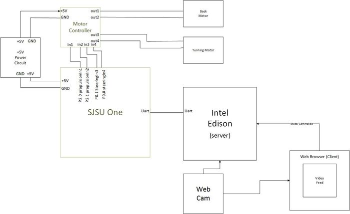
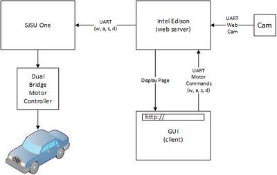
The hardware design incorporates five major devices: the Intel Edison, SJ One, motor controller, power-supply, and the web-cam. The Vision RC car uses a 12V battery pack to power the SJSU One, the motor controller, and the Intel Edison. The power-supply utilizes 8 AA batteries. The Edison is the center of the system. The Edison accepts user input, and translates that data to the SJ One through UART. The UART is operating on standard 8N1, at a baudrate of 115200. The SJ One accepts single-character commands for the standard movement keys W, A, S, and D. The characters determine what digital signals the SJ One sends to the motor-controller, which subsequently drives the system. The webcam is directly interfaced to the Edison, which can act as a host to a peripheral device when powered by 7V-15V. The webcam feed is processed and displayed to the user on the web-browser.
Intel Edison
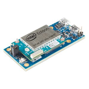
The Intel Edison, released in 2014, is a relatively new, but an extremely powerful SoC. The device is powered by the dual-core Z34XX Atom processor, which is of the x86 architecture. Additionally, there is a Quark microcontroller on board the Edison for real-time applications, but as of Spring 2015 it has not been unlocked for developers. The Edison has 4GB of flash, and 1GB of RAM. The device also has WiFi and Bluetooth capability. The Edison can do it all!
SJ One
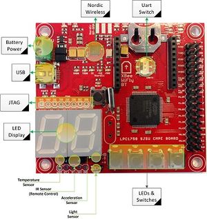
The SJ One board runs FreeRTOS. The board has a number of peripheral's that include: 4 switches & 4 LED's, temperature sensor, IR remote control, 2-Digit 7-Segment Display, and a few others. The device has 512K ROM, 64K RAM, and is powered by the ARM Cortex-M3.
Dual Bridge Motor Controller
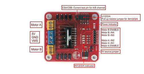
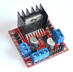
The L298N allows us to control the speed and direction of two DC motors. It can be used with motors that have a voltage of between 5 and 35V DC. It is also capable of outputting 5V with the onboard 5V regulator. These dual motor controllers are inexpensive and make motor control operation a simple task. The motors are connected to the A and B ports of the L298N module. There are 2 ports from the SJSU One board to the L298N which use the PWM pins.
USB Web Cam
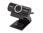
The web cam used in this project is a Creative Live Cam Sync HD sensor. It is a 720p HD sensor capable of up to 30fps @ 1280 x 720 resolution. It is a simple USB web cam that is connected via USB port on the Edison.
Hardware Interface
The primary hardware interfaces are from the Intel Edison to the SJ One, from the SJ One to the Dual-Bridge Motor Controller, and from the motor controller to the two motors. The Edison's UART1_TX pin is connected to the SJ One's RXD3 ping. The Edison interprets command input from the user, and serially outputs a character to the SJ One. The SJ One takes the Edison's commands, and outputs the appropriate digital signals to the motor controller. The motor controller drives the steering and propulsion motors.
Software Design
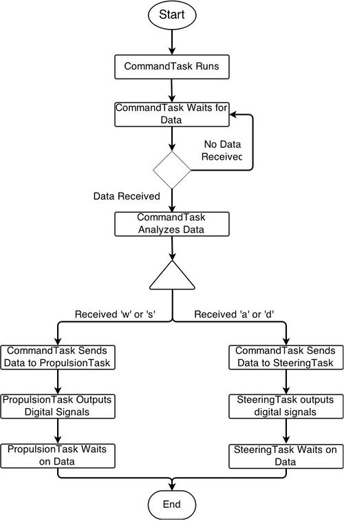
The software design on the SJ One utilized FreeRTOS queue's for cooperative context switching, as well as the UART driver's provided with the development environment. The UART3 driver was contained within the "command" task, and would wait infinitely for data, in the form of single characters, to be received from the Intel Edison. Once the data is received, the command task distributes the command to the appropriate task. The three task's that wait for commands are in charge of steering, propulsion, and combined steering and propulsion commands. The motor controller has two inputs for each bridge. Mismatching digital signals, e.g. H and L, drive the motors, while equal digital signals turn the motor controller off. In the case of the combined commands task, all four signals are distributed.
The Edison software design was composed of shell scripts, JavaScript, and the Yaler. The shell scripts were utilized to open the UART1 serial ports on the Edison. A shell script was designed open the necessary serial port, start the server, and create the Yaler tunnel. Yaler, Yaler.net, provides Connectivity as a Service. The Yaler application is un-packaged and run on the Edison, which creates a web-tunnel that is accessible through the use of a relay domain provided by Yaler.net.
Lastly, the server was created using a combination of node.js and express. When the server is up and running, it will serve one page at a time to users. The page can be accessed by using the devices ip at port 8080, or if a user is on an external network to the Edison, the Yaler domain will redirect users to the Vision RC Car. The web-GUI presents the user a video-feed from the Edison, and takes key commands from the user to drive the RC car. The reading of the key commands is done with the help of the Mousetrap library
Implementation
Motor Controls
This was implemented by using the SJ one to relay commands from the Intel Edison to the motor-controller. The SJ One utilizes 3 tasks: command, propulsion, and steering. The command task is the highest priority task, priority 4, and waits for WASD commands from the Edison on the UART3 port. The propulsion and steering tasks have a priority of 3. The propulsion and steering task will sleep on an empty queue until the command task sends the appropriate command to the shared queue. Depending on the command received by the propulsion and steering tasks, the SJ One outputs the appropriate digital signals to the motor-controller, that in turn drives the motor. The digital signals drive the motor-controller for a minimum of 50ms.
Server to Client Communication
The client and server communicate through web-sockets. The io.socket JavaScript library was utilized for the implementation of the sockets.
Server
The server was implemented on the Intel Edison. The server consisted of node.js and express. Initially, a server was made that could present the user with any .html file that existed, but later on in the project when the webcam server was integrated, this functionality was lost. The implemented server was a modified version of the webcam server created by Dr. Esther Jun Kim. This server was hard-coded to present users with the "index.html" file. Dr. Kim's code can be found at https://github.com/drejkim/edi-cam. When a command is received from the client, the server relays the message to the SJ One board.
Client
The client is presented the index.html page by the server. The page is very spartan, and only contains a centered video-feed from the webcam, and waits for input key commands from the user.
Key Reading
The Mousetrap JavaScript library was used to bind keys to functions that would output commands from the Intel Edison to the SJ One. When a key is pressed, a command is sent from the client to the server via the web-sockets.
Serial Communication
The UART3 API for the SJ One was utilized to implement serial communication. On the Intel Edison stty was utilized to open the UART1 port. When the client sends a command to the server, the server relays that message to the SJ One board through the use of the "serialport" JavaScript library.
Testing & Technical Challenges
Issue #1
Issue - Originally, we were listening for user keyboard commands built into the server, but we later realized that there is a distinct difference between the server and client side of the NodeJS server. The original code listening for keyboard input was being displayed on the console but not being directed to UART serial.
Solution - Research and use a communication protocol from client to server. Our choice was socket.io.
Issue #2
Issue #3
Issue #4
Conclusion
In conclusion, we learned a lot from this project. At first, we thought this project was going to be semi-easy considering it was just using UART communication from an Edison to the SJSU One board. What proved to be a difficult task was learning the IoT aspects of the Edison. At one point, we were able to have a web cam feed, a simple web-page with simple buttons, and console output from keyboard commands, but integrating them all together proved to be the most difficult task. Integration was the most challenging part of the entire project because of dependencies and syntax. We have learned many valuable things from this project and hope to use lessons learned for future work. This project has expanded our knowledge because we learned that team-work and task-utilization is critical. We mustn't waste time and if we plan ahead then our time will be used more efficiently. This is where the design process before actual design is critical. Teamwork is also critical because one person alone cannot complete all of the components themselves. If there is teamwork then the project flow will be much more efficient.
Project Video
Project Source Code
References
Acknowledgement
Any acknowledgement that you may wish to provide can be included here.
References Used
http://www.intel-software-academic-program.com/pages/courses
http://tronixlabs.com/news/tutorial-l298n-dual-motor-controller-module-2a-and-arduino/
