Difference between revisions of "S15: Wizard's Chess System"
(→Conclusion) |
(→Software Design) |
||
| Line 192: | Line 192: | ||
=== Software Design === | === Software Design === | ||
| − | Show your software design. For example, if you are designing an MP3 Player, show the tasks that you are using, and what they are doing at a high level. Do not show the details of the code. For example, do not show exact code, but you may show psuedocode and fragments of code. Keep in mind that you are showing DESIGN of your software, not the inner workings of it. | + | Show your software design. For example, if you are designing an MP3 Player, show the tasks that you are using, and what they are doing at a high level. Do not show the details of the code. For example, do not show exact code, but you may show psuedocode and fragments of code. Keep in mind that you are showing DESIGN of your software, not the inner workings of it. |
| + | |||
| + | Our software was a two pronged approach: a website built from nodeJS and hosted on the BBB as well as a stepper motor control system implemented on the SJ1. | ||
=== Implementation === | === Implementation === | ||
Revision as of 05:33, 26 May 2015
Contents
Grading Criteria
- How well is Software & Hardware Design described?
- How well can this report be used to reproduce this project?
- Code Quality
- Overall Report Quality:
- Software Block Diagrams
- Hardware Block Diagrams
- Schematic Quality
- Quality of technical challenges and solutions adopted.
Wizard's Chess System
Abstract
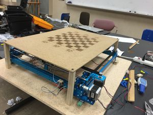
The purpose of this project is to create an automated chessboard, displaying moves made by users playing chess. The web application server will be hosted on a Beaglebone Black. Users log in and play a chess game hosted using Node.js. As moves are made on the web app,the pieces will be physically moved on the chessboard.
Objectives & Introduction
Show list of your objectives. This section includes the high level details of your project. You can write about the various sensors or peripherals you used to get your project completed.
Team Members & Responsibilities
- Yaron Alexandrovich
- Case Design, XY Plotter driver on SJOne Board, FreeRTOS Environment
- Emil Kurian
- Case Design, XY Plotter driver on SJOne Board, FreeRTOS Environment
- Gerard Ramos
- Web Server, Case Design, Electromagnet, Chess Pieces
- Fred Sun
- Web Server, Case Design, Electromagnet, Chess Pieces
Schedule
| Week | Start Date | End Date | Task | Status |
|---|---|---|---|---|
| 1 | 3/27/2015 | 4/10/2015 | Finish building XY Plotter | Completed |
| 2 | 4/12/2015 | 4/26/2015 | Build casing and chessboard | In Progress |
| 3 | 4/12/2015 | 4/19/2015 | Build/Control Electromagnet | In Progress |
| 4 | 4/12/2015 | 4/15/2015 | Find/Buy appropriate magnets | Completed |
| 5 | 4/12/2015 | 4/19/2015 | Write drivers for XY-Plotter | Completed |
| 6 | 4/12/2015 | 4/19/2015 | Design web application GUI (Front-end) | Completed |
| 7 | 4/12/2015 | 4/26/2015 | Host Web Server on Campus | Completed |
| 8 | 4/19/2015 | 4/26/2015 | 3D print chess pieces + attach magnets to pieces | In Progress |
| 9 | 4/19/2015 | 5/3/2015 | Develop Web Server Back-end | Completed |
| 10 | 4/26/2015 | 5/3/2015 | Write functions for plotter to move chess pieces | In Progress |
| 11 | 5/3/2015 | 5/10/2015 | Setup communication protocol between SJOne and Web Server | In Progress |
| 12 | 5/3/2015 | 5/17/2015 | FreeRTOS Environment | In Progress |
| 13 | 5/15/2015 | 5/23/2015 | Debug, Debug, Debug | In Progress |
Parts List & Cost
Give a simple list of the cost of your project broken down by components. Do not write long stories here.
| # | Item | Cost | Quantity | Total Cost |
|---|---|---|---|---|
| 1 | XY Plotter | $300 | 1 | $300 |
| 2 | Wood | $10 | 3 | $30 |
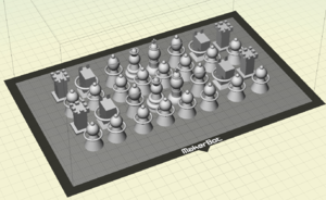
Computer Aided Design Chess Pieces
Electromagnet
Hardware Interface
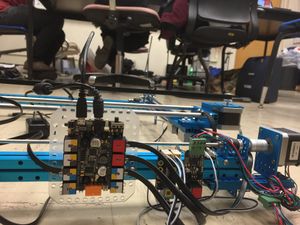
The chess game is hosted on a Beaglebone Black (BBB). The BBB is a open-source hardware single-board computer that runs an embedded Linux. The server back-end is powered by Node.JS, and ran as a local host such that any computer device can connect to it and play the game. As plays are made on the chess game, the changes in piece position are processed, and a string is transmitted over UART to the SJOne board. The SJOne interprets the string, and translates these to physical moves. By commanding the stepper motors and electromagnet, it moves chess pieces to reflect the changes made in game.
Software Design
Show your software design. For example, if you are designing an MP3 Player, show the tasks that you are using, and what they are doing at a high level. Do not show the details of the code. For example, do not show exact code, but you may show psuedocode and fragments of code. Keep in mind that you are showing DESIGN of your software, not the inner workings of it.
Our software was a two pronged approach: a website built from nodeJS and hosted on the BBB as well as a stepper motor control system implemented on the SJ1.
Implementation
This section includes implementation, but again, not the details, just the high level. For example, you can list the steps it takes to communicate over a sensor, or the steps needed to write a page of memory onto SPI Flash. You can include sub-sections for each of your component implementation.
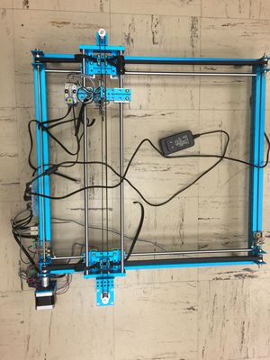
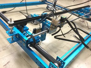
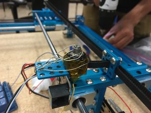
The chess board was created from an XY Plotter. The electromagnet was attached to the plotter, and would move under the chess board in order to pick up and move pieces. The Chess board itself was made from wood, and laser cut to our specification based on the usable size of the XY Plotter.
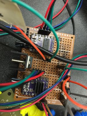
In order to use the stepper motors, 2 processes needed to occur. The first was setting the stepper motor driver. Our Drivers were the MD20B stepper motor drivers from Pololu, based on the DRV8825 IC from TI. In order to use these drivers, we had to manually set the step size and attach the power source we would be using. The logic was taken from the SJone, and the external power came from a 12V, 2A power supply.
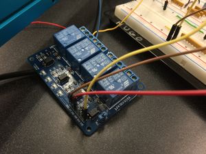
After, we worked on the electromagnet. The magnet was handmade with the turns being wound by the team and power coming from an external 12-24V, 5A power source.
Our game was hosed on the BBB, but our plotter was controlled by the SJone. In order to figure out where to move the pieces, a UART driver had to be created in order to pass data from the BBB to the SJone. The UART driver was interrupt based and would take in 5 characters at a time. These characters would then be deciphered and used to figure out the new chess piece locations.
Based on the location data for the pieces, the SJone would then engage the stepper motors and move them to the desired locations. This feat was accomplished by creating a software driver for the XY Plotter on the SJone board itself. The software driver was then used to create various move functions to be carried out based on the data coming in from the BBB.
Our Chess Pieces were 3d Printed and then modified for our use. The Modification was to add in a small magnet inside the chess piece and then weight the piece with a nut and washer on the bottom. These modifications allowed for the pieces to be grabbed by our electromagnet while staying stable and not getting attached to one another.
Testing & Technical Challenges
Describe the challenges of your project. What advise would you give yourself or someone else if your project can be started from scratch again? Make a smooth transition to testing section and described what it took to test your project.
Include sub-sections that list out a problem and solution, such as:
Test #1
Electromagnet
The electromagnet needs to be strong enough to grip a piece directly above it, without gripping any neighboring pieces. Initially, we attempted to make the chess pieces magnetic. First we tried neodymium magnets, however these magnets were far too powerful. We tried increasingly smaller magnets, but even our weakest magnets caused pieces to grip each other. We concluded that the pieces should NOT include permanent magnets.
My Issue #1
Stepper motor drivers are very easy to fry.
As current flows into a stepper motor, it stores this energy in magnetic fields. The reverse is true. That is, when current is no longer supplied to the motor, the magnetic field collapses creating current, known as back EMF. The stepper motor drivers contain circuitry to protect itself from this back EMF. However, adjusting the current setting or unplugging the stepper motor driver while engaged WILL damage the driver.
We fried two sets of stepper motor drivers.
My Issue #2
One of the other issues we encountered was with safety regarding the electromagnet, mainly due to heat, one of the things we wanted to calculate was how much current to run through the electromagnet in order to start moving pieces. As we were doing our test, the way that the electromagnet moved under the board scraped little pieces of wood on it. After a couple of minutes of testing we noticed smoke coming from the bottom of the board, at first we thought it was the electromagnet heating up the board way too much but actually the issue was the the little pieces of wood was going on the electromagnet, and due to the high amount of heat this caused the wooden dust to burn. After noticing this fire hazard we decided to not use the electromagnet anymore because it wasn't worth the risk if anything catching on fire.
My Issue #3
The XY Plotter Stepper Motors were a little bit harder to use than expected, in the beginning we tried using their software but we ended up not liking the way they had it set up. Since the plotter was mainly controlled by stepper motors and we had enough experience with them we decided to just bypass their software and hardware drivers and just create our own. However one of the main issues was callibration and getting the bump switches to read properly, for some reason we couldn't get readings from our bump switches and the callibration for the plotter was only set for their software, so we had a lot of trouble getting the stepper motors to move along their grid.
Conclusion
Conclude your project here. You can recap your testing and problems. You should address the "so what" part here to indicate what you ultimately learnt from this project. How has this project increased your knowledge?
We set out to create a Chess Board that could move the pieces by itself based on a game being played online. Instead, we created a potential fire hazard. After realizing that we created a potential fire hazard, we changed around a few things and instead created what was originally intended, a Wizard's Chess System. The Wizard's Chess possesses the ability to engage multiple players and move the pieces across the board via magnets underneath, suggesting to an errant watcher that the board indeed is magical.
As mentioned before, there were a few hiccups like the potential fire hazard. Testing and debugging the chess board was its own task because of the drivers we created from scratch. The motor drivers weren't as robust as we would have liked, wasting time and resources just to replace the driver over simple issues. Not to mention the testing that had to be done each phase such as how much power was going into each component or making sure that all the hardware was aligned in order to ensure that the precision we needed was there to play the game.
Overall, it would seem that a lot of effort went into creating a "over-the-top" version of a simple game. However, the chessboard we created draws from the various lessons learned though this class the and years we have been in engineering. A UART driver was implemented between two microcontrollers and ensured that the transmissions were read and properly processed. A driver was created for the XY Plotter from scratch, with all locations being mapped and programmed accordingly. An electromagnet was created, and though ultimately scrapped, it was successful in its intended purpose. FreeRTOS was used to prioritize the tasks of our board in order to ensure that all necessary functions were carried out properly and efficiently. By working on this project, the gap between knowledge attained in class and the actual implementation of these lessons was bridged.
Project Video
Upload a video of your project and post the link here.
Project Source Code
References
Acknowledgement
Special thanks to Hugo Quiroz. He provided mechanical knowledge, access to laboratory and equipment, and dedication to our project. Thanks for the measures, cuts, materials, and laser cutter to etch our chess board.
Special thanks to Professor Peter Reischl. He went out of his way to educate us on constructing the electromagnet. Thanks for going out of your way to provide the knowledge and verification to construct our electromagnet.
References Used
List any references used in project.
Appendix
You can list the references you used.
