Difference between revisions of "S15: Patient Buddy System (PBS)"
Proj user7 (talk | contribs) (→Design & Implementation) |
Proj user7 (talk | contribs) (→Project Video) |
||
| (118 intermediate revisions by the same user not shown) | |||
| Line 1: | Line 1: | ||
| − | === | + | == Patient Buddy System == |
| − | |||
| − | |||
| − | |||
| − | |||
| − | |||
| − | |||
| − | |||
| − | |||
| − | |||
| − | |||
| − | + | ||
| + | [[File: S15_PBS_FinalPrototype.JPG|400px|thumb|center|Final Prototype]] | ||
== Abstract == | == Abstract == | ||
| Line 83: | Line 74: | ||
== Parts List & Cost == | == Parts List & Cost == | ||
| − | + | ||
| − | + | ||
| − | + | {| class="wikitable" | |
| + | |- | ||
| + | ! scope="col"| Item# | ||
| + | ! scope="col"| Part | ||
| + | ! scope="col"| Vendor | ||
| + | ! scope="col"| Vendor P/N | ||
| + | ! scope="col"| Cost | ||
| + | ! scope="col"| Link | ||
| + | |- | ||
| + | ! scope="row"| 1 | ||
| + | | SJ One Board | ||
| + | | Preet | ||
| + | | n/a | ||
| + | | 79.99$ | ||
| + | | http://www.socialledge.com/sjsu/index.php?title=SJ_One_Board | ||
| + | |- | ||
| + | ! scope="row"| 2 | ||
| + | | Pulse Sensor | ||
| + | | Sparkfun | ||
| + | | SEN-11574 | ||
| + | | 24.95$ | ||
| + | | https://www.sparkfun.com/products/11574 | ||
| + | |- | ||
| + | ! scope="row"| 3 | ||
| + | | Electric Imp | ||
| + | | Sparkfun | ||
| + | | WRL-11395 | ||
| + | | 29.95$ | ||
| + | | https://www.sparkfun.com/products/11395 | ||
| + | |- | ||
| + | ! scope="row"| 4 | ||
| + | | Electric Imp Breakout Board | ||
| + | | Sparkfun | ||
| + | | BoB-12886 | ||
| + | | 12.95$ | ||
| + | | https://www.sparkfun.com/products/12886 | ||
| + | |- | ||
| + | ! scope="row"| 5 | ||
| + | | Temperature Sensor-TMP36 | ||
| + | | Sparkfun | ||
| + | | SEN-10988 | ||
| + | | 01.50$ | ||
| + | | https://www.sparkfun.com/products/10988 | ||
| + | |- | ||
| + | |} | ||
| + | *Total Cost: 153.79$ | ||
== Design & Implementation == | == Design & Implementation == | ||
| − | [[File: | + | [[File:S15_PBS_SystemOverview2.jpg|600px]] |
| + | |||
=== Hardware Design === | === Hardware Design === | ||
| − | |||
| − | [[File: | + | |
| + | [[File:S15_PBS_HardwareSchematicUpdate.PNG]] | ||
| + | |||
| + | =====Main Hardware Required===== | ||
| + | *SJ One Board: Custom made for CMPE 244 class applications. | ||
| + | *Pulse Sensor: Uses plethysmography to get the pulse reading | ||
| + | *MMA8452: Acceleration sensor to get the 3-Axes acceleration | ||
| + | *Electric Imp: Wifi module used to send on-board data to the server | ||
| + | *TMP36: Temperature sensor used to get surface temperature | ||
| + | |||
| + | [[File:S15_PBS_HardwareComponents.PNG|700px|thumb|center|Hardware Components Required]] | ||
=== Hardware Interface === | === Hardware Interface === | ||
| − | + | ||
*Pulse sensor: | *Pulse sensor: | ||
**Sends the raw photoplethysmograph signal to the on-board ADC and the signal is sampled every 2ms. | **Sends the raw photoplethysmograph signal to the on-board ADC and the signal is sampled every 2ms. | ||
*Accelerometer sensor: | *Accelerometer sensor: | ||
| − | **On-board accelerometer sensor is interfaced via the I2C bus to get the 3- | + | **On-board accelerometer sensor is interfaced via the I2C bus to get the 3-Axes acceleration. |
*Temperature sensor: | *Temperature sensor: | ||
| − | **External temperature sensor, | + | **External temperature sensor, TMP36, is interfaced via the analog port to get on-body temperature readings. |
*Electric Imp: | *Electric Imp: | ||
**Collected data is sent to the server via Electric Imp. UART bus is used for communication between the board and Electric Imp. | **Collected data is sent to the server via Electric Imp. UART bus is used for communication between the board and Electric Imp. | ||
=== Software Design === | === Software Design === | ||
| − | |||
| − | * | + | |
| − | + | *Firmware of the SJ One Board is designed using FreeRTOS. C++ language is used to write the firmware. The drivers provided by the SJ One Board manufacturer are used for low level application. Each task is assigned to collect a measurement, process an algorithm on it and compute the result. To maintain the high accuracy sampling frequency of the pulse sensor, the RIT- repetitive timers, interrupt service routine and binary semaphore are used. To maintain the sampling frequency of the accelerometer and the temperature sensor vTaskDelay is used. Since the clock cycles spent on the tasks are low, using the vTaskDelay was accurate enough to get a reasonably constant sampling frequency of the accelerometer and the temperature sensors. | |
| − | * | + | |
| − | ** | + | =====ALGORITHMS:===== |
| − | **Determine the critical | + | |
| − | + | =====1. Heart Rate calculation:===== | |
| + | *The heart rate (bpm) is calculated by sensing the photoplethysmograph signal from the Pulse Sensor. By using the adc0_get_reading() function, we are able to read the analog signal from the sensor. Since the analog signal we were getting was noisy, we used a standard median filter with window size of 3 to eliminate the noise. By comparing the three consecutive analog value, we are able to find the peak of the signal. By calculating the average time between the 10 consecutive peaks, the inter-beat interval (IBI) is calculated, from which the heart rate is determined. | ||
| + | [[File:S15_PBS_Dichrotic_Notch.jpeg|120px|thumb|left|Dichrotic notch]] | ||
| + | *Algorithm Pseudocode: | ||
| + | **Find the peak of the signal, time_of_last_peak = current time. | ||
| + | **Find the next peak, time_of_next_peak = current time | ||
| + | **Interval = time_of_last_peak - time_of_next_peak. | ||
| + | **If interval is < ( Interbeat_Beat_Interval*(3/5) ). Ignore it- this helps to eliminate the dicrotic notch. | ||
| + | **Calculate the Interbeat_Beat_Interval which is average of ten intervals | ||
| + | **Heart rate = 1 min/Interbeat_Beat_Interval and loop back to the: find first peak......... | ||
| + | |||
| + | =====2. Step Count Algorithm:===== | ||
| + | *The step count is calculated using the on-board accelerometer. Initial threshold for the step count is calculated based on the R&D, as mentioned in the implementation part. | ||
| + | *Pseudocode: | ||
| + | **Initialize the dynamic Threshold ( refer Analyzing the sensor signal section) | ||
| + | **Calculate the energy, energy = sqrt(x*x + y*y + z*z) | ||
| + | **Find the peak and the trough, amp = peak - trough | ||
| + | **if((amp > dynamic threshold*0.5)&&(current_time-last_step_time > 0.4s)) {step_count++} //Calculate the amplitude | ||
| + | **NOTE: 0.4 sec was picked based on the assumption, possible maximum walking speed is 150 steps/min | ||
| + | **Calculate the harmonic average of the past 5 amplitudes | ||
| + | **Update the dynamic threshold = harmonic average and then loop back to energy calculation. | ||
| + | |||
| + | =====3. Patient Orientation:===== | ||
| + | *Pseudocode: | ||
| + | **Read the z acceleration | ||
| + | **If z>700 for 10sec, then patient position = lying down | ||
| + | **If z<700 for 10sec, then patient position = standing. | ||
| + | |||
| + | =====4. Critical Conditions:===== | ||
| + | *Determine if the heart rate is critical | ||
| + | *Determine if temperature is normal range | ||
| + | *Determine if emergency is requested by the patient | ||
| + | |||
| + | |||
| + | =====CLOUD AND THE APP COMMUNICATION===== | ||
| + | The cloud provided by the Electric Imp is used to pass the data to the mobile app. The Electric Imp consists of two components: 1) The device and 2) The agent-the electric imp cloud server. The device is the actual hardware which sends the data to the agent through WiFi and the mobile app will pull the data from the agent (server). Squirrel language is used to write the software for the agent and the device. The android mobile app is created in Java. | ||
| + | |||
| + | *Logic: | ||
| + | **1). Device: | ||
| + | ***Receive data from the SJ ONE Board through UART. | ||
| + | ***Send the data to the agent- Example code: agent.send("HR", HR); | ||
| + | **2). Agent: | ||
| + | ***Receive the data from the device | ||
| + | ***Store them in the server. | ||
| + | ***On http request data is sent back using the following code:response.send(200,format("heart=%d,temprature=%d,poistion=%d,step=%d,emergency=%d",HRval,tempval,poval,stepval,eoval)); | ||
=== Implementation === | === Implementation === | ||
| − | + | =====Analyzing the Sensor Signals===== | |
| + | =====1. Heart Rate: ===== | ||
| + | *Photoplethysmograph signal of the pulse sensor is obtained by reading the analog signal of the pulse sensor, as previously mentioned. This analog signal is read every 2ms and transferred from the SJ One Board to the computer through UART. The data is then logged into the computer for ten minutes using the Terminal v1.9b software (https://goo.gl/yJZCC). | ||
| + | *This data is imported to Matlab and then plotted as shown in the figure below: | ||
| + | [[File: S15_PBS_HeartRate_PreFilter.jpg|400px|thumb|center|PreFiltered Readings]] | ||
| + | *According to the figure the data obtained contained some noise. Hence, different filters were tried and tested to eliminate the noise. Finally the Standard Median Filter with a window size of 3 was found as the optimal filter with low clock cycles. | ||
| + | *This figure below shows the filtered signal, after the noise was removed: | ||
| + | [[File: S15_PBS_HeartRate_PostFilter.jpg|400px|thumb|center|PostFiltered Readings]] | ||
| + | *This filter is implemented on the SJ ONE Board and the filtered signal is fed into the function which computes the heart rate algorithm. | ||
| + | |||
| + | =====2. Step Count:===== | ||
| + | *Read the X,Y,Z acceleration of on board sensor and save the data on the SD card using Storage::append("1:myfile.txt",data,28,0); | ||
| + | *By using the setup as shown in the picture, acceleration of x,y,z for 50 steps was collected on the SD card | ||
| + | *Read the data from the SD card and transfer the data to the computer through UART | ||
| + | *Data was loaded in MatLab and step count algorithm was implemented in Matlab first and this algorithm was verified using this data. | ||
| + | *The figure below shows energy vs time plot while walking: energy = (x*x +y*y +z*z) | ||
| + | [[File: S15_PBS_Step3.jpg|500px|thumb|center|Steps.]] | ||
| + | *This matlab code was ported to the SJ One board. | ||
| + | |||
| + | ====Firmware Implementation==== | ||
[[File:S15_PBS_SoftwareImplementation.PNG]] | [[File:S15_PBS_SoftwareImplementation.PNG]] | ||
| + | |||
| + | |||
| + | ====Android Implementation==== | ||
| + | |||
| + | *Step 1 - Setup Java Development Kit (JDK) | ||
| + | *Step 2 - Setup Android SDK | ||
| + | *Step 3 - Setup Eclipse/Studio IDE | ||
| + | *Step 4 - Setup Android Development Tools (ADT) Plugin | ||
| + | *Step 5 - Create Android Virtual Device | ||
| + | *Step 6 - Program the application in Java | ||
| + | *Step 7 - Run the APK file on the android device | ||
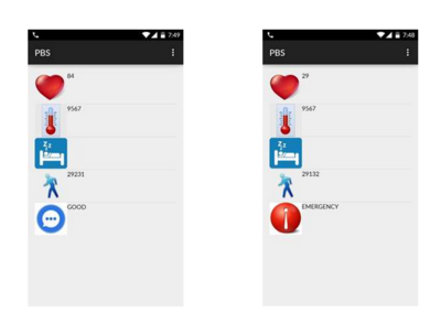
| + | [[File:S15_PBS_AndroidApp.PNG|400px|thumb|center|PBS App]] | ||
== Testing & Technical Challenges == | == Testing & Technical Challenges == | ||
| − | + | ||
| − | + | ||
| + | The main modules for the system were tested on different subjects to check for subject to subject consistency. These tests include: | ||
| + | *STEP COUNT: | ||
| + | **Step count was tested on two subjects, Subject 1 and Subject 2, and in two different modes, fast and normal mode. On each test 100 steps were made. The table below show the results: | ||
| + | |||
| + | |||
| + | [[File: S15_PBS_StepTestResults.jpg|400px|thumb|center|Results]] | ||
| + | |||
| + | *End to End Communication: | ||
| + | **Made sure that data was periodically updated on the app as it was collected, and there was no delay or loss of connectivity. | ||
Include sub-sections that list out a problem and solution, such as: | Include sub-sections that list out a problem and solution, such as: | ||
| − | === | + | ====Issues Faced==== |
| − | + | *Issue #1: | |
| − | * | + | **Issue: Initially, the heart rate algorithm was not working as expected. It would read some junk data values and the values did not align with the on body placement of the sensor. To rule out the problem, the adc value of the pulse sensor was logged and plotted. In the plots, it was noticed that the signal had random sudden spikes(noise). As a result, the heart rate did not read the correct bpm values. |
| − | **Issue | + | **Solution: To remove the noise spikes from the signal, a standard median filter with window size 3 was implemented. |
| − | ** | + | *Issue #2: |
| + | **After integrating the electric Imp with the SJ ONE Board, the heart rate values computed were off again. To solve this issue, we logged and plotted the adc value again. When the Electric Imp was powered from the SJ One Board, periodic spikes were found. But when the Electric Imp was unplugged the signal was clean. From this, it was clear that the noise was coming from the Electric Imp. | ||
| + | **Solution: As a temporary solution, the Electric Imp and the SJ One Board were powered up with two different batteries. | ||
| + | *Issue #3: | ||
| + | **The pulse sensor was very sensitive to the environment light, because of which it gave random heart rate readings even when the sensor was off the body. | ||
| + | **Solution : We assume that the sensor will be on the body while in use. | ||
== Conclusion == | == Conclusion == | ||
| − | + | ||
| + | *Things we learned: | ||
| + | **System design and implementation from concept phase to testing phase | ||
| + | **Interfacing the sensors with the SJ One Eval Board and troubleshoot analog problems | ||
| + | **Implementing algorithms to get accurate data | ||
| + | **Using FreeRTOS to implement firmware design concept | ||
| + | **Using Electric Imp to send data to server in real time | ||
| + | **How to obtain data on android app | ||
| + | **Group work! | ||
| + | *Things we could have done different: | ||
| + | **The heart rate recorded from the PBS could have been compared to a gold standard to validate the algorithm | ||
| + | **More test conditions could have been implemented to see when the system fails and if it gives any false positives | ||
| + | **Rebuild the RTOS task system to optimize the tasks | ||
| + | *Future work: | ||
| + | **Make the prototype smaller and turn it into a wearable device | ||
| + | **Gel electrodes could be interfaced with the system to get ECG recordings | ||
| + | **Add on a feature in which the doctor can send or call patient when the patient requests for emergency | ||
| + | **Improve the app with a better GUI | ||
| + | **Track the activity of the patient and monitor its physiological data over time | ||
=== Project Video === | === Project Video === | ||
| − | + | https://www.youtube.com/watch?v=nBGfwDIN63E&feature=youtu.be&app=desktop | |
=== Project Source Code === | === Project Source Code === | ||
| Line 148: | Line 300: | ||
== References == | == References == | ||
=== Acknowledgement === | === Acknowledgement === | ||
| − | + | Thanks to Preet and all the ISAs for their help in the project! | |
=== References Used === | === References Used === | ||
| − | + | *http://www.computer.org/csdl/proceedings/icisa/2013/0602/00/06579332.pdf | |
| + | *http://pulsesensor.com/pages/pulse-sensor-amped-arduino-v1dot1 | ||
=== Appendix === | === Appendix === | ||
You can list the references you used. | You can list the references you used. | ||
Latest revision as of 09:17, 25 May 2015
Contents
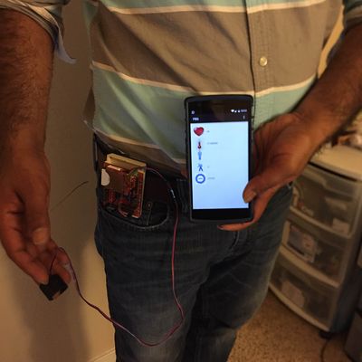
Patient Buddy System
Abstract
A system to enable the doctor or caregivers to remotely detect the physiologic measurements of multiple patients and receive alerts if patients’ conditions get critical or if the patient seeks emergency help. The system measures heartbeat, body temperature, position (sleeping or standing) and activity of the day (step count) continuously. The doctor or caregiver can monitor these measurements and receive alerts in their mobile app.
Objectives & Introduction
- Monitor physiologic measurements of the patients: heartbeat, temperature, patient position: sleeping or standing, patient activity: step count
- Allows the doctor/caregiver to monitor physiologic data for multiple patients.
- Determine if the patient’s physiological conditions are critical.
- Automatically alert the doctor/caregiver of the patient’s conditions if critical conditions are reached.
- Allow the patient to request for emergency help.
Team Members & Responsibilities
- Avinash Closepet Suresh
- Orientation algorithm development and implementation
- Girish Bangalore Ramesh
- Board to server communication implementation
- Thiruparan Balachandran
- Step count algorithm development, implementation and system integration
- Nimmi Bhatt
- Heart rate algorithm and implementation
- All of us:
- Collectively worked on end to end system testing and integrating data into an android app
Schedule
| Week# | Date | Task | Actual |
|---|---|---|---|
| 1 | 4/14/2015 | Order materials, ElectricImp exploration, Patient Position | Completed ordering materials |
| 2 | 4/21/2015 | Develop position details about the subject's orientation via the accelerometer, test different algorithm methods and store the data in Flash. | Completed getting the position details and developing a basic algorithm; Attempts to modify the algorithm are in progress. |
| 3 | 4/28/2015 | End to End Communication: Getting the data from the sensor and displaying it on the app's page. | Completed sending data via electric imp and reading it on the server on other side. |
| 4 | 5/05/2015 | Add other sensors to the system (temperature and heart rate) and work on doctor to patient communication and implement some emergency feature. | Completed integrating the heart rate sensor. The ADC collects the raw heart rate and runs the data through a heart rate algorithm. The algorithm will measure critical levels. |
| 5 | 5/12/2015 | Improve app and work on data analysis on the app's side to make the data look meaningful and interesting. | Completed heart rate algorithm and implemented DSP to get a cleaner heart rate. Completed processing accelerometer data to determine the footsteps and orientation. |
| 6 | 5/19/2015 | Improve and implement the android app and test the entire system from end to end. | Planned |
| 7 | 5/22/2015 | Demo! | Planned |
Parts List & Cost
| Item# | Part | Vendor | Vendor P/N | Cost | Link |
|---|---|---|---|---|---|
| 1 | SJ One Board | Preet | n/a | 79.99$ | http://www.socialledge.com/sjsu/index.php?title=SJ_One_Board |
| 2 | Pulse Sensor | Sparkfun | SEN-11574 | 24.95$ | https://www.sparkfun.com/products/11574 |
| 3 | Electric Imp | Sparkfun | WRL-11395 | 29.95$ | https://www.sparkfun.com/products/11395 |
| 4 | Electric Imp Breakout Board | Sparkfun | BoB-12886 | 12.95$ | https://www.sparkfun.com/products/12886 |
| 5 | Temperature Sensor-TMP36 | Sparkfun | SEN-10988 | 01.50$ | https://www.sparkfun.com/products/10988 |
- Total Cost: 153.79$
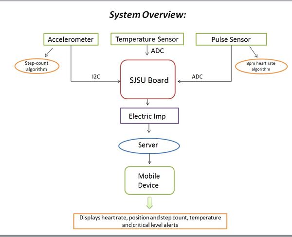
Design & Implementation
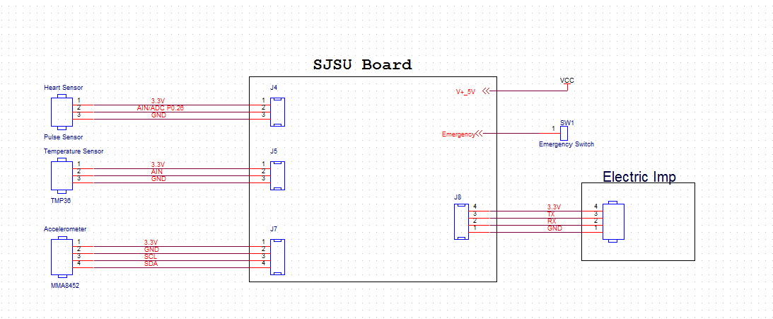
Hardware Design
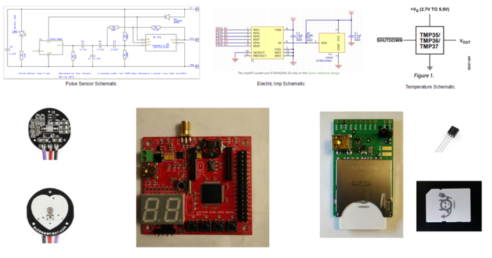
Main Hardware Required
- SJ One Board: Custom made for CMPE 244 class applications.
- Pulse Sensor: Uses plethysmography to get the pulse reading
- MMA8452: Acceleration sensor to get the 3-Axes acceleration
- Electric Imp: Wifi module used to send on-board data to the server
- TMP36: Temperature sensor used to get surface temperature
Hardware Interface
- Pulse sensor:
- Sends the raw photoplethysmograph signal to the on-board ADC and the signal is sampled every 2ms.
- Accelerometer sensor:
- On-board accelerometer sensor is interfaced via the I2C bus to get the 3-Axes acceleration.
- Temperature sensor:
- External temperature sensor, TMP36, is interfaced via the analog port to get on-body temperature readings.
- Electric Imp:
- Collected data is sent to the server via Electric Imp. UART bus is used for communication between the board and Electric Imp.
Software Design
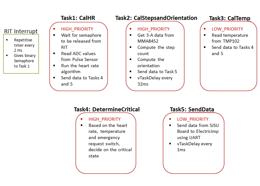
- Firmware of the SJ One Board is designed using FreeRTOS. C++ language is used to write the firmware. The drivers provided by the SJ One Board manufacturer are used for low level application. Each task is assigned to collect a measurement, process an algorithm on it and compute the result. To maintain the high accuracy sampling frequency of the pulse sensor, the RIT- repetitive timers, interrupt service routine and binary semaphore are used. To maintain the sampling frequency of the accelerometer and the temperature sensor vTaskDelay is used. Since the clock cycles spent on the tasks are low, using the vTaskDelay was accurate enough to get a reasonably constant sampling frequency of the accelerometer and the temperature sensors.
ALGORITHMS:
1. Heart Rate calculation:
- The heart rate (bpm) is calculated by sensing the photoplethysmograph signal from the Pulse Sensor. By using the adc0_get_reading() function, we are able to read the analog signal from the sensor. Since the analog signal we were getting was noisy, we used a standard median filter with window size of 3 to eliminate the noise. By comparing the three consecutive analog value, we are able to find the peak of the signal. By calculating the average time between the 10 consecutive peaks, the inter-beat interval (IBI) is calculated, from which the heart rate is determined.
- Algorithm Pseudocode:
- Find the peak of the signal, time_of_last_peak = current time.
- Find the next peak, time_of_next_peak = current time
- Interval = time_of_last_peak - time_of_next_peak.
- If interval is < ( Interbeat_Beat_Interval*(3/5) ). Ignore it- this helps to eliminate the dicrotic notch.
- Calculate the Interbeat_Beat_Interval which is average of ten intervals
- Heart rate = 1 min/Interbeat_Beat_Interval and loop back to the: find first peak.........
2. Step Count Algorithm:
- The step count is calculated using the on-board accelerometer. Initial threshold for the step count is calculated based on the R&D, as mentioned in the implementation part.
- Pseudocode:
- Initialize the dynamic Threshold ( refer Analyzing the sensor signal section)
- Calculate the energy, energy = sqrt(x*x + y*y + z*z)
- Find the peak and the trough, amp = peak - trough
- if((amp > dynamic threshold*0.5)&&(current_time-last_step_time > 0.4s)) {step_count++} //Calculate the amplitude
- NOTE: 0.4 sec was picked based on the assumption, possible maximum walking speed is 150 steps/min
- Calculate the harmonic average of the past 5 amplitudes
- Update the dynamic threshold = harmonic average and then loop back to energy calculation.
3. Patient Orientation:
- Pseudocode:
- Read the z acceleration
- If z>700 for 10sec, then patient position = lying down
- If z<700 for 10sec, then patient position = standing.
4. Critical Conditions:
- Determine if the heart rate is critical
- Determine if temperature is normal range
- Determine if emergency is requested by the patient
CLOUD AND THE APP COMMUNICATION
The cloud provided by the Electric Imp is used to pass the data to the mobile app. The Electric Imp consists of two components: 1) The device and 2) The agent-the electric imp cloud server. The device is the actual hardware which sends the data to the agent through WiFi and the mobile app will pull the data from the agent (server). Squirrel language is used to write the software for the agent and the device. The android mobile app is created in Java.
- Logic:
- 1). Device:
- Receive data from the SJ ONE Board through UART.
- Send the data to the agent- Example code: agent.send("HR", HR);
- 2). Agent:
- Receive the data from the device
- Store them in the server.
- On http request data is sent back using the following code:response.send(200,format("heart=%d,temprature=%d,poistion=%d,step=%d,emergency=%d",HRval,tempval,poval,stepval,eoval));
- 1). Device:
Implementation
Analyzing the Sensor Signals
1. Heart Rate:
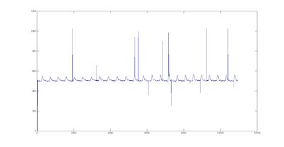
- Photoplethysmograph signal of the pulse sensor is obtained by reading the analog signal of the pulse sensor, as previously mentioned. This analog signal is read every 2ms and transferred from the SJ One Board to the computer through UART. The data is then logged into the computer for ten minutes using the Terminal v1.9b software (https://goo.gl/yJZCC).
- This data is imported to Matlab and then plotted as shown in the figure below:
- According to the figure the data obtained contained some noise. Hence, different filters were tried and tested to eliminate the noise. Finally the Standard Median Filter with a window size of 3 was found as the optimal filter with low clock cycles.
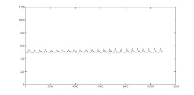
- This figure below shows the filtered signal, after the noise was removed:
- This filter is implemented on the SJ ONE Board and the filtered signal is fed into the function which computes the heart rate algorithm.
2. Step Count:
- Read the X,Y,Z acceleration of on board sensor and save the data on the SD card using Storage::append("1:myfile.txt",data,28,0);
- By using the setup as shown in the picture, acceleration of x,y,z for 50 steps was collected on the SD card
- Read the data from the SD card and transfer the data to the computer through UART
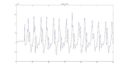
- Data was loaded in MatLab and step count algorithm was implemented in Matlab first and this algorithm was verified using this data.
- The figure below shows energy vs time plot while walking: energy = (x*x +y*y +z*z)
- This matlab code was ported to the SJ One board.
Firmware Implementation
Android Implementation
- Step 1 - Setup Java Development Kit (JDK)
- Step 2 - Setup Android SDK
- Step 3 - Setup Eclipse/Studio IDE
- Step 4 - Setup Android Development Tools (ADT) Plugin
- Step 5 - Create Android Virtual Device
- Step 6 - Program the application in Java
- Step 7 - Run the APK file on the android device
Testing & Technical Challenges
The main modules for the system were tested on different subjects to check for subject to subject consistency. These tests include:
- STEP COUNT:
- Step count was tested on two subjects, Subject 1 and Subject 2, and in two different modes, fast and normal mode. On each test 100 steps were made. The table below show the results:
- End to End Communication:
- Made sure that data was periodically updated on the app as it was collected, and there was no delay or loss of connectivity.
Include sub-sections that list out a problem and solution, such as:
Issues Faced
- Issue #1:
- Issue: Initially, the heart rate algorithm was not working as expected. It would read some junk data values and the values did not align with the on body placement of the sensor. To rule out the problem, the adc value of the pulse sensor was logged and plotted. In the plots, it was noticed that the signal had random sudden spikes(noise). As a result, the heart rate did not read the correct bpm values.
- Solution: To remove the noise spikes from the signal, a standard median filter with window size 3 was implemented.
- Issue #2:
- After integrating the electric Imp with the SJ ONE Board, the heart rate values computed were off again. To solve this issue, we logged and plotted the adc value again. When the Electric Imp was powered from the SJ One Board, periodic spikes were found. But when the Electric Imp was unplugged the signal was clean. From this, it was clear that the noise was coming from the Electric Imp.
- Solution: As a temporary solution, the Electric Imp and the SJ One Board were powered up with two different batteries.
- Issue #3:
- The pulse sensor was very sensitive to the environment light, because of which it gave random heart rate readings even when the sensor was off the body.
- Solution : We assume that the sensor will be on the body while in use.
Conclusion
- Things we learned:
- System design and implementation from concept phase to testing phase
- Interfacing the sensors with the SJ One Eval Board and troubleshoot analog problems
- Implementing algorithms to get accurate data
- Using FreeRTOS to implement firmware design concept
- Using Electric Imp to send data to server in real time
- How to obtain data on android app
- Group work!
- Things we could have done different:
- The heart rate recorded from the PBS could have been compared to a gold standard to validate the algorithm
- More test conditions could have been implemented to see when the system fails and if it gives any false positives
- Rebuild the RTOS task system to optimize the tasks
- Future work:
- Make the prototype smaller and turn it into a wearable device
- Gel electrodes could be interfaced with the system to get ECG recordings
- Add on a feature in which the doctor can send or call patient when the patient requests for emergency
- Improve the app with a better GUI
- Track the activity of the patient and monitor its physiological data over time
Project Video
https://www.youtube.com/watch?v=nBGfwDIN63E&feature=youtu.be&app=desktop
Project Source Code
References
Acknowledgement
Thanks to Preet and all the ISAs for their help in the project!
References Used
- http://www.computer.org/csdl/proceedings/icisa/2013/0602/00/06579332.pdf
- http://pulsesensor.com/pages/pulse-sensor-amped-arduino-v1dot1
Appendix
You can list the references you used.
