Difference between revisions of "S15: Hand Gesture Recognition using IR Sensors"
Proj user9 (talk | contribs) (→Parts List & Cost) |
Proj user9 (talk | contribs) (→Conclusion) |
||
| (79 intermediate revisions by the same user not shown) | |||
| Line 2: | Line 2: | ||
== Abstract == | == Abstract == | ||
| − | The aim of the project is to develop hand gesture recognition system using grid of IR proximity | + | <p style="text-indent: 1em; text-align: justify;"> |
| − | sensors. | + | The aim of the project is to develop hand gesture recognition system using grid of IR proximity sensors. Various hand gestures like swipe, pan etc. can be recognized. These gestures can be used to control different devices or can be used in various applications. The system will recognize different hand gestures based on the values received from IR proximity sensors. We have used Qt to develop the application to demonstrate the working of the project. |
| − | can be recognized. These gestures can be used to control different devices or can be used in various | + | </p> |
| − | applications.The system will recognize different hand gestures based on the IR proximity | ||
== Objectives & Introduction == | == Objectives & Introduction == | ||
| + | <p style="text-indent: 1em; text-align: justify;"> | ||
| + | We use various hand gestures in our day-to-day life to communicate while trying to explain someone something, direct them somewhere etc. It would be so cool if we could communicate with various applications running on the computers or different devices around us understand the hand gestures and give the expected output. | ||
| − | + | In order to achieve this, we are using a 3-by-3 grid of analog IR proximity sensors and connecting these sensors via multiplexers to the ADC pins on SJOne Board. As a hand is moved in front of the sensors, the sensor values would in a particular pattern enabling us to detect the gesture and instruct the application to perform the corresponding action. | |
| − | + | </p> | |
| − | |||
| − | |||
| − | |||
| − | |||
| − | |||
| − | |||
=== Team Members & Responsibilities === | === Team Members & Responsibilities === | ||
* Harita Parekh | * Harita Parekh | ||
| Line 29: | Line 24: | ||
== Schedule == | == Schedule == | ||
| − | |||
{| class="wikitable" | {| class="wikitable" | ||
| Line 54: | Line 48: | ||
| Read the data sheet for sensors and understand its working. Test multiplexers | | Read the data sheet for sensors and understand its working. Test multiplexers | ||
| Completed | | Completed | ||
| − | | align="center" |4/ | + | | align="center" |4/04/2015 |
|- | |- | ||
|- | |- | ||
| 3 | | 3 | ||
| − | | align="center" |4/ | + | | align="center" |4/05/2015 |
| align="center" |4/11/2015 | | align="center" |4/11/2015 | ||
| Interfacing of sensors, multiplexers and controller | | Interfacing of sensors, multiplexers and controller | ||
| Line 72: | Line 66: | ||
* Implement algorithm to recognize left-to-right movement | * Implement algorithm to recognize left-to-right movement | ||
| − | | | + | | Completed |
| − | | | + | | align="center" |4/25/2015 |
|- | |- | ||
|- | |- | ||
| Line 85: | Line 79: | ||
* Implement algorithm to recognize right-to-left movement | * Implement algorithm to recognize right-to-left movement | ||
| − | | | + | | Completed |
| − | | align="center" | | + | | align="center" |5/02/2015 |
|- | |- | ||
|- | |- | ||
| 6 | | 6 | ||
| align="center" |4/26/2015 | | align="center" |4/26/2015 | ||
| − | | align="center" |5/ | + | | align="center" |5/02/2015 |
| | | | ||
| − | |||
| − | |||
* Implement algorithm to recognize down-to-up movement | * Implement algorithm to recognize down-to-up movement | ||
| − | * Develop the application | + | * Develop the Qt application |
| − | | | + | | Completed |
| − | | align="center" | | + | | align="center" |5/09/2015 |
|- | |- | ||
|- | |- | ||
| 7 | | 7 | ||
| − | | align="center" |5/ | + | | align="center" |5/03/2015 |
| − | | align="center" |5/ | + | | align="center" |5/09/2015 |
| Testing and bug fixes | | Testing and bug fixes | ||
| − | | | + | | Completed |
| − | | align="center" | | + | | align="center" |5/15/2015 |
|- | |- | ||
|- | |- | ||
| Line 114: | Line 106: | ||
| align="center" |5/16/2015 | | align="center" |5/16/2015 | ||
| Testing and final touches | | Testing and final touches | ||
| − | | | + | | Completed |
| − | | align="center" | | + | | align="center" |5/22/2015 |
|- | |- | ||
|- | |- | ||
| 9 | | 9 | ||
| + | | align="center" |5/21/2015 | ||
| + | | align="center" |5/24/2015 | ||
| + | | Report Completion | ||
| + | | Completed | ||
| + | | align="center" |5/24/2015 | ||
| + | |- | ||
| + | |- | ||
| + | | 10 | ||
| align="center" |5/25/2015 | | align="center" |5/25/2015 | ||
| align="center" |5/25/2015 | | align="center" |5/25/2015 | ||
| Final demo | | Final demo | ||
| Scheduled | | Scheduled | ||
| − | | align="center" | | + | | align="center" |5/25/2015 |
|- | |- | ||
| − | |||
|} | |} | ||
| Line 137: | Line 136: | ||
! scope="col"| Total Price | ! scope="col"| Total Price | ||
|- | |- | ||
| − | + | ! align="justify" scope="row"| 1 | |
| − | | 1 | ||
| Sharp Distance Measuring Sensor Unit (GP2Y0A21YK0F) | | Sharp Distance Measuring Sensor Unit (GP2Y0A21YK0F) | ||
| align="center" |9 | | align="center" |9 | ||
| Line 144: | Line 142: | ||
| $134.55 | | $134.55 | ||
|- | |- | ||
| − | + | ! align="justify" scope="row"| 2 | |
| − | | 2 | ||
| STMicroelectronics Dual 4-Channel Analog Multiplexer/Demultiplexer (M74HC4052) | | STMicroelectronics Dual 4-Channel Analog Multiplexer/Demultiplexer (M74HC4052) | ||
| align="center" |3 | | align="center" |3 | ||
| − | | $ | + | | $0.56 |
| − | | $ | + | | $1.68 |
|- | |- | ||
| − | + | ! align="justify" scope="row"| 3 | |
| − | | 3 | ||
| SJ-One Board | | SJ-One Board | ||
| align="center" |1 | | align="center" |1 | ||
| Line 158: | Line 154: | ||
| $80 | | $80 | ||
|- | |- | ||
| + | ! align="justify" scope="row"| 4 | ||
| + | | USB-to-UART converter | ||
| + | | align="center" |1 | ||
| + | | $7 | ||
| + | | $7 | ||
| + | |- | ||
| + | ! align="left" colspan="4" | Total (excluding shipping and taxes) | ||
| + | | $223.23 | ||
|} | |} | ||
== Design & Implementation == | == Design & Implementation == | ||
| − | The | + | === Hardware Design === |
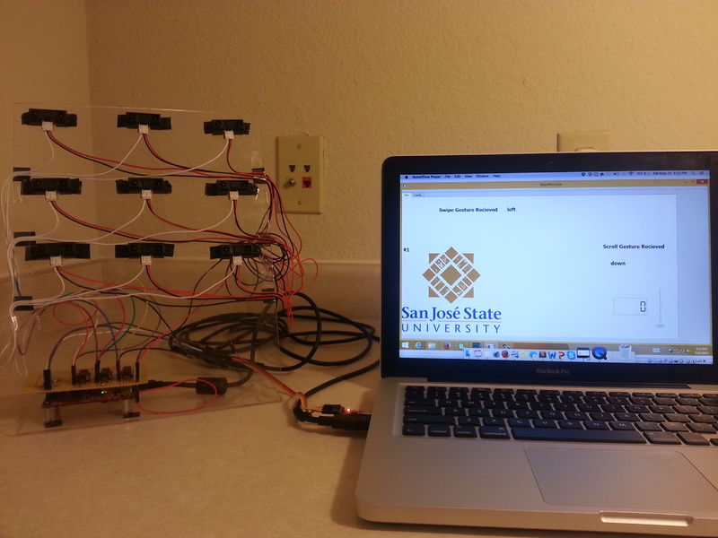
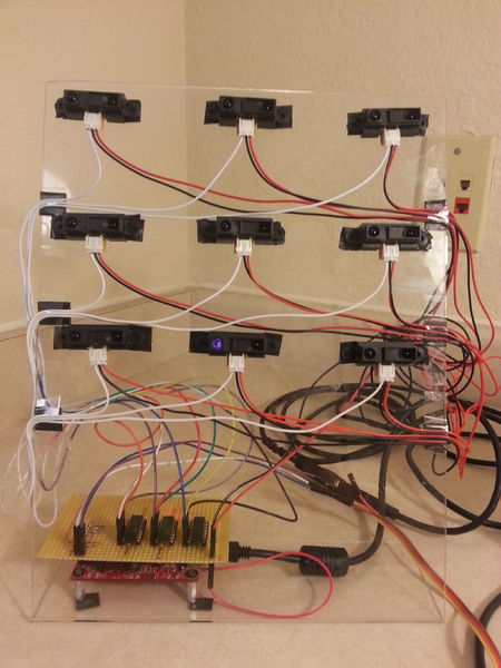
| + | The image shows the setup of the project.<br> | ||
| + | [[File:S15 244 Grp10 Ges system setup.jpg|800px|center]]<br> | ||
| + | <center>Figure 1: Setup of the project</center> | ||
| + | <br> | ||
| + | <table> | ||
| + | <tr valign="top"> | ||
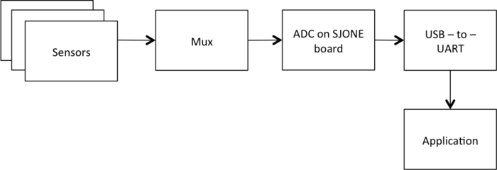
| + | <b><i>System Block Diagram:</i></b> | ||
| + | </tr> | ||
| + | <br> | ||
| + | <tr> | ||
| + | <td valign="top" align="center"> | ||
| + | [[File:S15 244 Grp10 Ges block diagram.png|700px|center]]<br> | ||
| + | <center>Figure 2: System Block Diagram</center> <br> | ||
| + | </td> | ||
| + | </tr> | ||
| − | === | + | <tr align="justify"> |
| − | + | <p style="text-indent: 1em; text-align: justify;"> | |
| + | The system consists of 9 IR proximity sensors, which are arranged in 3x3 grid. The output of the sensors is given to the Analog-to-Digital convertor on the SJOne Board to get the digital equivalent of the voltage given by the sensors. Since there are only 3 ADC channels exposed on the pins on the board, we cannot connect all the sensors directly to the board. For these we have used three multiplexers, which has 3 sensors each connected to its input. The output of the multiplexers is connected to ADC. SJOne board is connected to the laptop via UART-to-USB connection.</p> | ||
| + | </tr> | ||
| + | |||
| + | <tr> | ||
| + | <td valign="top" align="justify" width=950px> | ||
| + | <b><i>Proximity Sensor:</i></b> | ||
| + | <br> | ||
| + | <p style="text-indent: 1em; text-align: justify;"> | ||
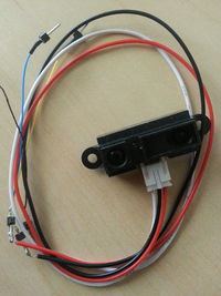
| + | This sensor by Sharp measures the distance from an obstacle by bouncing IR rays off the obstacle. This sensor can measure distances from 10 to 80 cms. The sensor returns an analog voltage corresponding to the distance from the obstacle. Depending on which sensor returns valid values, validations could be made and hand movement can be determined. The voltage returned by the sensor increases as the obstacle approaches the sensor. There is no external circuitry required for this sensor. The operating voltage recommended for this sensor is 4.5V to 5.5V.</p> | ||
| + | </td> | ||
| + | <td> | ||
| + | [[File:S15 244 G10 Ges sensor.jpg|200px]]<br> | ||
| + | <center>Figure 3: IR Proximity Sensor</center><br> | ||
| + | </td> | ||
| + | </tr> | ||
| + | |||
| + | <tr> | ||
| + | <td valign="top" align="justify" width=950px> | ||
| + | <b><i>Multiplexer:</i></b> | ||
| + | <br> | ||
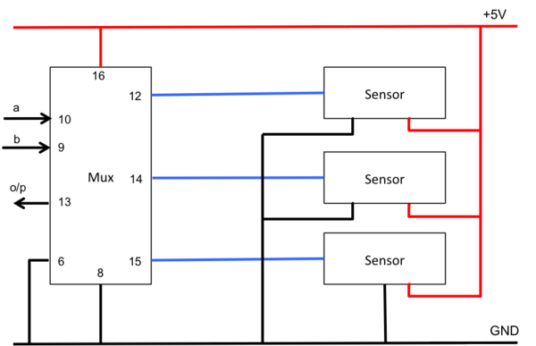
| + | <p style="text-indent: 1em; text-align: justify;"> | ||
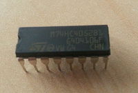
| + | The chip used in the project is M74HC4052 from STMicroelectronics. This is a dual 4-channel multiplexer/demultiplexer. Due to shortage of ADC pins to interface with the sensors, use of multiplexer is required. The multiplexer takes input from three sensors and enables only one of them at the output. The program logic decides which sensor’s output should be enabled at the multiplexer’s output. A and B control signals select one of the channel out of the four. The operating voltage for the multiplexer is 2 to 6V.</p> | ||
| + | </td> | ||
| + | <td> | ||
| + | [[File:S15 244 G10 Ges mux.jpg|200px]]<br> | ||
| + | <center>Figure 4: 4-Channel Dual Multiplexer</center><br> | ||
| + | </td> | ||
| + | </tr> | ||
| + | |||
| + | <tr> | ||
| + | <td valign="top" align="justify" width=950px> | ||
| + | <b>USB-to-UART converter:</b> | ||
| + | <br> | ||
| + | <p style="text-indent: 1em; text-align: justify;"> | ||
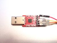
| + | To communicate to SJONE board over UART there is a need an USB to serial converter and a MAX232 circuit to convert the voltage levels to TTL, which the SJONE board understands. Instead it’s better to use a USB-to-UART converter to avoid the multiple conversions. This is done using CP2102 IC, which is similar to a FTDI chip.</p> | ||
| + | </td> | ||
| + | <td> | ||
| + | [[File:S15_244_Grp10_Ges_UART_to_USB.JPG|200px]]<br> | ||
| + | <center>Figure 5: USB-to-UART chip</center><br> | ||
| + | </td> | ||
| + | </tr> | ||
| + | </table> | ||
=== Hardware Interface === | === Hardware Interface === | ||
| − | + | <table> | |
| + | <tr> | ||
| + | <td valign="top" width=1150px> | ||
| + | <center><i>Pin connections for IR Sensor to Multiplexer:</i></center><br> | ||
| + | [[File:S15 244 Grp10 Ges sensor-to-mux.png|600px|center]]<br> | ||
| + | <center>Figure 6: Pin connections for IR Sensor to Multiplexer</center><br> | ||
| + | </td> | ||
| + | </tr> | ||
| + | </table> | ||
| + | <table> | ||
| + | <tr> | ||
| + | <td valign="top" align="center" width=600px> | ||
| + | <br> | ||
| + | <i>Pin connections on SJOne board:</i><br> | ||
| + | [[File:S15 244 Grp10 Ges sjone pinouts.png|400px]]<br><br> | ||
| + | Figure 7: Pin connections on SJOne board<br> | ||
| + | </td> | ||
| + | <td valign="top" align="center"> | ||
| + | <br> | ||
| + | <i>Connections between SJOne board and USB-to-UART Converter:</i><br> | ||
| + | [[File:S15 244 Grp10 Ges SJOne to UART.JPG|360px|x400px]]<br> | ||
| + | Figure 8: Connections between SJOne board and USB-to-UART Converter<br> | ||
| + | </td> | ||
| + | </tr> | ||
| + | </table> | ||
=== Software Design === | === Software Design === | ||
| − | + | <table> | |
| + | <tr> | ||
| + | <td valign="top" align="justify" width=850px> | ||
| + | <b><font size="2.5">Initialization</font></b><br> | ||
| + | <p style="text-indent: 1em; text-align: justify;"> | ||
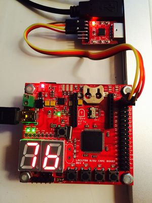
| + | SJOne board has 3 ADC pins exposed on Port 0 (0.26) and Port 1 (1.30 and 1.31). To use these pins as ADC, the function should be selected in PINSEL.</p> | ||
| + | <p style="text-indent: 1em; text-align: justify;"> | ||
| + | The GPIO pins on Port 2 are connected to the select pins on multiplexer. These pins should be initialized as output pins. | ||
| + | Once, initialization is completed, the function for normalizing the sensor values is called. | ||
| + | </p> | ||
| + | </td> | ||
| + | <td valign="top"> | ||
| + | <br> | ||
| + | [[File:S15 244 Grp10 Ges sensor init.png|center|160px|x400px]]<br> | ||
| + | <center>Figure 9: Flowchart for initialization of ADC and multiplexer </center><br> | ||
| + | </td> | ||
| + | </tr> | ||
| + | <tr> | ||
| + | <td valign="top" align="justify" width=850px> | ||
| + | <br><br> | ||
| + | <p style="text-indent: 1em; text-align: justify;"> | ||
| + | SJOne board uses UART 3 to communicate with the QT application. UART 3 is initialized to baud rate of 9600 with receiver buffer as 0 and transmission buffer as 32 bytes. Once initialization is completed, the function for processing sensor values is called.</p> | ||
| + | </td> | ||
| + | <td valign="top"> | ||
| + | <br><br> | ||
| + | [[File:S15 244 Grp10 Ges process init.png|center|160px|x300px]]<br> | ||
| + | <center>Figure 10: Flowchart for initialization of UART and process </center><br> | ||
| + | </td> | ||
| + | </tr> | ||
| + | </table> | ||
| + | |||
| + | <table> | ||
| + | <tr> | ||
| + | <td valign="top" align="justify" width=850px> | ||
| + | <b><font size="2.5">Filter Algorithm</font></b><br> | ||
| + | <p style="text-indent: 1em; text-align: justify;"> | ||
| + | The current value of sensor is fetched by setting the corresponding values on the multiplexer select pins and reading the output of the ADC. A queue of size 5 is maintained and the fetched value is inserted at the tail of the queue. This queue is sorted using bubble sort. The median value of the queue is checked to be greater than 2000 (sensor returns a voltage corresponding to a value greater than 2000 when the hand is near enough to it) and gesture array for that sensor is set accordingly.</p> | ||
| + | </td> | ||
| + | <td valign="top"> | ||
| + | <br> | ||
| + | [[File:S15 244 Grp10 Ges filter task.png|center|320px]]<br> | ||
| + | <center>Figure 11: Flowchart for filter algorithm</center><br> | ||
| + | </td> | ||
| + | </tr> | ||
| + | </table> | ||
| + | |||
| + | <table> | ||
| + | <tr> | ||
| + | <td valign="top" align="justify" width=900px> | ||
| + | <b><font size="2.5">Gesture Recognition Algorithm</font></b><br> | ||
| + | <p style="text-indent: 1em; text-align: justify;"> | ||
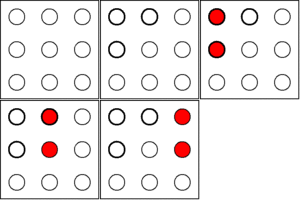
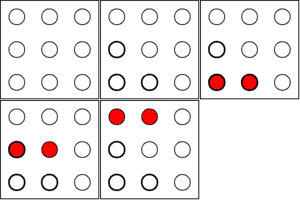
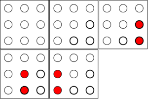
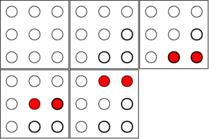
| + | Different sets of sensors are monitored in order to recognize a valid pattern in the sensor output and thereby recognize the gesture pattern.<br> | ||
| + | (We have assumed that the sensors are numbered 0 through 8 and the corresponding value for the sensor is set by the filter algorithm in gesture[] array). <br></p> | ||
| + | </td> | ||
| + | </tr> | ||
| + | </table> | ||
| + | |||
| + | <table> | ||
| + | <tr> | ||
| + | <td rowspan="2" valign="top"> | ||
| + | <i>Pattern 1:</i><br> | ||
| + | [[File:S15 244 Grp10 Ges process1.png|left|400px]]<br> | ||
| + | <center>Figure 12: Flowchart for selection of pattern 1 </center><br> | ||
| + | </td> | ||
| + | <td valign="top" align="justify"><br> | ||
| + | <p style="text-indent: 1em; text-align: justify;"> | ||
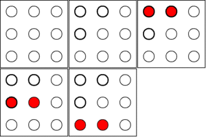
| + | Here the three sensors present at the top left corner are monitored. | ||
| + | * If sensor1 value is zero | ||
| + | ** Check the values of sensors in the second column. If the combination of first two or last two sensors is 1, go to next step. Else, update the gesture array for these sensors and check. | ||
| + | *** Check the values of sensors in the third column. If the combination of first two or last two sensors is 1, go to next step. Else, update the gesture array for these sensors and check. | ||
| + | *** Send “Right” to UART 3. | ||
| + | </p> | ||
| + | </td> | ||
| + | <td valign="top"> | ||
| + | <br><br> | ||
| + | [[File:S15 244 Grp10 Ges tlright.gif|center|100px]]<br> | ||
| + | </td> | ||
| + | </tr> | ||
| + | <tr> | ||
| + | <td valign="top" align="justify"><br> | ||
| + | * If sensor3 value is zero | ||
| + | ** Check the values of sensors in the second row. If the combination of first two or last two sensors is 1, go to next step. Else, update the gesture array for these sensors and check. | ||
| + | *** Check the values of sensors in the third row. If the combination of first two or last two sensors is 1, go to next step. Else, update the gesture array for these sensors and check. | ||
| + | *** Send “Down ” to UART 3. | ||
| + | </td> | ||
| + | <td valign="top"> | ||
| + | <br><br> | ||
| + | [[File:S15 244 Grp10 Ges tldown.gif|center|100px]]<br> | ||
| + | </td> | ||
| + | </tr> | ||
| + | </table> | ||
| + | |||
| + | <table> | ||
| + | <tr> | ||
| + | <td rowspan="2" valign="top"> | ||
| + | <i>Pattern 2:</i><br> | ||
| + | [[File:S15 244 Grp10 Ges process2.png|left|400px]]<br> | ||
| + | <center>Figure 13: Flowchart for selection of pattern 2 </center><br> | ||
| + | </td> | ||
| + | <td valign="top" align="justify"><br> | ||
| + | <p style="text-indent: 1em; text-align: justify;"> | ||
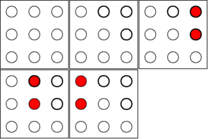
| + | Here the three sensors present at the top right corner are monitored. | ||
| + | * If sensor1 value is zero | ||
| + | ** Check the values of sensors in the second column. If the combination of first two or last two sensors is 1, go to next step. Else, update the gesture array for these sensors and check. | ||
| + | *** Check the values of sensors in the first column. If the combination of first two or last two sensors is 1, go to next step. Else, update the gesture array for these sensors and check. | ||
| + | *** Send “Left ” to UART 3. | ||
| + | </p> | ||
| + | </td> | ||
| + | <td valign="top"> | ||
| + | <br><br> | ||
| + | [[File:S15 244 Grp10 Ges trleft.gif|center|100px]]<br> | ||
| + | </td> | ||
| + | </tr> | ||
| + | <tr> | ||
| + | <td valign="top" align="justify"><br> | ||
| + | * If sensor5 value is zero | ||
| + | ** Check the values of sensors in the second row. If the combination of first two or last two sensors is 1, go to next step. Else, update the gesture array for these sensors and check. | ||
| + | *** Check the values of sensors in the third row. If the combination of first two or last two sensors is 1, go to next step. Else, update the gesture array for these sensors and check. | ||
| + | *** Send “Down ” to UART 3. | ||
| + | </td> | ||
| + | <td valign="top"> | ||
| + | <br><br> | ||
| + | [[File:S15 244 Grp10 Ges trdown.gif|center|100px]]<br> | ||
| + | </td> | ||
| + | </tr> | ||
| + | </table> | ||
| + | |||
| + | <table> | ||
| + | <tr> | ||
| + | <td rowspan="2" valign="top"> | ||
| + | <i>Pattern 3:</i><br> | ||
| + | [[File:S15 244 Grp10 Ges process3.png|left|400px]]<br> | ||
| + | <center>Figure 14: Flowchart for selection of pattern 3 </center><br> | ||
| + | </td> | ||
| + | <td valign="top" align="justify"><br> | ||
| + | <p style="text-indent: 1em; text-align: justify;"> | ||
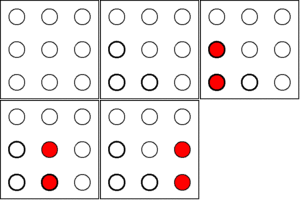
| + | Here the three sensors present at the bottom left corner are monitored. | ||
| + | * If sensor7 value is zero | ||
| + | ** Check the values of sensors in the second column. If the combination of first two or last two sensors is 1, go to next step. Else, update the gesture array for these sensors and check. | ||
| + | *** Check the values of sensors in the third column. If the combination of first two or last two sensors is 1, go to next step. Else, update the gesture array for these sensors and check. | ||
| + | *** Send “Right ” to UART 3. | ||
| + | </p> | ||
| + | </td> | ||
| + | <td valign="top"> | ||
| + | <br><br> | ||
| + | [[File:S15 244 Grp10 Ges blright.gif|center|100px]]<br> | ||
| + | </td> | ||
| + | </tr> | ||
| + | <tr> | ||
| + | <td valign="top" align="justify"><br> | ||
| + | * If sensor3 value is zero | ||
| + | ** Check the values of sensors in the second row. If the combination of first two or last two sensors is 1, go to next step. Else, update the gesture array for these sensors and check. | ||
| + | *** Check the values of sensors in the first row. If the combination of first two or last two sensors is 1, go to next step. Else, update the gesture array for these sensors and check. | ||
| + | *** Send “Up ” to UART 3. | ||
| + | </td> | ||
| + | <td valign="top"> | ||
| + | <br><br> | ||
| + | [[File:S15 244 Grp10 Ges blup.gif|center|100px]]<br> | ||
| + | </td> | ||
| + | </tr> | ||
| + | </table> | ||
| + | |||
| + | <table> | ||
| + | <tr> | ||
| + | <td rowspan="2" valign="top"> | ||
| + | <i>Pattern 4:</i><br> | ||
| + | [[File:S15 244 Grp10 Ges process4.png|left|400px]]<br> | ||
| + | <center>Figure 15: Flowchart for selection of pattern 4 </center><br> | ||
| + | </td> | ||
| + | <td valign="top" align="justify"><br> | ||
| + | <p style="text-indent: 1em; text-align: justify;"> | ||
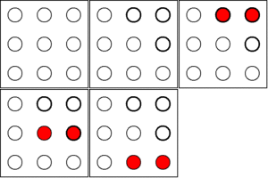
| + | Here the three sensors present at the bottom right corner are monitored. | ||
| + | * If sensor7 value is zero | ||
| + | ** Check the values of sensors in the second column. If the combination of first two or last two sensors is 1, go to next step. Else, update the gesture array for these sensors and check. | ||
| + | *** Check the values of sensors in the first column. If the combination of first two or last two sensors is 1, go to next step. Else, update the gesture array for these sensors and check. | ||
| + | *** Send “Left ” to UART 3. | ||
| + | </p> | ||
| + | </td> | ||
| + | <td valign="top"> | ||
| + | <br><br> | ||
| + | [[File:S15 244 Grp10 Ges brleft.gif|center|100px]]<br> | ||
| + | </td> | ||
| + | </tr> | ||
| + | <tr> | ||
| + | <td valign="top" align="justify"><br> | ||
| + | * If sensor5 value is zero | ||
| + | ** Check the values of sensors in the second row. If the combination of first two or last two sensors is 1, go to next step. Else, update the gesture array for these sensors and check. | ||
| + | *** Check the values of sensors in the first row. If the combination of first two or last two sensors is 1, go to next step. Else, update the gesture array for these sensors and check. | ||
| + | *** Send “Up ” to UART 3. | ||
| + | </td> | ||
| + | <td valign="top"> | ||
| + | <br><br> | ||
| + | [[File:S15 244 Grp10 Ges brup.gif|center|100px]]<br> | ||
| + | </td> | ||
| + | </tr> | ||
| + | </table> | ||
| + | |||
| + | <table> | ||
| + | <tr> | ||
| + | <td valign="top" align="justify" width=850px> | ||
| + | <b><font size="2.5">Application Development</font></b><br> | ||
| + | <i><font size="2">Qt Software</font></i><br> | ||
| + | <p style="text-indent: 1em; text-align: justify;"> | ||
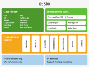
| + | Qt is a cross-platform application framework that is widely used in developing application software that can be run on various software and hardware platforms with little or no change in the underlying codebase while having the speed and the power of native application.</p> | ||
| + | <p style="text-indent: 1em; text-align: justify;"> | ||
| + | It is mainly used to make GUI based applications but there can be applications such as consoles or command-line applications developed in Qt. Qt is preferred by many application programmers as it helps in developing GUI applications in C++ as it uses the standard C++ libraries for backend.</p> | ||
| + | <p style="text-indent: 1em; text-align: justify;"> | ||
| + | Platforms supported by Qt are: | ||
| + | * Android | ||
| + | * Embedded Linux | ||
| + | * Integrity | ||
| + | * iOS | ||
| + | * OSX | ||
| + | * QNX | ||
| + | * VxWorks | ||
| + | * Waylands | ||
| + | * Windows | ||
| + | * Windows CE | ||
| + | * Windows RT | ||
| + | * X11 | ||
| + | </p> | ||
| + | <p style="text-indent: 1em; text-align: justify;"> | ||
| + | Qt applications are highly portable from one platform to other as Qt first runs a Qmake function before compiling the source code. It is very similar to ‘cmake’ which is used for cross platform compilation of any source code. The qmake auto generates a makefile depending on the operating system and the compiler used for the project. So if a project is to be ported from windows to linux based system then the qmake auto generated a new makefile with arguments and parameters that the g++ compiler expects.</p> | ||
| + | </td> | ||
| + | <td width=300px align="center"> | ||
| + | [[File:S15 244 Grp10 Ges qtdevices.png|300px]]<br> | ||
| + | <center>Figure 16: Devices supporting Qt</center><br> | ||
| + | [[File:S15 244 Grp10 Ges qt-sdk.png|300px]]<br> | ||
| + | <center>Figure 17: Qt-SDK</center><br> | ||
| + | </td> | ||
| + | </tr> | ||
| + | </table> | ||
| + | |||
| + | <table> | ||
| + | <tr> | ||
| + | <td valign="top" align="justify" width=1150px> | ||
| + | <i><font size="2">Gesture Recognition application on Qt</font></i><br> | ||
| + | <p style="text-indent: 1em; text-align: justify;"> | ||
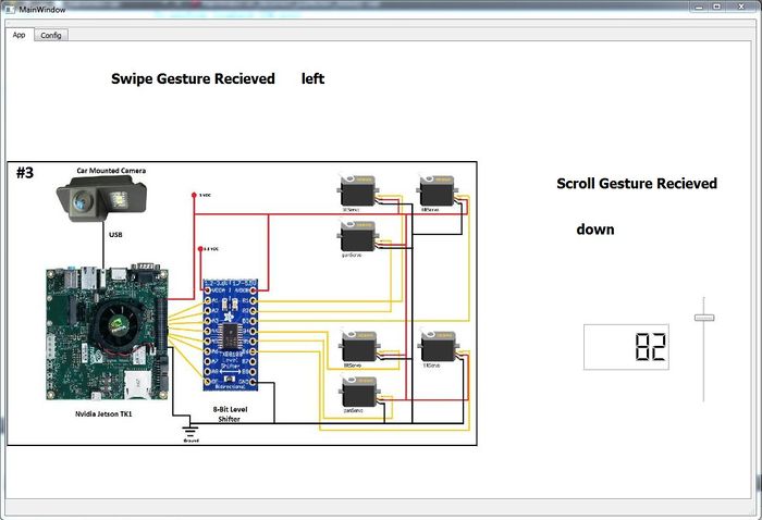
| + | Once the gesture is recognized on the SJONE board, a message is sent over UART3 stating which gesture was sensed. The Qt application gets this message from the COM port and scrolls the images left and right based on the left/right gesture and it moves a vertical slider up and down which in turn changes the value on a LCD screen display.</p> | ||
| + | <p style="text-indent: 1em; text-align: justify;"> | ||
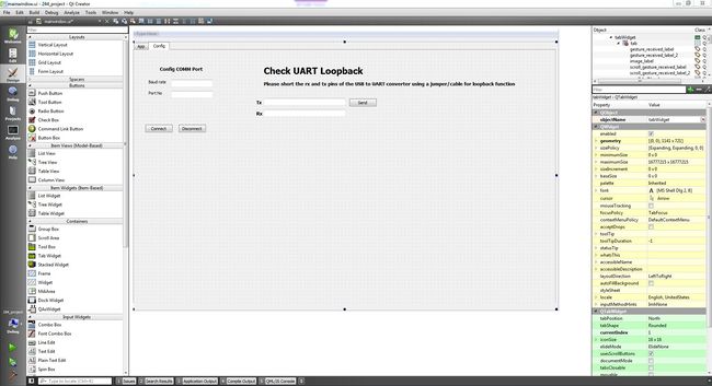
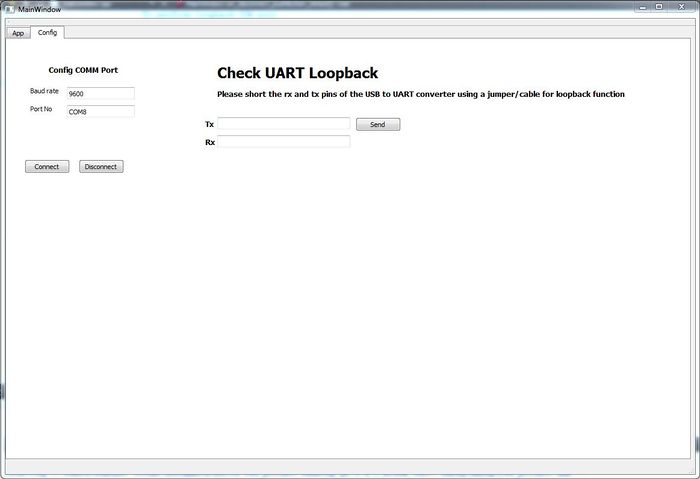
| + | The application opens up in a window that has 2 tabs, config and App. The config tab includes the fields required to open the COMM port and test the COMM port using a loopback connection.</p> | ||
| + | [[File:S15 244 Grp10 Ges qt tab1.JPG|center|650px|x434px]]<br> | ||
| + | <center>Figure 18: Configuration Tab</center><br> | ||
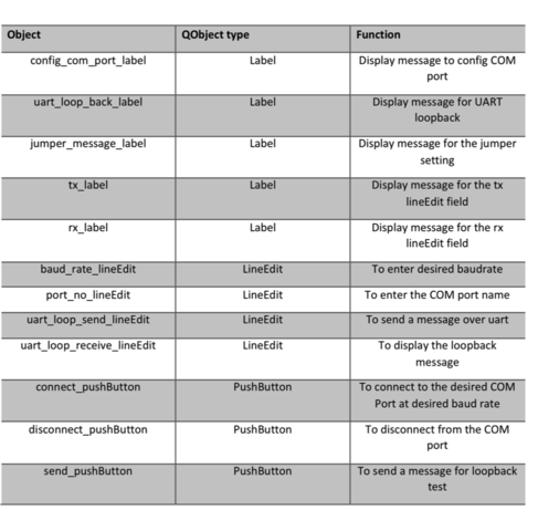
| + | <p style="text-indent: 1em; text-align: justify;">This tab has the following QObjects.</p><br> | ||
| + | [[File:S15 244 Grp10 Ges table1.png|center|650px|x480px]]<br> | ||
| + | <center>Table 1: QObjects used for Configuration Tab</center><br> | ||
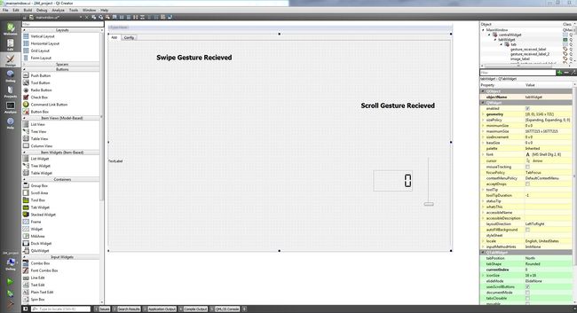
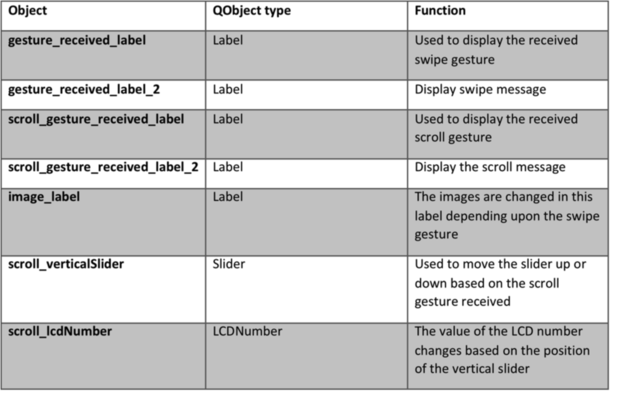
| + | <p style="text-indent: 1em; text-align: justify;">The App tab includes the objects required to change images and change the value in the vertical slider and lcd number display.</p><br> | ||
| + | [[File:S15 244 Grp10 Ges qt tab2.JPG|center|650px|x434px|]]<br> | ||
| + | <center>Figure 19: Application Tab</center><br> | ||
| + | <p style="text-indent: 1em; text-align: justify;">This tab has the following Qobjects.</p><br> | ||
| + | [[File:S15 244 Grp10 Ges table2.png|center|650px|x420px]]<br> | ||
| + | <center>Table 2: QObjects used for Application Tab</center><br> | ||
| + | |||
| + | |||
| + | </td> | ||
| + | </tr> | ||
| + | </table> | ||
=== Implementation === | === Implementation === | ||
| − | This | + | ==== Application Logic ==== |
| + | <table> | ||
| + | <tr> | ||
| + | <td valign="top" align="justify" width=1150px> | ||
| + | <p style="text-indent: 1em; text-align: justify;"> | ||
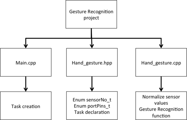
| + | The below diagram shows the setup of the files used in the project.</p><br> | ||
| + | [[File:S15 244 Grp10 Ges code structure.png|center|600px|x400px]]<br> | ||
| + | <center>Figure 20: Code Structure tree diagram</center><br><br> | ||
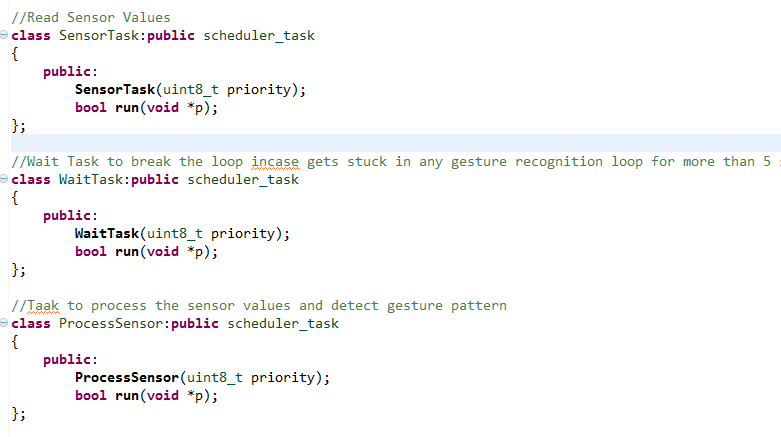
| + | <p style="text-indent: 1em; text-align: justify;">The main function creates the tasks required for the application namely, SensorTask, WaitTask and ProcessSensor.</p><br> | ||
| + | [[File:S15 244 Grp10 Ges main.PNG|center]]<br> | ||
| + | <center>Figure 21: Main file snippet</center><br><br> | ||
| + | The tasks are declared in Hand_Gesture.hpp file.<br> | ||
| + | [[File:S15 244 Grp10 Ges gesturehpp.PNG|center]]<br> | ||
| + | <center>Figure 22: Header file snippet</center><br> | ||
| + | <p style="text-indent: 1em; text-align: justify;"> | ||
| + | This file also includes the enumerations required in the program logic. | ||
| + | * sensorNo_t: This enumeration assigns numbers to the sensor from 0 through 8. | ||
| + | * portPins_t: This enumeration assigns the shifting logic to P2_0 through P2_5 for better readability.</p> | ||
| + | <p style="text-indent: 1em; text-align: justify;"> | ||
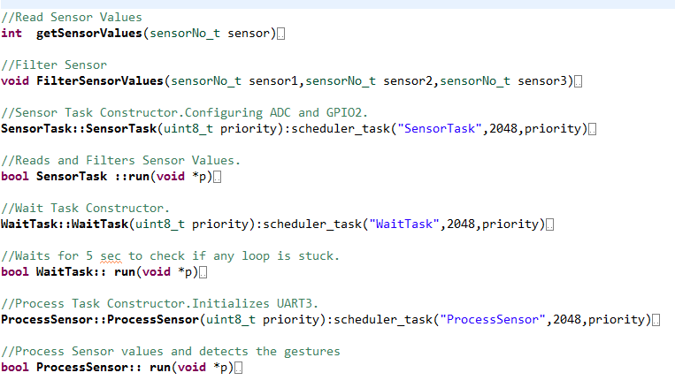
| + | Hand_Gesture.cpp file contains the definitions of all the functions as listed below.</p><br> | ||
| + | [[File:S15 244 Grp10 Ges gesturecpp.PNG|center]]<br> | ||
| + | <center>Figure 23: Source File snippet showing the function defined</center><br> | ||
| + | <p style="text-indent: 1em; text-align: justify;"> | ||
| + | The WaitTask is used internally in ProcessSensor to wait for values of sensor to change while navigating through the above described algorithm. This task enables the system to wait for maximum of 5 seconds to receive any change of values in the sensor. If after 5 seconds, the sensor values are not as desired by the algorithm (to proceed to next stage), the sensor values are concluded to be false positives and further execution is skipped.</p> | ||
| + | |||
| + | <p style="text-indent: 1em; text-align: justify;">The constructor of SensorTask includes the initialization of pins for ADC and Port 2 pins used as select lines for the multiplexer.</p><br> | ||
| + | [[File:S15 244 Grp10 Ges pins init.png|center]]<br> | ||
| + | <center>Figure 24: Pin initialization</center><br> | ||
| + | <p style="text-indent: 1em; text-align: justify;">UART 3 is initialized using the Singleton pattern.</p><br> | ||
| + | [[File:S15 244 Grp10 Ges Singleton.png|center]]<br> | ||
| + | <center>Figure 25: UART initialization using Singleton Pattern</center><br> | ||
| + | <p style="text-indent: 1em; text-align: justify;">The init function of UART is used to initialize UART 3 to communicate at the baud rate of 9600. Since the application will only be sending values to the Qt application and not expecting any replies, the receive buffer is set to zero and the transmission buffer is set to 32 bytes.</p><br> | ||
| + | [[File:S15 244 Grp10 Ges UART init.png|center]]<br> | ||
| + | <center>Figure 26: UART driver initialization</center><br><br> | ||
| + | </td> | ||
| + | </tr> | ||
| + | </table> | ||
| + | |||
| + | ==== Qt Application Implementation ==== | ||
| + | |||
| + | <table> | ||
| + | <tr> | ||
| + | <td valign="top" align="justify" width=1150px> | ||
| + | <i>Includes and app initialization</i><br> | ||
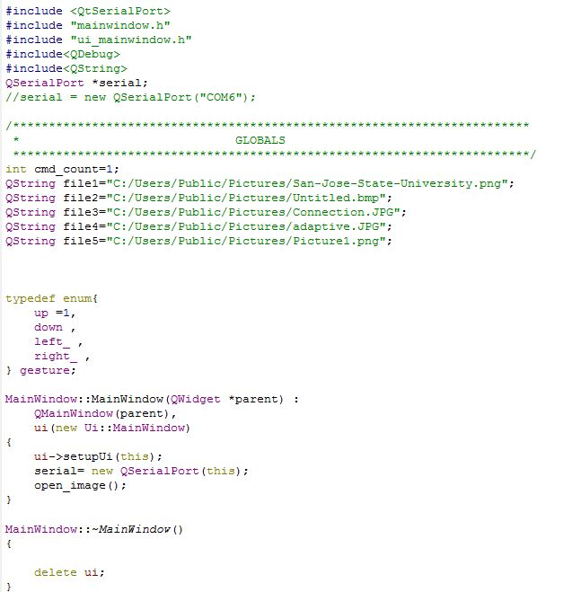
| + | This sections includes all header files required for the app and the constructor and destructor for the app. | ||
| + | As we are displaying multiple images in the app the path of these images have to be hardcoded. We also define an enum to capture the received gesture. An instance of the serial port is also created in the constructor, and an initial welcome image (SJSU logo) is displayed on the app.<br> | ||
| + | [[File:S15 244 Grp10 Ges qt includes.JPG|center]]<br> | ||
| + | <center>Figure 27: Snippet of initialization</center><br> | ||
| + | <i>Configuration COM port</i><br> | ||
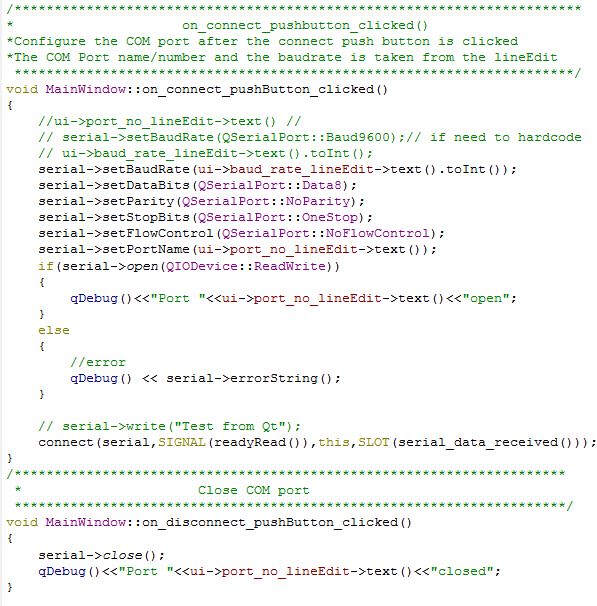
| + | The COM port is configured in this section of the code, the name of the COM port and the baud rate is picked up from the lineEdits present on the config tab and passed to populate the structure of the serial port. If there is an error opening the COM port then an error message is displayed. The COM port is closed once the disconnect button is pressed.<br> | ||
| + | [[File:S15 244 Grp10 Ges qt comport.JPG|center]]<br> | ||
| + | <center>Figure 28: Configuration of COM port</center><br> | ||
| + | <i>Serial receive and loopback test</i><br> | ||
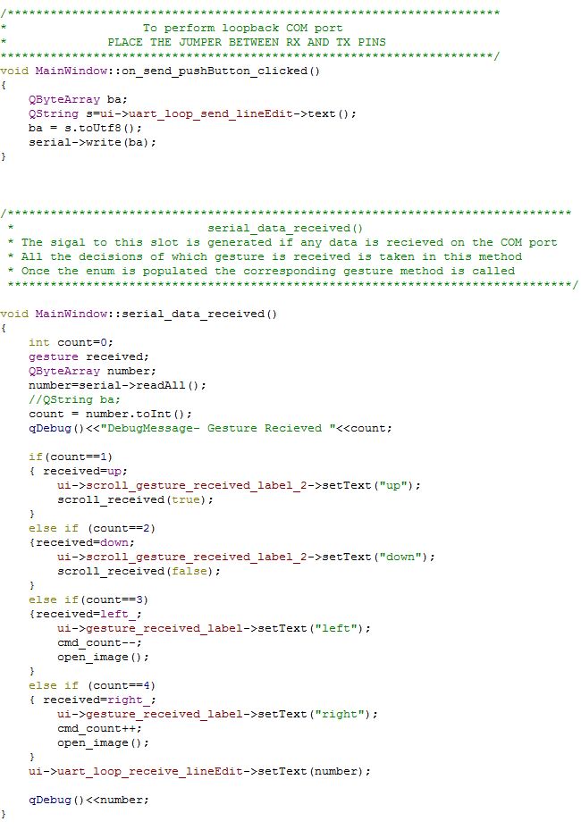
| + | This section includes the code to copy all the data received in the receive buffer parse it and take the decision on which kind of gesture was received and take the appropriate decision. The loop back section picks up anything written on the Tx lineEdit and displays the received buffer on the rx lineEdit.<br> | ||
| + | [[File:S15 244 Grp10 Ges qt recv loopback.JPG|center]]<br> | ||
| + | <center>Figure 29: Code to test serial receive using loopback</center><br> | ||
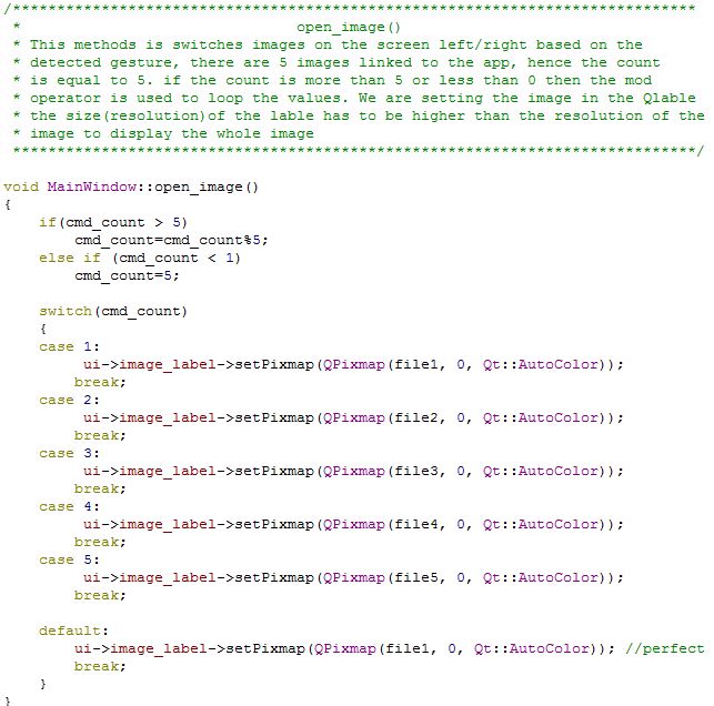
| + | <i>Open Image</i><br> | ||
| + | The logic to switch between images and to loop through the images is implemented here.<br> | ||
| + | [[File:S15 244 Grp10 Ges qt image.JPG|center]]<br> | ||
| + | <center>Figure 30: Code to switch between images</center><br> | ||
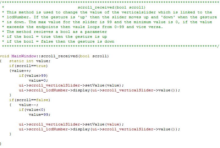
| + | <i>Scroll</i><br> | ||
| + | The position of the vertical slider is changed depending on the up/down gesture, the LCDnumber display is used to display the position (value) of the vertical slider. The value ranges from 0-99 and loops through if the value is greater 99 or smaller than 0.<br> | ||
| + | [[File:S15 244 Grp10 Ges qt scroll.JPG|center]]<br> | ||
| + | <center>Figure 31: Code to scroll the vertical slider</center><br> | ||
| + | </td> | ||
| + | </tr> | ||
| + | </table> | ||
| + | |||
| + | ==== Setup and Working ==== | ||
| + | <table> | ||
| + | <tr> | ||
| + | <td valign="top" align="justify" width=1150px> | ||
| + | <b>Sensor setup</b><br> | ||
| + | [[File:S15 244 Grp10 Ges sensor setup.jpg|center|450px|x600px]]<br> | ||
| + | <center>Figure 32: Sensor setup</center><br> | ||
| + | <br> | ||
| + | <b>Screenshots of Qt application</b><br> | ||
| + | [[File:S15 244 Grp10 Ges Qt config working.JPG|center|700px|x540px]]<br> | ||
| + | <center>Figure 33: Configuration screen</center><br> | ||
| + | [[File:S15 244 Grp10 Ges qt working demo.JPG|center|700px|x540px]]<br> | ||
| + | <center>Figure 34: Application screen</center><br> | ||
| + | </td> | ||
| + | </tr> | ||
| + | </table> | ||
== Testing & Technical Challenges == | == Testing & Technical Challenges == | ||
| − | + | <b>Challenge #1:</b><br> | |
| − | + | <p style="text-indent: 1em; text-align: justify;"> | |
| + | The sensor produces many spikes giving false positive outputs.</p> | ||
| − | + | <i>Resolution:</i><br> | |
| + | <p style="text-indent: 1em; text-align: justify;"> | ||
| + | In order to overcome spikes received and deal with false positive, normalization of the sensor output is done. A circular queue of size 5 is maintained for each sensor and each value received from the ADC is stored at the end on the queue. This queue is then sorted and only the median value is considered for computation. This reduces the false positives to a great extent.<br> | ||
| + | </p><br> | ||
| + | <b>Challenge #2:</b><br> | ||
| + | <p style="text-indent: 1em; text-align: justify;"> | ||
| + | Number of sensors used was far greater than the available ADC pins.</p> | ||
| − | == | + | <i>Resolution:</i><br> |
| − | + | <p style="text-indent: 1em; text-align: justify;"> | |
| + | Even if we had 9 ADC pins converting values of 9 sensors, we would still be reading the each sensor one by one. Keeping this in mind, in order to overcome the deficit of ADC pins, we have used multiplexer which takes the input from 3 sensors at a time and gives the output of only the selected sensor. In this way, we could read the output of any sensor at any given point of time. The introduction of multiplexer introduces a lag but this lag is not long enough to hinder the operation of the application.<br> | ||
| + | </p><br> | ||
| + | <b>Challenge #3:</b><br> | ||
| + | <p style="text-indent: 1em; text-align: justify;"> | ||
| + | Qt being a new application for all the team members, it was a challenge to learn its programming style and use the objects.<br> | ||
| + | </p><br> | ||
| + | <b>Challenge #4:</b><br> | ||
| + | <p style="text-indent: 1em; text-align: justify;"> | ||
| + | Setting up the serial port communication in Qt. | ||
| + | </p> | ||
== Conclusion == | == Conclusion == | ||
| − | + | <p style="text-indent: 1em; text-align: justify;"> | |
| + | Gesture recognition using IR sensors was a very interesting and challenging project. The main areas where we enjoyed working were the development of the gesture recognition algorithm and sensor filter algorithm. | ||
| + | This project increased our knowledge in: | ||
| + | * Developing filters for analog sensors | ||
| + | * Working with the sensor itself | ||
| + | * Reading datasheets for the multiplexer and sensor | ||
| + | * Hands-on experience in Qt application | ||
| + | * Using Singleton pattern for UART | ||
| + | </p> | ||
| + | |||
| + | <p style="text-indent: 1em; text-align: justify;"> | ||
| + | This project was developed in a small scale. Further work can be done to integrate this project in devices, which would help blind people to use software, which require manual intervention, seamlessly. | ||
| + | </p> | ||
=== Project Video === | === Project Video === | ||
| − | + | [https://youtu.be/Dev3LnjyL3Y Gesture Recognition using IP Proximity Sensors] | |
=== Project Source Code === | === Project Source Code === | ||
| Line 195: | Line 648: | ||
== References == | == References == | ||
=== Acknowledgement === | === Acknowledgement === | ||
| − | + | <p style="text-indent: 1em; text-align: justify;"> | |
| + | All the components where procurred from Amazon, Adafruit and digikey. We are thankful to Preet for his continuous guidance during the project. | ||
| + | </p> | ||
=== References Used === | === References Used === | ||
| − | + | <p style="width: 700px; text-align: justify;"> | |
| − | + | [http://www.sharpsma.com/webfm_send/1208 IR Sensor Data Sheet]<br> | |
| − | = | + | [http://www.nxp.com/documents/data_sheet/LPC1769_68_67_66_65_64_63.pdf LPC_USER_MANUAL]<br> |
| − | + | [http://www.st.com/web/en/resource/technical/document/datasheet/CD00002398.pdf Multiplexer Data Sheet]<br> | |
| + | [http://en.wikipedia.org/wiki/Qt_%28software%29 QT Software]<br> | ||
| + | [http://www.socialledge.com/sjsu/index.php?title=S14:_Virtual_Dog Filter code refered from Spring'14 project Virtual Dog] | ||
| + | </p> | ||
Latest revision as of 03:43, 25 May 2015
Contents
Abstract
The aim of the project is to develop hand gesture recognition system using grid of IR proximity sensors. Various hand gestures like swipe, pan etc. can be recognized. These gestures can be used to control different devices or can be used in various applications. The system will recognize different hand gestures based on the values received from IR proximity sensors. We have used Qt to develop the application to demonstrate the working of the project.
Objectives & Introduction
We use various hand gestures in our day-to-day life to communicate while trying to explain someone something, direct them somewhere etc. It would be so cool if we could communicate with various applications running on the computers or different devices around us understand the hand gestures and give the expected output. In order to achieve this, we are using a 3-by-3 grid of analog IR proximity sensors and connecting these sensors via multiplexers to the ADC pins on SJOne Board. As a hand is moved in front of the sensors, the sensor values would in a particular pattern enabling us to detect the gesture and instruct the application to perform the corresponding action.
Team Members & Responsibilities
- Harita Parekh
- Implementing algorithm for gesture recognition
- Implementation of sensor data filters
- Shruti Rao
- Implementing algorithm for gesture recognition
- Interfacing of sensors, multiplexers and controller
- Sushant Potdar
- Implementation of final sensor grid
- Development of the application module
Schedule
| Week# | Start Date | End Date | Task | Status | Actual Completion Date |
|---|---|---|---|---|---|
| 1 | 3/22/2015 | 3/28/2015 | Research on the sensors, order sensors and multiplexers | Completed | 3/28/2015 |
| 2 | 3/29/2015 | 4/4/2015 | Read the data sheet for sensors and understand its working. Test multiplexers | Completed | 4/04/2015 |
| 3 | 4/05/2015 | 4/11/2015 | Interfacing of sensors, multiplexers and controller | Completed | 4/15/2015 |
| 4 | 4/12/2015 | 4/18/2015 |
|
Completed | 4/25/2015 |
| 5 | 4/19/2015 | 4/25/2015 |
|
Completed | 5/02/2015 |
| 6 | 4/26/2015 | 5/02/2015 |
|
Completed | 5/09/2015 |
| 7 | 5/03/2015 | 5/09/2015 | Testing and bug fixes | Completed | 5/15/2015 |
| 8 | 5/10/2015 | 5/16/2015 | Testing and final touches | Completed | 5/22/2015 |
| 9 | 5/21/2015 | 5/24/2015 | Report Completion | Completed | 5/24/2015 |
| 10 | 5/25/2015 | 5/25/2015 | Final demo | Scheduled | 5/25/2015 |
Parts List & Cost
| SR# | Component Name | Quantity | Price per component | Total Price |
|---|---|---|---|---|
| 1 | Sharp Distance Measuring Sensor Unit (GP2Y0A21YK0F) | 9 | $14.95 | $134.55 |
| 2 | STMicroelectronics Dual 4-Channel Analog Multiplexer/Demultiplexer (M74HC4052) | 3 | $0.56 | $1.68 |
| 3 | SJ-One Board | 1 | $80 | $80 |
| 4 | USB-to-UART converter | 1 | $7 | $7 |
| Total (excluding shipping and taxes) | $223.23 | |||
Design & Implementation
Hardware Design
The image shows the setup of the project.
|
|
|
|
Proximity Sensor:
This sensor by Sharp measures the distance from an obstacle by bouncing IR rays off the obstacle. This sensor can measure distances from 10 to 80 cms. The sensor returns an analog voltage corresponding to the distance from the obstacle. Depending on which sensor returns valid values, validations could be made and hand movement can be determined. The voltage returned by the sensor increases as the obstacle approaches the sensor. There is no external circuitry required for this sensor. The operating voltage recommended for this sensor is 4.5V to 5.5V. |
|
|
Multiplexer:
The chip used in the project is M74HC4052 from STMicroelectronics. This is a dual 4-channel multiplexer/demultiplexer. Due to shortage of ADC pins to interface with the sensors, use of multiplexer is required. The multiplexer takes input from three sensors and enables only one of them at the output. The program logic decides which sensor’s output should be enabled at the multiplexer’s output. A and B control signals select one of the channel out of the four. The operating voltage for the multiplexer is 2 to 6V. |
|
|
USB-to-UART converter:
To communicate to SJONE board over UART there is a need an USB to serial converter and a MAX232 circuit to convert the voltage levels to TTL, which the SJONE board understands. Instead it’s better to use a USB-to-UART converter to avoid the multiple conversions. This is done using CP2102 IC, which is similar to a FTDI chip. |
|
Hardware Interface
|
|
|
|
|
Software Design
|
Initialization SJOne board has 3 ADC pins exposed on Port 0 (0.26) and Port 1 (1.30 and 1.31). To use these pins as ADC, the function should be selected in PINSEL. The GPIO pins on Port 2 are connected to the select pins on multiplexer. These pins should be initialized as output pins. Once, initialization is completed, the function for normalizing the sensor values is called. |
|
|
SJOne board uses UART 3 to communicate with the QT application. UART 3 is initialized to baud rate of 9600 with receiver buffer as 0 and transmission buffer as 32 bytes. Once initialization is completed, the function for processing sensor values is called. |
|
|
Filter Algorithm The current value of sensor is fetched by setting the corresponding values on the multiplexer select pins and reading the output of the ADC. A queue of size 5 is maintained and the fetched value is inserted at the tail of the queue. This queue is sorted using bubble sort. The median value of the queue is checked to be greater than 2000 (sensor returns a voltage corresponding to a value greater than 2000 when the hand is near enough to it) and gesture array for that sensor is set accordingly. |
|
|
Gesture Recognition Algorithm
Different sets of sensors are monitored in order to recognize a valid pattern in the sensor output and thereby recognize the gesture pattern. |
|
Pattern 1: |
Here the three sensors present at the top left corner are monitored.
|
|
|
|
|
Pattern 2: |
Here the three sensors present at the top right corner are monitored.
|
|
|
|
|
Pattern 3: |
Here the three sensors present at the bottom left corner are monitored.
|
|
|
|
|
Pattern 4: |
Here the three sensors present at the bottom right corner are monitored.
|
|
|
|
|
Application Development Qt is a cross-platform application framework that is widely used in developing application software that can be run on various software and hardware platforms with little or no change in the underlying codebase while having the speed and the power of native application. It is mainly used to make GUI based applications but there can be applications such as consoles or command-line applications developed in Qt. Qt is preferred by many application programmers as it helps in developing GUI applications in C++ as it uses the standard C++ libraries for backend. Platforms supported by Qt are:
Qt applications are highly portable from one platform to other as Qt first runs a Qmake function before compiling the source code. It is very similar to ‘cmake’ which is used for cross platform compilation of any source code. The qmake auto generates a makefile depending on the operating system and the compiler used for the project. So if a project is to be ported from windows to linux based system then the qmake auto generated a new makefile with arguments and parameters that the g++ compiler expects. |
|
|
Gesture Recognition application on Qt Once the gesture is recognized on the SJONE board, a message is sent over UART3 stating which gesture was sensed. The Qt application gets this message from the COM port and scrolls the images left and right based on the left/right gesture and it moves a vertical slider up and down which in turn changes the value on a LCD screen display. The application opens up in a window that has 2 tabs, config and App. The config tab includes the fields required to open the COMM port and test the COMM port using a loopback connection. This tab has the following QObjects. The App tab includes the objects required to change images and change the value in the vertical slider and lcd number display. This tab has the following Qobjects.
|
Implementation
Application Logic
|
The below diagram shows the setup of the files used in the project. The main function creates the tasks required for the application namely, SensorTask, WaitTask and ProcessSensor. The tasks are declared in Hand_Gesture.hpp file. This file also includes the enumerations required in the program logic.
Hand_Gesture.cpp file contains the definitions of all the functions as listed below. The WaitTask is used internally in ProcessSensor to wait for values of sensor to change while navigating through the above described algorithm. This task enables the system to wait for maximum of 5 seconds to receive any change of values in the sensor. If after 5 seconds, the sensor values are not as desired by the algorithm (to proceed to next stage), the sensor values are concluded to be false positives and further execution is skipped. The constructor of SensorTask includes the initialization of pins for ADC and Port 2 pins used as select lines for the multiplexer. UART 3 is initialized using the Singleton pattern. The init function of UART is used to initialize UART 3 to communicate at the baud rate of 9600. Since the application will only be sending values to the Qt application and not expecting any replies, the receive buffer is set to zero and the transmission buffer is set to 32 bytes. |
Qt Application Implementation
|
Includes and app initialization Configuration COM port Serial receive and loopback test Open Image Scroll |
Setup and Working
|
Sensor setup
|
Testing & Technical Challenges
Challenge #1:
The sensor produces many spikes giving false positive outputs.
Resolution:
In order to overcome spikes received and deal with false positive, normalization of the sensor output is done. A circular queue of size 5 is maintained for each sensor and each value received from the ADC is stored at the end on the queue. This queue is then sorted and only the median value is considered for computation. This reduces the false positives to a great extent.
Challenge #2:
Number of sensors used was far greater than the available ADC pins.
Resolution:
Even if we had 9 ADC pins converting values of 9 sensors, we would still be reading the each sensor one by one. Keeping this in mind, in order to overcome the deficit of ADC pins, we have used multiplexer which takes the input from 3 sensors at a time and gives the output of only the selected sensor. In this way, we could read the output of any sensor at any given point of time. The introduction of multiplexer introduces a lag but this lag is not long enough to hinder the operation of the application.
Challenge #3:
Qt being a new application for all the team members, it was a challenge to learn its programming style and use the objects.
Challenge #4:
Setting up the serial port communication in Qt.
Conclusion
Gesture recognition using IR sensors was a very interesting and challenging project. The main areas where we enjoyed working were the development of the gesture recognition algorithm and sensor filter algorithm. This project increased our knowledge in:
- Developing filters for analog sensors
- Working with the sensor itself
- Reading datasheets for the multiplexer and sensor
- Hands-on experience in Qt application
- Using Singleton pattern for UART
This project was developed in a small scale. Further work can be done to integrate this project in devices, which would help blind people to use software, which require manual intervention, seamlessly.
Project Video
Gesture Recognition using IP Proximity Sensors
Project Source Code
References
Acknowledgement
All the components where procurred from Amazon, Adafruit and digikey. We are thankful to Preet for his continuous guidance during the project.
References Used
IR Sensor Data Sheet
LPC_USER_MANUAL
Multiplexer Data Sheet
QT Software
Filter code refered from Spring'14 project Virtual Dog
