Difference between revisions of "S15: Connect Four - Robotic Player"
m (→Schedule) |
m (→Schedule) |
||
| Line 90: | Line 90: | ||
| 10 | | 10 | ||
| 15 Hours | | 15 Hours | ||
| − | | | + | | 14% |
|- | |- | ||
! scope="row"| 2 | ! scope="row"| 2 | ||
| Line 97: | Line 97: | ||
| 5 | | 5 | ||
| 3 Hours | | 3 Hours | ||
| − | | 4 | + | | 4% |
|- | |- | ||
! scope="row"| 3 | ! scope="row"| 3 | ||
| Line 104: | Line 104: | ||
| 15 | | 15 | ||
| 18 Hours | | 18 Hours | ||
| − | | | + | | 14% |
|- | |- | ||
! scope="row"| 4 | ! scope="row"| 4 | ||
| Line 111: | Line 111: | ||
| 18 | | 18 | ||
| 30+ Hours | | 30+ Hours | ||
| − | | | + | | 39% |
|- | |- | ||
! scope="row"| 5 | ! scope="row"| 5 | ||
| Line 118: | Line 118: | ||
| 10 | | 10 | ||
| 40+ Hours | | 40+ Hours | ||
| − | | | + | | 39% |
|} | |} | ||
Revision as of 20:20, 24 May 2015
Contents
- 1 Grading Criteria
- 2 Konnector (Artificially-Intelligent Connect Four Robot)
- 2.1 Abstract
- 2.2 Objectives & Introduction
- 2.3 Team Members & Responsibilities
- 2.4 Schedule
- 2.5 Parts List & Cost
- 2.6 Design & Implementation
- 2.7 Testing & Technical Challenges
- 2.8 Conclusion
- 2.9 References
Grading Criteria
- How well is Software & Hardware Design described?
- How well can this report be used to reproduce this project?
- Code Quality
- Overall Report Quality:
- Software Block Diagrams
- Hardware Block Diagrams
- Schematic Quality
- Quality of technical challenges and solutions adopted.
Konnector (Artificially-Intelligent Connect Four Robot)
Abstract
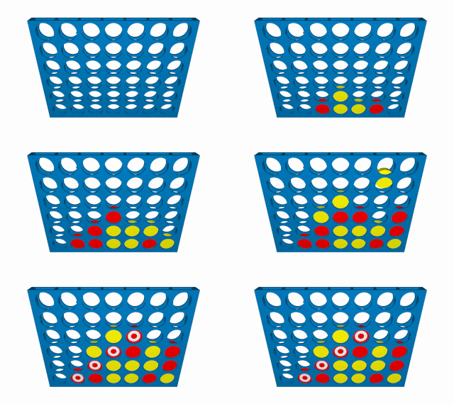
Play Connect Four against an Artificially Intelligent robot with variable difficulty. Prepare to test your ability to think into the future and your proficiency at connecting your pieces against an ideal player. Connect Four
Objectives & Introduction
The objectives of this project is to implement a robotic connect four player with the same capabilities as a human being with respect to the task of connecting pieces by inserting them into one of seven columns at the top of the board. Just as a human can see where his opponent has played his move and can insert his next move into the board, this robot will implement imitations of these basic human abilities.
Team Members & Responsibilities
   Matthew Carlis   (Jack of all Trades) - Hardware/Mechanical,
                                           Artificial Intelligence,
                                           System Architect,
                                           Technical Writer.

   Alexander Koumis (Image/Driver Guru)  - Drivers,
                                           Image Processing,
                                           Software Interfaces.
Status Video: https://www.youtube.com/watch?v=txRglMCjcsI&feature=youtu.be
Schedule
| Story# | Points | Task | Description |
|---|---|---|---|
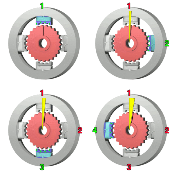
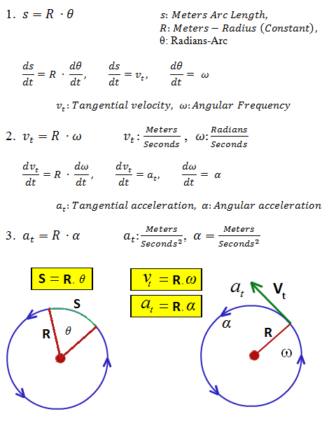
| 1 | 15 | Motor Controller | Write a Stepper motor driver with variable frequency capabilities with constant linear acceleration. This driver should slowly speed up the motor and slowly bring it down while being capable of mapping PWM frequency to pulley frequency. |
| 2 | 10 | Bluetooth Socket. | The micro-controller will be run in combination with a workstation using Bluetooth message passing. The workstation will implement the AI programming where the micro-controller simply tells the workstation through Bluetooth where each move is made by the human and is returned the column number of where to insert the robots next piece. The workstation will implement a Python program interface. |
| 3 | 20 | AI Brain. (It's alive!) | A Python program running on an workstation will implement the "Brain" of the robot where messages are passed between the micro-controller and workstation through Bluetooth. This program will determine where the robot will insert his next move based on which column the human inserts into as reported through the Bluetooth message protocol. |
| 4 | 30 | Mechanical System. | The mechanical system be capable of inserting it's own pieces using linear motion and a stepper motor. The robot will drop his piece into a funnel device which is driven over the column for which the robot wishes to play. After his human opponent has inserted his piece the robots eyes will detect the location of the humans insertion and reply by inserting his next piece. |
| 5 | 25 | The Eyes. | Using the pixy camera to determine the current configuration of the Connect Four board for the robotic player. Using statistical filtering by oversampling the frames the robot will be see each piece as it is inserted. |
| Story# | Points | Story | Burn-down | Time Invested | Actual |
|---|---|---|---|---|---|
| 1 | 15 | Motor Controller | 10 | 15 Hours | 14% |
| 2 | 10 | Bluetooth Socket. | 5 | 3 Hours | 4% |
| 3 | 20 | AI Brain. (It's alive!) | 15 | 18 Hours | 14% |
| 4 | 30 | Mechanical System. | 18 | 30+ Hours | 39% |
| 5 | 25 | The Eyes. | 10 | 40+ Hours | 39% |
| Event# | Date | Task | Actual |
|---|---|---|---|
| 1 | 3/1 | Spec out Design | Completed: Started the system hardware/mechanical specs and materials ordering. Software interfaces are well defined, but not implemented. |
| 2 | 3/18 | Ordered Materials | Completed: Completed mechanical design/research and ordered the majority of the significant materials. (Stepper motor, timing belt/pulleys, liner motion accessories) |
| 3 | 4/1 | Structure Materials | Completed: Received and obtained the majority of the significant materials for the mechanical structure. |
| 4 | 4/20 | Major Milestone | Completed: Bluetooth interface, Stepper Motor Driver, Mechanical specs/ordered, AI implementation. |
| 5 | 4/27 | Projected | ToDo: Finish assembling the mechanical, add linear acceleration to motor driver. |
Parts List & Cost
Give a simple list of the cost of your project broken down by components. Do not write long stories here.
| Qty (Extra) | Description | Manufacturer | Cost |
|---|---|---|---|
| 1 | Stepper Motor Driver 3A | SmartSain | $19.99 |
| 1 | Stepper Motor | Lin Engineering | $45.90 |
| 1 | 24V-40W PSU. | CircuitSpecialists | $14.79 |
| 1 | Pixy Camera CMUcam5 | Pixy | $69.99 |
| 1 | XBee Bluetooth | XBee | $27.95 |
| 2 | Timing Pulley's | N/A | $11.95 (each) |
| 1 | Timing Belt | N/A | $9.95 |
| 4 | Linear Rail Guide | N/A | $3.95 (each) |
| 2 | Linear Bearing w/Platform | N/A | $6.95 (each) |
| 2 | 8mm Linear Motion Rail/Shaft Steel | N/A | $15.25 (each) |
Design & Implementation
System Diagram
The following graphic provides a high-level representation of the system's various software/hardware/human interfaces:
Hardware Design
Discuss your hardware design here. Show detailed schematics, and the interface here.
Hardware Interface
In this section, you can describe how your hardware communicates, such as which BUSes used. You can discuss your driver implementation here, such that the Software Design section is isolated to talk about high level workings rather than inner working of your project.
- Physical Layer Interfaces
- SPI - Pixy Camera
- Bluetooth - Laptop Communication
- PWM (stepper) - 1 Wire PWM with 2 Control Signals.
- PWM (servo) - 2 Wire PWM.
Software Design
The system's software interfaces are comprised of the following components (organized by their respective hardware hosts):
- Laptop
- SJSU One
Bluetooth Socket Interface
Connect 4 AI
GameTask
MotorTask
PixyTask
Drivers for the Pixy were designed using Ozmekian system principles (every machine characteristic/action has a corresponding human analogue). The Pixy's primary tasks as part of Konnector is to send the location and coordinates of human-inserted Connect 4 game chips to the SJSU One board. This involves recording location/coordinate information of incoming blobs, performing statistical analysis on said blobs, and subsequently notifying other system components once a human chip-insertion has been detected. The Pixy's software interface is therefore comprised of the classes PixyBrain, PixyEyes, and PixyMouth, each one encompassing the corresponding facilities that would be required of a human assuming the same role.
Following the same analogy, the 'Pixy' class can be thought of as the system's consciousness/soul, defining actions for each component to take in response to system states. 'PixyTask' then assumes the role of the system's physical body, comprised of all of its individual components, animated by actions invoked by the consciousness during run-time.
The system's states are enumerated as follows: (Github):
enum State_t
{
    CALIB             = 16,
    WAITING_FOR_HUMAN = 17,
    WAITING_FOR_BOT   = 18,
    ERROR             = 19,
    RESET             = 0x01, // SW(1)
    EMA_ALPHA_UP      = 0x02, // SW(2)
    EMA_ALPHA_DOWN    = 0x04, // SW(3)
    SW_4              = 0x08  // SW(4)
} eState, eLastState;
The CALIB state is run at system startup, constructing a 6x7 grid of chip positions to be referenced later in the game (full discussion).
The WAITING_FOR_HUMAN and WAITING_FOR_BOT states encompass the system's behavior when waiting for human chip-insertion, and the AI's next-move instruction, respectively.
RESET, EMA_ALPHA_UP/DOWN and SW_4 are mapped to the SJSU One's push-buttons , respectively, with RESET wiping current calibration settings/game state, and EMA_ALPHA_UP/DOWN allowing run-time adjustment of the tolerance parameter used in the chip-detection algorithm.
Unexpected data values/return codes cause the system to enter the ERROR state, where accumulated error messages are retreived from an error queue.
PixyTask invokes state reactions by calling vAction() within the bool run(void*) function (a task-runner interface):
bool run(void *p)
{
    pPixy->vAction();
    return true;
}
void vAction() is then defined as:
void vAction()
{
    eLastState = eState;
    xFuncMap->vResponse(eState)();
}
xFuncMap is prepopulated with lambda functions in response to every possible State_t key. For example, handlers for WAITING_FOR_HUMAN and WAITING_FOR_BOT are set as follows:
xFuncMap->vSetHandler(WAITING_FOR_HUMAN, [&] ()
{
    // Blocks until N chips are sampled
    pPixyBrain->lSampleChips(pPixyEyes.get());
    eState = WAITING_FOR_BOT;
});

xFuncMap->vSetHandler(WAITING_FOR_BOT, [&] ()
{
    PixyCmd_t xBotInsertCmd;
    // Blocks until command received over shared queue
    if (xQueueReceive(getSharedObject(shared_PixyQueue), &xBotInsertCmd))
    {
        PixyBrain->lBotInsert(xBotInsertCmd);
        eState = WAITING_FOR_HUMAN;
    }
});
These reactive symantics are made possible by the templated 'FuncMap_t' utility struct, allowing function pointers (std::function) to be stored in a map, invoked later in response to key values of arbitrary type:
template<typename KEY_T, typename FUN_T, typename ... ARG_T>
struct FuncMap_t
{
    /* The core std::map object, mapping KEY_T's to std::function's */
    map<KEY_T, function<FUN_T(ARG_T ... xArgs)>> fpMap;

    /* Method used to insert (KEY_T, std::function) key/value pairs */
    void vSetHandler(KEY_T xElem, function<FUN_T(ARG_T ... xArgs)> fnHandler)
    {
        fpMap[xElem] = fnHandler;
    }

    /* Method called during run-time to invoke stored lambda function */
    function<FUN_T(ARG_T ... xArgs)>& vResponse(KEY_T xElem)
    {
        return fpMap[xElem];
    }
};
PixyBrain
Effort is taken to compartmentalize computational duties solely to PixyBrain. #PixyEyes performs no role other than to record seen blocks over a certain time period, providing this information to PixyBrain when queried. PixyBrain uses this information, along with prior knowledge of current game state, to determine when the human opponent has inserted a new chip. PixyBrain then delegates PixyMouth to forward this information to the Python AI, sending the (int) column value over a shared FreeRTOS queue.
Corner calibration
The first action executed by the system is to determine pixel coordinates (x, y) of each of the board's four corner chip slots. A predefined number of blocks are sampled from the stream sent from #PixyEyes , each one adding to one of four running averages depending on the quadrant they fall in. Assuming only the top left, top right, bottom left, and bottom right slots are occupied by the set calibration chip color, the final average coordinates are used to construct the full grid of slot locations.
PixyEyes
PixyEyes handles parsing raw Pixy input to the SJSU One. Example code [was provided] for this purpose but, unfortunately, did not function correctly under FreeRTOS' tight memory constraints. Alternative drivers were written, attempting to conform to the [defined protocol], where data is sent in 14-byte blocks as follows:
Bytes    16-bit word    Description
----------------------------------------------------------------
0, 1     y              sync: 0xaa55=normal object, 0xaa56=color code object
2, 3     y              checksum (sum of all 16-bit words 2-6)
4, 5     y              signature number
6, 7     y              x center of object
8, 9     y              y center of object
10, 11   y              width of object
12, 13   y              height of object
PixyMouth
Implementation
This section includes implementation, but again, not the details, just the high level. For example, you can list the steps it takes to communicate over a sensor, or the steps needed to write a page of memory onto SPI Flash. You can include sub-sections for each of your component implementation.
Testing & Technical Challenges
Describe the challenges of your project. What advise would you give yourself or someone else if your project can be started from scratch again? Make a smooth transition to testing section and described what it took to test your project.
Include sub-sections that list out a problem and solution, such as:
My Issue #1
Discuss the issue and resolution.
Conclusion
Conclude your project here. You can recap your testing and problems. You should address the "so what" part here to indicate what you ultimately learnt from this project. How has this project increased your knowledge?
Project Video
Upload a video of your project and post the link here.
Project Source Code
- Sourceforge Source Code Link (Project Baseline)
- Connect Four:
References
Acknowledgement
Any acknowledgement that you may wish to provide can be included here.
References Used
List any references used in project.
Appendix
You can list the references you used.


