Difference between revisions of "S15: Cyclops: Smart RC Car"
(→Hardware Interface) |
(→Hardware Design) |
||
| Line 216: | Line 216: | ||
Discuss your hardware design here. Show detailed schematics, and the interface here. | Discuss your hardware design here. Show detailed schematics, and the interface here. | ||
| + | *Overall design | ||
| + | [[File:Example.jpg]] | ||
* GPS | * GPS | ||
Revision as of 19:50, 24 May 2015
Contents
Grading Criteria
- How well is Software & Hardware Design described?
- How well can this report be used to reproduce this project?
- Code Quality
- Overall Report Quality:
- Software Block Diagrams
- Hardware Block Diagrams
- Schematic Quality
- Quality of technical challenges and solutions adopted.
Cyclops: Smart RC Car
Abstract
The Smart RC car is an autonomous car that given a destination coordinate, drives to that location without any user interaction. It also has the ability to avoid obstacles in its path with the help of Sonar sensors.
Objectives & Introduction
In a world of autonomous systems, it is only a matter of time until we see all cars on the roads that drive themselves. Our concept for the RC car is based on that idea that cars will be able to drive themselves. The car will drive itself from a starting point to an ending point provided by the driver, which in our case is the host computer. The car will also have the capability to avoid obstacles in its path using three LV-MaxSonar-EZ0 Ultrasonic Range Sensors in the front. A GPSBee module with a SIM28 GPS receiver is being used to track the position of the car. This allows the car to navigate to the provided location autonomously. In addition to GPS navigation, a pixyCam will be used for lane detection to assist in the automated driving. So, jointly, the car will be able to drive following lanes, just like a real car on the road, and will have sensors to be able to avoid obstacles, along with reaching a destination with the help of GPS.
Team Members & Responsibilities
- Hector Prado-Guerrero
- GPS / Navigation Development
- Calvin Lai
- Sonar Sensors / Lane Guidance
- Britto Thomas
- Motor Control / Wireless Communication
Schedule
| Week# | Date | Task | Status | Actual |
|---|---|---|---|---|
| 1 | 04/17 | PWM tasks Completed
Mounting equipment Completed Some code for object tracking Some code on GPS |
PWM Complete
Mounting Complete Object is being tracked but we need to train it to follow a specific color of tape. Code for GPS is still being worked. |
4/19 4/19 4/21 4/21 |
| 2 | 04/24 | GPS and Compass completed
Wireless completed Sensors completed |
Compass - completed
Wireless - completed Sensors - completed GPS - completed |
4/27
4/27 4/27 5/24 |
| 3 | 05/01 | Obstacle avoidance Completed
GPS Navigation completed |
Obstacle avoidance - mostly complete |
GPS Navigation - In Progress |
| 4 | 05/08 | Object Tracking / Lane Guidance Completed | Pending | |
| 5 | 05/15 | Testing and Verification | Pending | |
| 6 | 05/22 | More Testing and Verification
Possibly Android app over BT |
Pending | |
| 7 | 05/25 | Demo Date | Pending |
Parts List & Cost
| Line Item# | Part Description | Vendor | Part Number | Qty | Cost ($) |
|---|---|---|---|---|---|
| 1 | Lightning EPX Pro 1/10 4WD scale RC car | Redcat Racing | 1 | 200.00 | |
| 2 | SJSU One Board | Preet Industries | 3 | 240.00 | |
| 3 | GPS Bee kit (with Mini Embedded Antenna) | Seeed Studio | SEN133D1P | 1 | 39.95 |
| 4 | Smart Vision Sensor - Object Tracking Camera | Pixy | CMUcam5 | 1 | 69.00 |
| 5 | Triple Axis Compass Magnetometer Sensor Module | 365buying | HMC5883L | 1 | 8.99 |
| 6 | 2.4GHz, 3 dBi at 5Ghz Rubber Duck WiFi Antenna | Embedded Works | EW2458-02 | 2 | 8.00 |
| 7 | Jumper Wires | Pack of 100 | 10.00 | ||
| 8 | XBEE Explorer USB | SparkFun | 5030 | 1 | 24.95 |
| Additional Shipping | $0.00 | ||||
| Total Cost | $600.89 |
.
Design & Implementation
The design section can go over your hardware and software design. Organize this section using sub-sections that go over your design and implementation.
Hardware Design
Discuss your hardware design here. Show detailed schematics, and the interface here.
- Overall design
- GPS
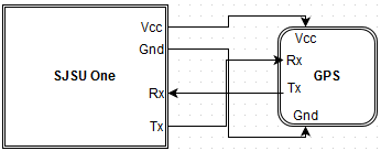
- Figure GPS_WIRING
- As seen in figure GPS_WIRING, one can see the needed wires to connect to the GPS module in order to communicate with it via UART.
Hardware Interface
In this section, you can describe how your hardware communicates, such as which BUSes used. You can discuss your driver implementation here, such that the Software Design section is isolated to talk about high level workings rather than inner working of your project.
- GPS
- For GPS, the only interface that was used, and basically the easiest one, was UART. Refer to Hardware design Figure GPS_WIRING to see the specifics on what exactly was wired.
Software Design
Show your software design. For example, if you are designing an MP3 Player, show the tasks that you are using, and what they are doing at a high level. Do not show the details of the code. For example, do not show exact code, but you may show psuedocode and fragments of code. Keep in mind that you are showing DESIGN of your software, not the inner workings of it.
Implementation
This section includes implementation, but again, not the details, just the high level. For example, you can list the steps it takes to communicate over a sensor, or the steps needed to write a page of memory onto SPI Flash. You can include sub-sections for each of your component implementation.
GPS
For GPS, communication can be done over a few methods: I2C, UART, SPI, etc. For this project, UART will be used to collect data from the GPS module. Here are a few steps that should be done when interfacing with GPS module.
- 1. Plug into XBee socket.
- a. If not using XBee socket type GPS module, then make sure to plug in the GPS VCC an appropriate power source. Make sure ground from GPS is tied in with ground from SJSU one board.
- Then, make sure to wire the Tx pin of the GPS to the Rx pin of the SJSUOne board. If you would like to configure the GPS to, for example, only output a certain type of sentence, then wire GPS Rx to SJSUOne Tx pin.
- 2. If you see that you aren't getting any data using a basic program to getChar from uart, then refer to Issue #2.
Magnetometer
The magnetometer is used to find the current heading of the car. Without this heading, it would be impossible to face the vehicle in the correct direction without first driving in an arbitrary direction to orient according to GPS location.
The magnetometer is an HMC5883L which is a Triple Axis Compass Magnetometer Sensor Module. The module uses I2C for communication and outputs data in an XYZ, pitch, yaw, roll format. In order to use this data, it first needed to be converted to a heading in degrees.
Testing & Technical Challenges
Describe the challenges of your project. What advise would you give yourself or someone else if your project can be started from scratch again? Make a smooth transition to testing section and described what it took to test your project.
Include sub-sections that list out a problem and solution, such as:
Issue #1
Motor controls were not working as per the documentation of previous groups.
- It is important that there is a COMMON GROUND for the motor and the servo. So we connected all the required grounds to the SJSU boards ground and it all functioned as needed.
Issue #2
2) GPS XBee module from Seeedstudio v1.4
- Connecting the GPS directly into the XBee socket of the SJSU One board would not work. Reason being was that the breakout board for the GPS module created a Tx pin that was too weak to drive the Rx pin on the SJSU one board.
- Solution: Solder a jumper wire directly to the Tx pin of the GPS chip on the breakout board, and connect that to the external Rx pin of the SJSU one board. The Rx pin of the GPS module works fine for sending commands to configure the GPS.
Issue #3
2) GPS XBee module from Seeedstudio v1.4
- Trying to capture the NMEA sentences and properly parse it. The GPS outputs data constantly, and you must be able to capture that properly. Make sure to properly setup your variables in order to capture the data.
- Solution: Captured only the exact amount of characters coming in from the GPS. Created a char array, with a certain number of elements, and used that to capture the data, the catch is, however, that you've gotta clear the array prior to capturing the data. Essentially, each time you're trying to capture the data, make sure to clear out the char array, or char* so that it doesn't somehow get messed up like it did for us.
- For parsing through the NMEA sentence after it's been captured, the same concept must apply, you should create an array with only the number of elements you want, and make sure to clear before trying to parse. We had issues trying to set the data directly, like array[i] = nmeaSentence[i], it started overwriting stuff somehow.
- Just use a pointer and dereference it to store it.
Conclusion
Conclude your project here. You can recap your testing and problems. You should address the "so what" part here to indicate what you ultimately learnt from this project. How has this project increased your knowledge?
Project Video
Upload a video of your project and post the link here.
Project Source Code
References
Acknowledgement
Any acknowledgement that you may wish to provide can be included here.
References Used
List any references used in project.
Appendix
You can list the references you used.

