Difference between revisions of "S15: CAN controlled RGB LED cubes"
Proj user12 (talk | contribs) (→Software Design) |
Proj user12 (talk | contribs) (→Software Design) |
||
| Line 228: | Line 228: | ||
'''Tools used to Develop Android Application:''' | '''Tools used to Develop Android Application:''' | ||
| − | + | * Android Studio based on IntelliJ IDEA. | |
· Java Development kit 7 by Oracle. | · Java Development kit 7 by Oracle. | ||
Revision as of 22:36, 28 April 2015
Contents
Grading Criteria
- How well is Software & Hardware Design described?
- How well can this report be used to reproduce this project?
- Code Quality
- Overall Report Quality:
- Software Block Diagrams
- Hardware Block Diagrams
- Schematic Quality
- Quality of technical challenges and solutions adopted.
Project Title
Abstract
In this project, data(1 byte) sent from an android application will be displayed in a 3D form on a LED cube. Two LED cubes will be connected to two different SJone boards, these SJone boards are connected to a third SJone board using CAN bus. The LED cubes will be connected to their respective SJ boards through shift registers. The boards will implement SSP protocol to communicate with the shift registers. A bluetooth module is connected to third SJone board. Android application sends data to be displayed along with the information about the SJone board(one of the LED cube) to be selected.
Objectives & Introduction
Show list of your objectives. This section includes the high level details of your project. You can write about the various sensors or peripherals you used to get your project completed.
Team Members & Responsibilities
- Chitrang Talaviya
- LED cube design
- Implementing CAN protocol
- Bluetooth module interfacing
- Navjot Singh
- Implementing CAN protocol
- Bluetooth module interfacing
- FreeRTOS environment
- Anuj Korat
- LED cube design
- Generating dynamic patterns
- Implementing SSP with the shift registers
- Daamanmeet Paul
- Android application development
- Generating different characters on LED cube
Schedule
Show a simple table or figures that show your scheduled as planned before you started working on the project. Then in another table column, write down the actual schedule so that readers can see the planned vs. actual goals. The point of the schedule is for readers to assess how to pace themselves if they are doing a similar project.
| Week# | Start Date | Task | Status | Completion Date |
|---|---|---|---|---|
| 1 | 3/15 | Finalizing & ordering components
-Going through the requirements of the project -Order hardware components based on the final list |
Completed | 3/17 |
| 2 | 3/27 | 3x3x2 LED cube testing with SPI interfacing
-Studying the SC74HC595 shift register datasheet -Constructing a 3x3x2 LED cube for testing purpose -Interfacing of shift register using SSP1 with LPC1758 -Cascading of 4 shift registers using SSP1 to control anodes & RGB cathodes |
Completed | 4/10 |
| 3 | 4/8 | Bluetooth Interface with SJone board through Android APK
-Testing the AT commands of Bluetooth RKI-1545 module using hyperterminal(Completed) -Testing interfacing of bluetooth using UART2(In progress) |
In progress | 4/17 |
| 4 | 4/8 | Android application | In progress | 4/25 |
| 5 | 4/16 | 4x4x4 LED cube construction
-Building 2 LED cubes -Interfacing & cascading of the shift registers with SJone boards to control 16 anodes and 12 cathodes using SIPO configuration of shift register -Interfacing of LED cubes with shift registers |
In progress | 4/26 |
| 6 | 4/20 | CAN protocol programming
-Studying the CAN protocol datasheet(completed) -Setting up the interface of CAN transceiver and SJone boards(In progress) -Initially making two-nodes CAN configuration(Not started) |
In progress | 4/30 |
| 7 | 4/27 | Generating patterns on LED cubes
-Building libraries for generating Alphabets & numbers on the LED cubes |
Not Started | 5/7 |
| 8 | 5/1 | Implementing FreeRTOS for the system
-Implementing queue RTOS feature to connect the bluetooth interface and the CAN interface of the LPC1758 board |
Not Started | 5/10 |
| 9 | 5/10 | Final Debugging & testing | Not Started | 5/15 |
Parts List & Cost
| # | Components | Quantity | Price($)/component |
|---|---|---|---|
| 1 | RGB LEDs pack of 100 | 2 | 9.95 |
| 2 | CAN transceivers | 15 | Free |
| 3 | Shift registers, SC74HC595 | 10 | 1.49 |
| 4 | SJone boards | 3 | 80 |
| 5 | Bluetooth module | 1 | 20 |
| 6 | Steel wire | 1 | 8 |
| 7 | Soldering kit | 1 | ~40 |
| 8 | Jumper wires(each type) | 1 | 25 |
| 9 | ULN 2003 | 4 | 12 |
Design & Implementation
The design section can go over your hardware and software design. Organize this section using sub-sections that go over your design and implementation.
Hardware Design
Discuss your hardware design here. Show detailed schematics, and the interface here.
Hardware Interface
In this section, you can describe how your hardware communicates, such as which BUSes used. You can discuss your driver implementation here, such that the Software Design section is isolated to talk about high level workings rather than inner working of your project.
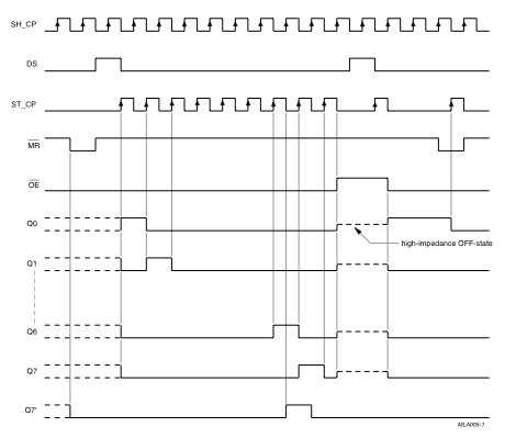
Shift registers have been used to communicate betwen the SJone board and the LED cubes. As the dimension of the cue is 4 x 4 x 4, it needs a total of 28 pins to control
it, 16 pins to control 16 groups of 4 LED anodes and 12 pins to control 4 planes of the RGB lines. As we do not have that many pins on SJone board, we will be using 4 Serial-
input-parallel-output shift registers to drive the LED terminals. This eases our job as only 4 pins are used from the board to drive 28 LED terminals.
The communication bus used between the LPC1758 board and the shift registers is SSP-Synchronous Serial Port. The driver written for the communication is as shown in Fig. All the shift registers are cascaded, meaning the serial output of one, connected to the serial input of the other. This way a total of 32 bits of serial data from the board can be converted into parallel outouts which are given to its respective LED terminals.
Software Design
Show your software design. For example, if you are designing an MP3 Player, show the tasks that you are using, and what they are doing at a high level. Do not show the details of the code. For example, do not show exact code, but you may show psuedocode and fragments of code. Keep in mind that you are showing DESIGN of your software, not the inner workings of it.
Android Application Development:-
Tools used to Develop Android Application:
- Android Studio based on IntelliJ IDEA.
· Java Development kit 7 by Oracle.
· Android ADB interface.
· Android API 21 platform.
Application Features:
· Bluetooth pairing up to 6 devices at a time.
· Facility to change Transmission Protocol within the Application.
· Send Data serially to any serial Bluetooth Device.
· Receive Data serially from any Bluetooth device using same protocol.
Application development Procedure:-
Application is developed upon the sample code provided by http://developer.android.com/guide/topics/connectivity/bluetooth.html
Bluetooth APIs setup available in the android bluetooth package:
· BluetoothAdapter
Used for the local Bluetooth adapter (Bluetooth radio). The BluetoothAdapter is the entry-point for all Bluetooth interaction. It is used to discover other Bluetooth devices, query a list of bonded (paired) devices, instantiate a BluetoothDevice using a known MAC address, and create a BluetoothServerSocket to listen for communications from other devices.
Implementation
This section includes implementation, but again, not the details, just the high level. For example, you can list the steps it takes to communicate over a sensor, or the steps needed to write a page of memory onto SPI Flash. You can include sub-sections for each of your component implementation.
Testing & Technical Challenges
Describe the challenges of your project. What advise would you give yourself or someone else if your project can be started from scratch again? Make a smooth transition to testing section and described what it took to test your project.
Include sub-sections that list out a problem and solution, such as:
My Issue #1
Discuss the issue and resolution.
Conclusion
Conclude your project here. You can recap your testing and problems. You should address the "so what" part here to indicate what you ultimately learnt from this project. How has this project increased your knowledge?
Project Video
Upload a video of your project and post the link here.
Project Source Code
References
Acknowledgement
Any acknowledgement that you may wish to provide can be included here.
References Used
List any references used in project.
Appendix
You can list the references you used.

