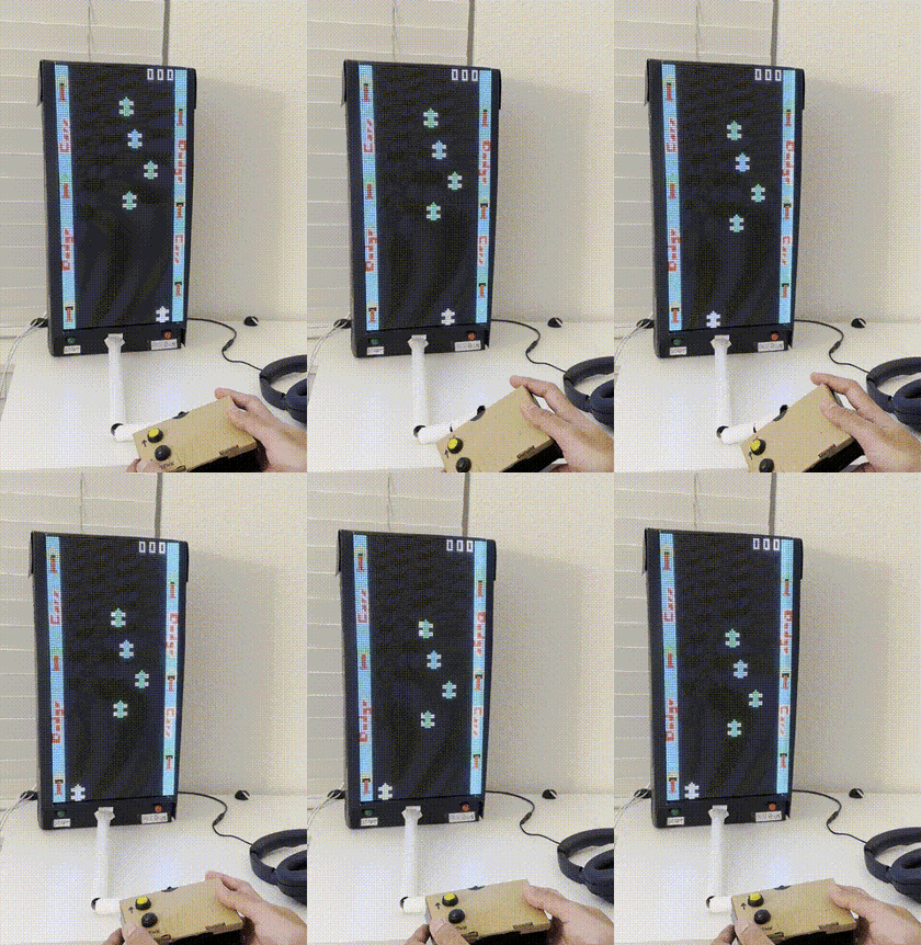
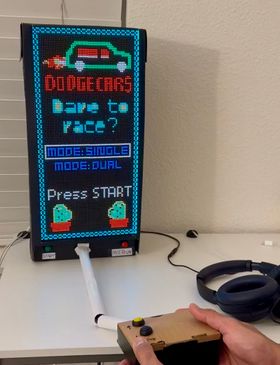
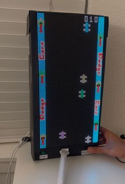
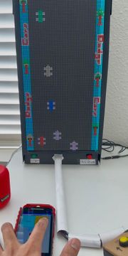
F24: Dodge Cars
Contents
[hide]Hardware and gameplay snapshots
Abstract
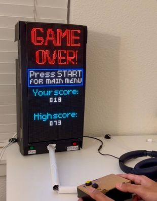
Dodge Cars is a fast-paced action game where players control a vehicle to avoid collisions with incoming obstacles. The objective is to maneuver the car left or right, dodging other cars or objects as they approach. As the game progresses, the speed of obstacles increases, adding difficulty. The game utilizes a 64x64 LED matrix display for visuals, with an SJ2 board for processing. A button allows players to access the menu, navigate, and pause the game (or optional photosensor). An ultrasonic sensor detects if the player is sitting too close to the screen, warning them to adjust their position. An accelerometer is used to control the left and right movements of the player car. The final score of the player will be displayed at the end of every game and a speaker attached to the board will generate the game sounds.
Introduction
Dodge Cars is an engaging and fast-paced action game designed to test players' reflexes and coordination. Players navigate a car through a dynamically changing environment, dodging incoming obstacles that become increasingly difficult to avoid as the game progresses. This interactive experience leverages modern hardware and creative gameplay mechanics, delivering a fun and challenging game suitable for players of all ages.
The game is powered by a 64x64 LED matrix display that provides a vibrant, retro-inspired visual experience. An SJ2 board acts as the central processing unit, seamlessly handling the game's inputs, outputs, and real-time logic. Players control the movement of their car using an accelerometer, adding an immersive, physical dimension to the gameplay. Safety and accessibility are also prioritized, with features like an ultrasonic sensor to promote proper player posture and a button or optional photosensor for intuitive menu navigation. To enhance the overall experience, a speaker generates immersive game sounds, and the final score is displayed at the end of each session, encouraging replayability.
Objective
The primary objective of this project is to develop an interactive game system that combines hardware and software components to deliver a compelling gaming experience. Key objectives include:
- Design an engaging game loop where players must dodge obstacles using precise control of a car, with increasing difficulty as the game progresses.
- Utilize modern hardware components like a 64x64 LED matrix for visuals, an accelerometer for motion control, and an ultrasonic sensor to enhance player safety.
- Provide intuitive user interactions through menu navigation using a button or photosensor, along with clear audio-visual feedback from the speaker and display.
- Promote player engagement and challenge by showcasing the final score at the end of each game and encouraging improvement through replayability.
- Integrate safety measures by alerting players if they are sitting too close to the screen, fostering healthier gaming habits.
This project aims to blend creativity, engineering, and user-centric design into a fun and immersive gaming system that highlights the potential of embedded systems in interactive applications.
Team Members & Responsibilities
- Shreyas
- Worked on Accelerometer Sensor
- Teja
- Worked on MP3 decoder
- Navaneeth
- Worked on the Game logic and LED screen
Schedule
| Week# | Start Date | End Date | Task | Status |
|---|---|---|---|---|
| 1 |
|
|
|
|
| 2 |
|
|
|
|
| 3 |
|
|
|
|
| 4 |
|
|
|
|
| 5 |
|
|
|
|
| 6 |
|
|
|
|
| 7 |
|
|
|
|
| 8 |
|
|
|
|
| 9 |
|
|
|
|
| 10 |
|
|
|
|
Parts List and Cost
| Part | Model | Quantity | Cost |
|---|---|---|---|
|
|
|
|
|
|
| |
|
|
| |
|
|
| |
|
|
|
Design & Implementation
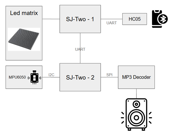
The overall implementation incuded two SJTwo boards, a bluetooth module, gpio switches and a bluetooth application. The details of the same are discussed below.
Hardware Design
Hardware Interface
The relevant hardware modules are the following.
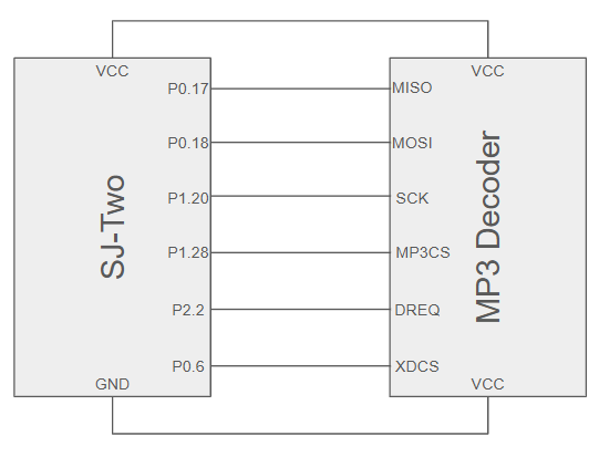
- 1. Created a SPI (SSP0) driver to communicate with MP3 decoder and SD Card. We used the following pins:
| MP3 Decoder Pin | Pin Description | Corresponding SJ2 Pin |
|---|---|---|
| MISO | SSP0 MISO (Master In Slave Out) | P0_17 |
| MOSI | SSP0 MOSI (Master Out Slave In) | P1_18 |
| SCK | SSP0 SCK (Clock Pin) | P1_20 |
| SSEL | SSP0 SSEL (Slave Select) | P1_28 |
| MP3CS (Chip Select) | GPIO | P0_6 |
| DREQ | GPIO | P2_2 |
| VCC | VCC(3.3V) | On Board |
| GND | GND | On Board |
Software Design
We defined a structure to organize the GPIO pins needed for communication with the LED matrix, including those for clock, latch, and RGB control for each row. The code initializes these pins as output and manages the timing signals required to transfer data to the matrix. It also controls which row of LEDs is being addressed by activating the corresponding row pins. The driver handles the display of pixels by storing pixel data in a 2D array, which is periodically updated and sent to the matrix. The display is refreshed by shifting the pixel data and applying the appropriate RGB values to each LED. The overall system manages the multiplexing of the display, updating each row in sequence, and refreshing the entire display with a controlled delay to adjust brightness.
- LED Matrix:
- 1. Initialized LED matrix connected pins to board IOs.
- 2. Designed matrix driver for screen display by reading an matrix.
- 3. Designed pause menu, main menu and gameplay environment for different states of game.
- 4. Used GPIO pins as buttons as controls in main menu
- Graphics design:
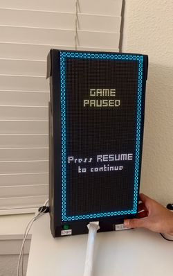
The graphics for the main menu, pause menu, boundary walls during the game, and gameover screen was created on a pixel art application. 128x64 pixel size was chosen and the required text and animations were manually painted. The cars for the gameplay were drawn using the draw_pixel command implemented in code and the car wheels were drawn separately in a different color.
- 1. Created 128x64 BMP images using pixel art
- 2. Created function to display the BMP images to LED matrix
- 3. Created function to draw player and traffic cars with defined initial positions
- 4. Developed a logic to move the traffic down towards player, with varying pace as score increases
The SJTwo board used for driving the LED matrix would receive instruction via uart to control the cursor for game mode selection. The logic for the same is shown below:
while true:
     if button_up_pressed:
       send 'U' over UART // Up
   if button_down_pressed:
       send 'D' over UART // Down
   delay()
- On-board Accelerometer:
- 1. Initialized I2C channels for taking the x, y and z reading from the sensor and input the readings into the LED matrix gameplay.
- 2. Used accelerometer readings as inputs for moving the car left and right during gameplay. Uses two tasks:
1. read_data Task
- Initializes I2C communication with the accelerometer
- Continuously reads X and Y axis data from the accelerometer
- Interprets the data to detect tilt (left, right, or no tilt)
- Updates a global variable (tilt_data_to_send) with the tilt direction
2. board_1_sender_task
- Periodically sends the tilt data over UART to the second board attached to the LED matrix display
- This task enables communication of tilt information to the LED matrix
- Integrated sensor with bluetooth sensor to serve as a single player control during dual player co-op.
while true:
   read accelerometer data
   if tilt_left:
       send 'L' over UART
   else if tilt_right:
       send 'R' over UART
   else:
       send 'M' over UART
   delay(small_amount)
- Bluetooth Sensor:
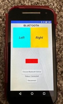
The game was designed to also support multi-player option using the 'Dual' mode in the main menu section. When this mode is selected two player cars are displayed. While one player car is controlled using the accelerometer the other is controlled via bluetooth, using a specially designed smartphone app.
- 1. Used Bluetooth sensor to communicate with LED matrix display to move car left and right.
- 2. Worked as a single player control during dual player co-op.
- 3. Used as a point of reference for game restart on the game over screen(START button can also be used). This sensor uses just one task for it's computation:
 while true:
   if bluetooth_data_received:
       if data == '1':
           move_player_two_car_left()
       else if data == '2':
           move_player_two_car_right()
       else if data == '3' and game_is_over:
           restart_game()
   delay(small_amount)
- MP3 Player:
- 1. Initialize using SPI.
- 2. Check state of game and select appropriate task.
- 3. Load song from SD card into MP3 decoder.
There are two tasks, one that updates the state of the game to read data from the SD card present on the SJ2 board while the other uses a queue to receive data from the first task and relay it to the MP3 decoder.
Task 1: Mp3 Reader

const char* current_song = NULL;
while True:
    Check state of game and switch to case STATE:
        Updates current songname
        load_song_into_queue(songname):
             if freaddir(root_directory) == True:
                Check for songname in directory
                Read song data from mp3 file into queue
                Close file && Close directory
                return;

Task 2: MP3 player task

spi_cs() // Initialize SPI communication
Initialize the DREQ pin.
Enter an infinite loop:

    xQueueReceive(song_data)
    Iterate over each byte in the chunk:
        Check DREQ pin to see if the decoder is ready to receive data
        exchange_data(byte)
spi_ds()- 2. Set device with selected sd card and volume.
Implementation
The 64x64 LED matrix we used were from Waveshare and had a pitch of 3mm. It features 64 rows and 64 columns of LEDs, with each LED capable of emitting RGB colors. The matrix is typically interfaced through a series of GPIO pins that control the rows and columns, which are used to manage the pixels. The main interfacing include GPIO pins that control the RGB colors for each row, along wi h additional pins for clock, latch, and output. These connections allow for dynamic addressing of individual LEDs, which can be controlled to display images, text, or animations. The matrix usually operates using a multiplexing technique where each row is updated in sequence, creating the appearance of a continuous display. Proper timing and control of these pins are essential for achieving smooth, flicker-free visual output.
For the graphics of the game, the cars are drawn using the draw_car function as shown below. In addition, the boundary walls for the game are displayed using an image display function. The images are first drawn in a pixel art application, converted to BMP files and in turn are converted to header files using the xxd -i command in terminal. The header file is stored in flash using the const command so that RAM does not get used up unnecessarily.
Convert BMP image to TrueColor type for proper display: magick start_screen.png -type TrueColor start_screen.bmp Convert BMP file to header file: xxd -i start_screen.bmp > start_screen.h
static void draw_car(car_t car) {
 for (size_t row = 0; row < car_width; row++) {
   for (size_t col = 0; col < car_height; col++) {
     draw_pixel(car.car_row_start + row, car.car_col_start + col, car.car_color);
   }
 }
 draw_pixel(car.car_row_start + (car_width / 2), car.car_col_start - 1, car.car_color);
 draw_wheels(car);
}
The main states of the game are detected using flags for the appropriate state. As game state changes, the values are updated for the flag, and a running task ensures that the data gets sent to other controller. To control the player car motion we used a second SJTwo controller with an onboard accelerometer which is controlled via I2C. This board communicates the left or right tilt it experiences, to the master board which drives the LED matrix, via UART. When this controller is tilted left, the player car moves left and when tilted right, it moves right. This controller also housed the SD card that was used to read and send songs to the MP3 decoder to play, via SPI interface.
void acc_sensor_task(void *params) {
   while (true) {
       float x_tilt = read_accelerometer_x_axis();
       if (x_tilt < TILT_THRESHOLD_LEFT) {
           uart__polled_put(MASTER_UART, 'L');  // Send left command
       } else if (x_tilt > TILT_THRESHOLD_RIGHT) {
           uart__polled_put(MASTER_UART, 'R');  // Send right command
       }
       vTaskDelay(50);  // Small delay to avoid flooding the UART
   }
}
 static void acc_sensor__receive_task(void *params) {
   char received_byte;
   while (true) {
       if (uart__polled_get(ACC_SENSOR_UART, &received_byte)) {
           if (received_byte == 'L') {
               move_car_left();
           } else if (received_byte == 'R') {
               move_car_right();
           }
           // ... other commands ...
       }
       vTaskDelay(80);
   }
 }
The song to be played for each instance of the game was queued to the decoder via the FreeRTOS queues. When ever a change of game state was identified, the current playing song was cleared from the queue and the new song was sent. The present state of the game is communicated to this board from the master board using the same UART interface. When the multi-player option is enabled, the bluetooth module receives car movement commands from the smartphone app and sends the same to the master board via UART.
 void master_send_gameplay_to_mp3(void *p) {
   while (true) {
       uart__polled_put(ACC_SENSOR_UART, gameplay_mode);
       vTaskDelay(500);
   }
 }
 void audio_task(void *params) {
   QueueHandle_t song_queue = xQueueCreate(5, sizeof(song_t));
   char game_state;

   while (true) {
       if (uart__get(MASTER_UART, &game_state, portMAX_DELAY)) {
           song_t new_song;
           switch (game_state) {
               case 'M':  // Menu
                   new_song = MENU_SONG;
                   break;
               case 'G':  // Gameplay
                   new_song = GAMEPLAY_SONG;
                   break;
               case 'P':  // Pause/Game Over
                   new_song = GAMEOVER_SONG;
                   break;
           }

           xQueueReset(song_queue);  // Clear current song
           xQueueSend(song_queue, &new_song, portMAX_DELAY);
       }

       // Play song from queue using SPI to communicate with MP3 decoder
       // ...
   }
 }
Testing & Technical Challenges
1. We initially faced issues with the extracting the readings from the accelerometer. It took us some time to understand the I2C communication between the SJ2 board and the sensor. When we tried printing the gyroscope and accelerometer values using MPU6050, we started getting just zero values. So we had to make sure we are using the right registers for power management, MPU6050, gyroscope configuration register and the starting register for gyroscope data.
2. We started having issues with the MP3 decoder as well. Though the SD card was being detected by the MP3 decoder, the XDCS pin on the MP3 decoder was not sending audio data to the VS1053B chip to be decoded. We managed to fix this issue by attaching the MP3CS pin to the SSEL pin on the board and using a separate GPIO pin to control the XDCS pin.
3. We faced issues with the LED matrix board. The perfectly working board started flickering all of a sudden. This was because there was an unwanted print statement in the code which was causing this issue.
Conclusion
We used I2C, SPI, UART and other FreeRTOS libraries in our project. After doing the lab assignments and learning the theory in class, we were able to apply that knowledge to implement it in our project especially configuring an external sensor (MPU6050) and an MP3 decoder. Using these protocols, we learnt multiple ways of communicating between the board and other devices. The lab assignments helped us learn how to read an external device's datasheet and use it to debug and verify our programs. This project was a fun learning experience. This project and subject was a tough introduction to embedded systems, but it was also a fun learning experience that has given us much more confidence in being able to familiarize ourselves with unfamiliar APIs and protocols and turn it into a practical application.
Project Video
Detailed video of the game can be found here: https://drive.google.com/drive/folders/1T9-T87jQhvPSepufDYjyNNtZywkLQg5e?usp=share_link
Project Source Code
References
Acknowledgement
I would like to express my heartfelt gratitude to Prof. Preetpal Kang for his invaluable guidance throughout this project. The insightful lectures, hands-on lab sessions, and detailed explanations provided a strong foundation and were instrumental in the successful completion of our work. His dedication to teaching and willingness to clarify concepts made a significant impact on our learning experience.
